Dr. Valery Rudnev on . . .
Induction Hardening Tips: Equipment Selection for Scan Hardening, Part 3
This is the third installment of a multi-part column on equipment selection for induction heat treatment. Part 1, Dr. Valery Rudnev On . . . Induction Hardening Tips: Equipment Selection for Scan Hardening, covered types of scanners, scan hardening system setup, quenching challenges, maximizing process flexibility, and computer modeling. In Part 2, Dr. Valery Rudnev discussed another critical aspect of induction scan hardening: inductor design subtleties and a comparison of different fabrication techniques (brazing vs. CNC
machining vs. 3D printing).
In this installation, Dr. Rudnev focuses on Moveable Inductor versus Moveable Part.
Moveable Inductor versus Moveable Part
As stated in one of the previous installments of this column, when a scan processing mode is chosen, either the inductor or the part or both may be moved during the heating and quenching. This installment discusses the applicability of those approaches (movable inductor vs. movable part), as well as pros and cons associated with both techniques.

The choice to move the inductor or to move the part is primarily based on required production rate as well as on the size, weight, and geometry of the component compared to the size, weight, and geometry of the inductor: in other words, it depends on which of the two is easier to move.
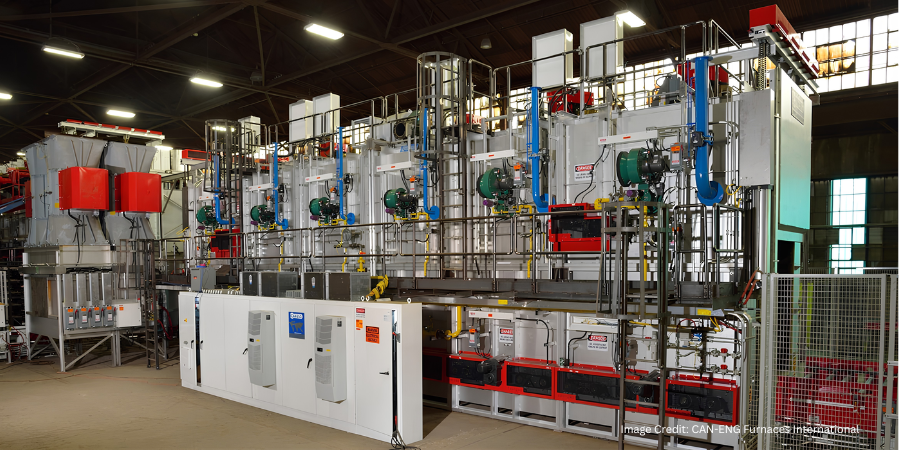
Weight is an important factor because the movement can occur several hundred times each day and, in some cases of high production, even several thousand times per day. For example, during induction surface hardening of track shoes for earth-moving machines that often specify deep hardness case depths (up to 24 mm), it is much easier to move the inductor around the workpiece instead of moving the track shoes, the weight of which can exceed several thousand pounds. (Figure 1)
When moving the inductor, both flexible cables and hoses are used or the inductor is hard-bused to the transformer and the transformer or heat station moves with the inductor. In some cases, the power supply itself may be moved at a moderate rate to scan a stationary workpiece [1]. Another example of moving the inductor is surface hardening of trailer axles. (Figure 2)

The length of the part to be heated is also an important consideration When a component is of moderate weight, it is obviously preferable to move the part rather than the inductor. For example, it is much easier and more cost-effective to design a hardening system that anticipates moving a workpiece that weighs less than 0.25 kg (<0.5 lb) rather than moving an entire power supply, as it is shown in Figure 3.

In other cases, it may not be practical to move very large and elongated components. It would consume too much floor space to move the part through a stationary inductor. In the case of low production rates, the best choice might be to move the inductor, but the length of the high-frequency power leads could become a problem with respect to voltage drop and power loss. In this case, it is preferable to move the inductor with the power supply attached. Then, the moving cables are operating at a low frequency (50–60 Hz) with lower voltage drop and power loss. In the case of high production, continuous horizontal systems may be more suitable.
The consideration of the length of the leads (e.g., cables or buses) from the power source to the inductor is important. They should be as short as possible to conserve energy and to allow the power source to operate properly without reaching any limits (for example, voltage limit). If these leads are too long, the inductance increase can be so significant that it may result in a substantial power loss and voltage drop. The voltage drop in the leads may even exceed the voltage at inductor’s terminals. Long leads could net an excessive total needed power, a measurable reduction in energy efficiency, and potential concerns regarding the process repeatability owing to the possibility of an appreciable inductance change of the flexible leads during their motion, that in some cases may negatively impact process repeatability.
Whether moving the inductor or moving the part, the induction system can be designed to be efficient and robust in order to ensure smooth and consistent operation and the production of quality parts.
I recommend Reference #1 to readers interested in further reading on this subject.
References
- V. Rudnev, D. Loveless, R. Cook, Handbook of Induction Heating, 2nd Edition, CRC Press, 2017.
Dr. Valery Rudnev, FASM, IFHTSE Fellow, is the Director of Science & Technology, Inductoheat Inc., and a co-author of Handbook of Induction Heating (2nd ed.), along with Don Loveless and Raymond L. Cook. The Handbook of Induction Heating, 2nd ed., is published by CRC Press. For more information click here.