VACUUM FURNACES TECHNICAL CONTENT

Keeping Up With Vacuum Furnaces: Balancing What You WANT With What You NEED

OCYou can’t always get what you want. With frequently changing specifications and a volatile economy, what heat treaters want is always evolving. But what they need changes, too. Steven Christopher of Super Systems, Inc. discusses how to balance what vacuum furnace operators NEED and what they WANT. Is the difference between those two things too great?

This article originally appeared in Heat Treat Today’s March 2022 Aerospace print edition.


Steven Christopher
West Coast Operations Manager
Super Systems, Inc.
Photo Credit: Super Systems, Inc.

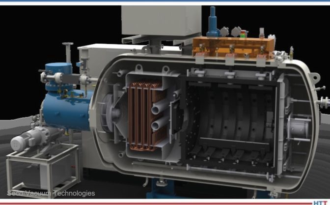
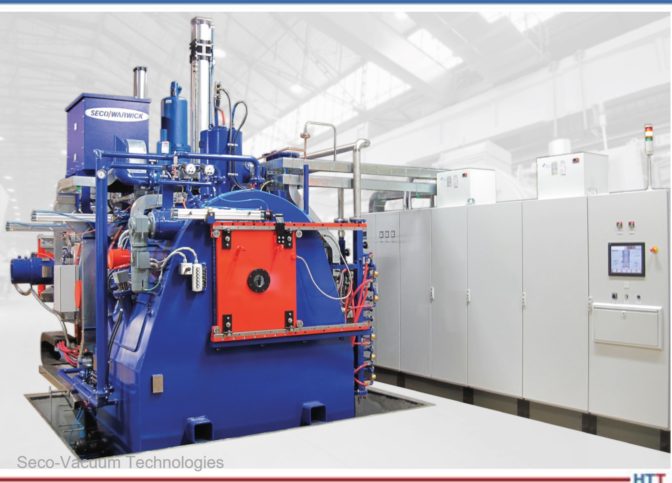
I love metaphors and think of vacuum furnaces as automobiles. As an owner, the goal is to keep our cars on the road for 100,000+ miles — and why not the same for furnaces? Accomplishing this feat requires the same in both cases: (1) routine maintenance — literally changing oil and (2) addressing warnings before they become problems — such as check engine lights or vacuum leaks.

The similarities stop there, however, with a key difference in how each is upgraded. In the near future, if you want a self-driving vehicle you will have no choice but to turn in the keys of your 10-year-old sedan and buy a shiny new Tesla, opting for the autonomous driving upgrade.

But what about your vacuum furnace? As the industry releases all these new standards and specifications, do we also need a newer furnace? Or can we retrofit what we have? That answer is complicated because so much is influenced by what we WANT versus what we NEED.

Day-to-day production shapes what we want. We learn from both experiences and failures, shaping features we want to improve operations, customer experience, and reduce rejected work. Specifications and customers drive what we need. Most recently AMS2750F (and 2769C) have been revised and place a burden on operating aging equipment while maintaining compliance. Before these, NFPA86 was modified in 2019, improving furnace design and safety “best practices."

These requirements levy real costs in terms of both hardware investment and increased labor (additional quality employees). We are expected to perform additional labor with the same workforce; however, the reality is that a worsening domestic labor shortage often means we are doing more work with even fewer people. This article navigates this delicate balance, maximizing each investment dollar’s impact while reducing our reliance on labor.

What We Need

It becomes impossible to completely address such large specifications in a short article, so let me highlight a few important considerations from AMS2769C:

  • Section 3.2.3.2 requires decimal precision for thermocouples (AMS2750F)
  • Section 3.2.4.1.2 outlines leak-up rate requirements
  • Section 3.3.1 reviews partial pressure and dew point requirements
  • Section 3.5.2.1 addresses permissible outgassing
  • Section 3.5.3 covers load thermocouples

Perhaps the most talked about change is the requirement of thermocouples to record to a tenth of a degree. It is important to distinguish the difference between a temperature controller and recorder. Section 3.2.3.2 does not require a furnace to control with decimal precision, only record to it. However, best practice lends itself to controllers supporting this ability as well.

Figure 1. Maximum permissible leak rates
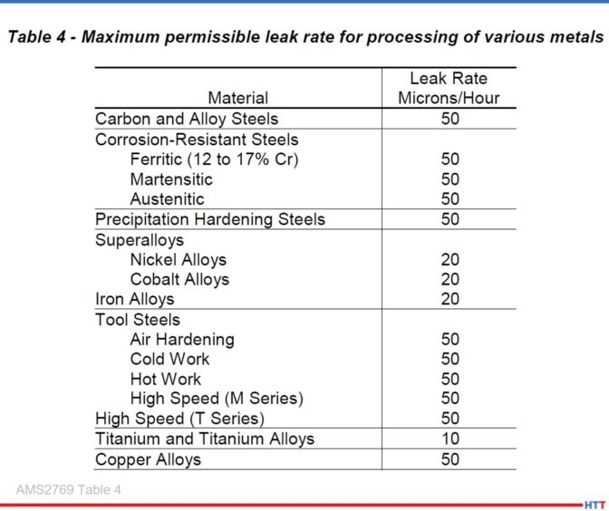
Photo Credit: AMS2769 Table 4

Exposure to oxygen at elevated temperatures is detrimental to part metallurgy, be it aesthetics or integrity. Leak-up rates are so important because they prove such exposure is eliminated (or significantly reduced). AMS2769C attempts to mitigate this exposure by standardizing the best practices for performing such tests. Leak-up rate tests are required weekly for (minimum) 15 minutes. Figure 1 identifies a maximum allowable leak-up rate based on the material being processed.

Historically this requires an operator to initiate a cycle, stop the evacuation (pumping), then document the beginning and ending vacuum levels by hand. While simple, this requires both time and attention, preventing any operator from performing other tasks.

AMS2769C proceeds by addressing outgassing, requiring ramp/soak controllers to either be placed on hold or to disable the heating elements if the vacuum level exceeds (1) the partial pressure target or (2) the diffusion pump operating range. Aging controllers require well-trained operators, constantly monitoring vacuum instrumentation and manually adjusting the controller. This introduces potential for operator error, again limiting their ability to perform other tasks.

Section 3.5.3 details placement and requirements for load thermocouples. Assuming load thermocouples are required, runs may be rejected should thermocouples fail below the minimum processing temperature. Disconnected control systems monitor load thermocouples using a recorder separate from the ramp/soak controller. This complicates the control system’s ability to alert operators to such failed conditions — the recorder not knowing which thermocouples are required.

AMS2769C progresses to cover partial pressure. Partial pressure has been automated for years with minimal changes to control mechanisms, though some have replaced solenoid valves with mass flow controllers (MFCs). System upgrades should strongly consider automatic gas type compensation and digital communications of vacuum levels.

Thermocouple (or pirani) vacuum sensors estimate the heat emitted from a heating filament within the sensor. This measurement represents an exact vacuum level, though the gaseous media separating the fi lament from the measuring tip influences the reading (thermodynamics heat transfer). This phenomenon (represented in Figure 2) explains why nitrogen and argon result in very different vacuum estimates.

Figure 2. Gas compensation graph
Photo Credit: Televac MM200 User Manual

NOTE: Thermocouple gauges operate in vacuum ranges where enough gas molecules remain (e.g., in excess of 1 micron) to influence this reading; unlike cold cathode sensors which operate under complete vacuum, excluding them from such compensation.

As an example, consider a vacuum furnace operating under nitrogen partial pressure. The vacuum instrument correctly displays 200 microns (refer to the AIR curve). Now consider the same cycle, only the operator introduces argon. The display now incorrectly displays (and controls to) 200 microns; however, the furnace is truly operating closer to 100 microns (refer to the ARGON curve).

Figure 3. Dew point requirements
Photo Credit: AMS2769 Section 3.3.1.1

Historically vacuum signals have transmitted a 0-10vdc analog signal representing the vacuum level. As with all analog signals, error is introduced by both the accuracy of the instrument generating the signal as well the recorder interpreting it. This error is mitigated by routine calibrations — often aligned with temperature uniformity survey (TUS) schedules. Modern control systems replace such signals with vacuum instrumentation supporting digital communications, eliminating error in the process. As a bonus, the reduction in calibration points reduces time when performing calibrations. Such systems may even automatically compensate thermocouple sensors resolving the sensitivity of thermocouple sensors to multiple gas types.

AMS2769C references other specifications, namely AMS2750 and the Compressed Gas Association (CGA). CGA establishes minimum requirements ensuring inert gas quality. In addition to supplier certification, gas quality is proven by dew point. All gasses have a dew point, with outside air relatively high (e.g., +50°F) and inert gas very low (e.g., -100°F). Purchasing supplier certified gas results in a facilities bulk storage tank having a very low dew point, with any leaks in gas delivery system (pipe threads, fittings, etc.) resulting in a less negative dew point. The concept that dew point can only raise once exiting the storage tank illustrates the importance of sampling “as the gas enters the furnace” — measurements taken upstream fail to detect leaks downstream. The intensity of this increase directly correlates to the amount of air (oxygen) entering the gas supply, compromising the gas purity, which as previously discussed negatively impacts the parts being processed. Proving a dew point below -60°F proves the inert gas mostly free of oxygen. Measurements have long been a manual process; an operator samples gas using a portable sensor and records the findings in an entry log. Modern systems seamlessly integrate dedicated sensors continuously sampling gas quality which alert upon compromised gas.

What We Want

This article’s first draft opened this section listing a handful of features — that was November. Fast forward three calendar months (what feels like an entire year), it is now January, and priorities have changed. Three months ago we wanted features, now we just want parts. The growing supply chain disruption is feeling less temporary and more permanent. This final draft opens with availability. Any upgrades should factor both (1) component lead-time and (2) their flexibility. Lead-time should focus not just on immediate project delivery, but the long-term availability of the product. Is it in its infancy? Or near the end of its life? What is the current lead-time and strategies to maintain inventory? Flexibility should focus on limitations of the product. Is it limited to specific applications? Or can it be used in other equipment? Flexibility paired with planning results in standardization. Keeping with the automobile theme, standardization is what made Henry Ford’s Model T so special. Standardization reduces on-site spare parts, as the same component can be installed in many locations. Standardization should be a primary focus when purchasing programmable logic controllers (PLCs), vacuum instruments, and temperature controllers.

As if the supply chain worries are not enough, the U.S. faces a labor shortage projected to worsen over the next decade. This highlights another late addition to this article, stressing the importance that any upgrade considers the availability of the most important resource: people. New furnaces and upgrades alike (like it or not) develop a co-dependence between multiple parties. This relationship may be internal, between operations and engineering; or external, between an end user and a supplier. No matter the specific situation, all parties should discuss availability and access to information. Failure to discuss this early on is often exacerbated, especially when upgrades are performed by a supplier who is considered (1) unresponsive or slow to respond and (2) unwilling to share information. Purchase orders should document expectations in terms of deliverables (PLC logic, schematics, etc.) and support.

Figure 4. Projected US labor deficit
Photo Credit: US Department of Labor

This third paragraph was that ill-fated November draft’s first. Today’s buzzword, the Internet of Things (IoT ). As we are well on our way to the quarter mark of the 21st century, we have all become accustomed to a lot of quickly accessible information. Why should vacuum furnace recorders not meet the same lofty expectations? Control system upgrades should be capable of recording information and displaying it in an easily retrievable format. Recorded data should expand beyond the required process data into the status of the furnace itself (valve position, state of limit/thermal/vacuum switches, motor status, etc.). Such data can be evaluated postmortem to troubleshoot a failed production run’s root cause of the failure. Advanced systems should be able to notify personnel of issues via email or text messaging.

Often the information gathered above is passed into a Supervisory Control and Data Acquisition (SCADA) System. This system must meet industry compliance for data integrity and security. As every new software seems to have its own system, daily operation requires most to juggle many of these systems, often sharing common data. A SCADA System should be designed to operate in this unknown environment and be capable of sharing data between itself and Enterprise Resource Planning (ERP) and other supervisory systems. The first step here is to build upon common platforms; and today the most widely accepted platform is Microsoft SQL Server. SCADA Systems should be able to “offer up” data using any number of industry standard protocols (Modbus, API, OPC, etc.).

The biggest invisible threat to our industry is internet security. For those fortunate enough to have avoided a cybersecurity attack, IT’s work seems a burden. For those unfortunate to have experienced such an event, IT’s work is beloved. This rapidly changing frontier is our reality and programs like Cybersecurity Maturity Model Certification (CMMC) become a necessary (even required) precaution. Hardware for upgrades should be vetted for compliance with these evolving precautions.

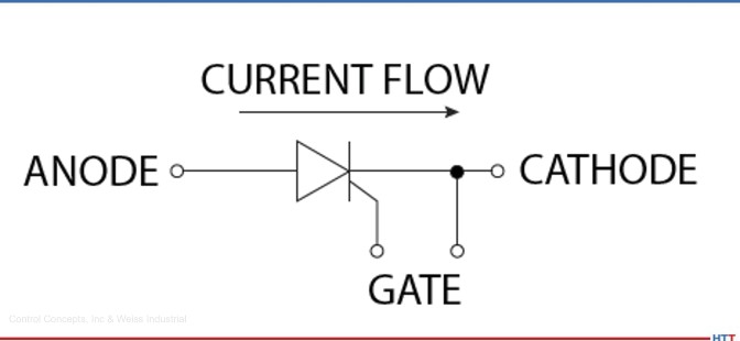
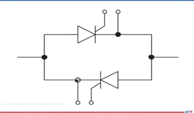
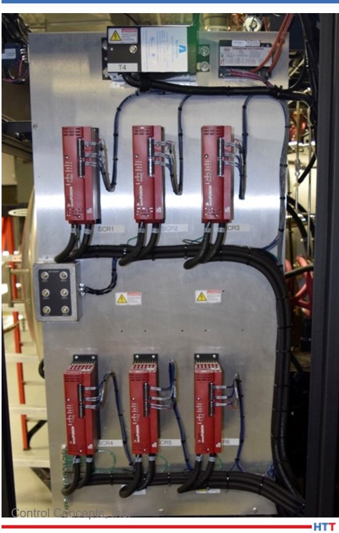
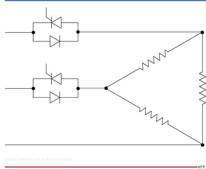
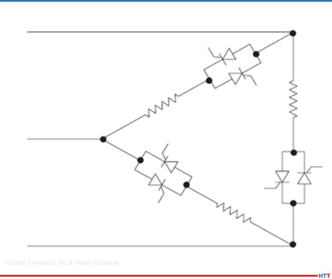
Thus far this article has focused on people, hardware, and features. I now turn the focus to the vacuum furnace itself. Furnaces routinely struggle with passing TUS at both lower (<1000°F) and elevated (>2000°F) temperatures. The issue itself varies between graphite and molybdenum hot zones but the root cause remains the same: inflexibility with rheostats to adjust across a wide temperature range or the furnace’s incapability of reaching elevated temperatures. Users manually adjust the applied power to each zone in attempt to minimize the difference between the coldest and hottest TUS thermocouples. Rheostats force the user to settle for a configuration “just good enough” for all temperatures but “not perfect for any.” Modern systems replace rheostats with individual silicon controlled rectifiers (SCRs) driving each variable reactance transformer (VRT), a feature commonly called digital trim. All furnaces are candidates for digital trim, though older VRT packages using slide wire (or “corn cob”) resistors may require the addition of direct current (DC) rectifiers in addition to SCRs. The benefit of digital trim is these settings can automatically adjust with temperature allowing for the ideal configuration at every temperature.

How Do We Get There?

Resurrecting the automobile analogy which opened this article, have you ever wondered why so many people love Jeep Wranglers (and I realize Jeep could easily have been Harley Davidson or a new home purchase)? The reason is not what they are, rather what they can become. Owners see upgrades and features in their mind long before anything is modified. The key concept here is customization. This same vision applies to vacuum furnaces, any upgrades should consider robust and powerful control systems, flexible enough to evolve with the industry.

PLCs and process instrumentation should always be sourced with room to grow. Modular designed platforms easily expand to integrate new hardware. Ask suppliers how their hardware handles additional inputs, outputs, and sensors. Instrumentation should be integration-friendly and be capable of monitoring the entire vacuum ecosystem — considering the temperature, load thermocouples, and vacuum and gas control systems. Ideally, instrumentation will communicate with each other, passing relevant information between each while simultaneously eliminating calibration points.

Control systems should be sourced with an Evolution Plan in place; compliant solutions today in no way assure compliance tomorrow. Suppliers should be asked their plan for AMS2750G, H, and I. Doing so positions you to make large investments once, then grow hand-in-hand with the industry rather than fight it every time it changes.

Summary: Have a Plan

Modern controllers consolidate a furnace’s self-contained subsystems (vacuum, load thermocouples, valve control, etc.) into a singular control system. This provides the transparency necessary for the controller to alert operators or place itself on hold when necessary. The outcome is that operators require less time monitoring the subtleties of production, meaning they focus their time on more urgent tasks. A happy byproduct becomes the natural progression of data (the recorded values from all these subsystems) into information (meaningful, document values presentable to customers, reviewable by auditors, or referenced for troubleshooting).

I was once told to either open or conclude an article with a poignant quote, so let me offer this advice: When considering upgrades for any furnace “have a plan or become part of someone else’s.” Early conversations between engineers/suppliers and quality/production ensures the delivered product shares everyone’s goals.

About the Author

Steven Christopher is a Purdue University engineering graduate and a 15-year veteran of the heat treating industry. He began his career in pharmaceutical maintenance before joining a commercial heat treat facility focusing on the automotive and aerospace industries. He now manages Super Systems' West Coast operations supporting all types of industries west of the Rocky Mountains.

For more information, contact Steven at schristopher@supersystems.com


Find heat treating products and services when you search on Heat Treat Buyers Guide.com


Keeping Up With Vacuum Furnaces: Balancing What You WANT With What You NEED Read More »

Don’t Vacuum-Braze Metals Containing Zinc

Source: Kay & Associates Brazing Consultants 

Are you sure you should vacuum braze that? As the title of this best of the web article suggests, vacuum brazing materials containing zinc is not a good idea. Volatized zinc can contaminate, and maybe even ruin, your vacuum furnace. But what about cadmium, lead, chromium, and magnesium? Is vacuum brazing safe for those materials?

In this article by Dan Kay, examine the vapor pressure curves of common metallic elements to be sure you know exactly when you need to worry about vaporization. And remember, operating your furnace at partial pressure does not offset the effects of vaporization.

An excerpt: 

Many people braze stainless steels (which contains chromium) at vacuum levels approaching 10-5 Torr [. . . ] You can readily see that at 10-5 Torr the temperature at which Cr volatilizes has dropped down to only about 1800F (950°C). Since nickel-brazing of stainless typically takes place at about 2000-2100°F (1095-1150°C), please understand that you will indeed be volatilizing chromium during this brazing operation, which will condense on the furnace walls, giving them a greenish/bluish coloration.

Read more: Don't Vacuum-Braze Metals Containing Zinc

Don’t Vacuum-Braze Metals Containing Zinc Read More »

“The Die is Cast”: What’s NADCA 207?

Source: TAV VACUUM FURNACES

When "the die is cast," heat treaters should make sure that they're using NADCA 207 standards. Prepared by the North American Die Casting Association (NADCA) for its members, they provide recommendations on how to produce dies for die casting to optimize thermal tool life in terms of thermal fatigue.

In today's best of the web article, check out what some of the essential requirements are and how this standard could help in "maximizing the resistance of tools to the occurrence of cracks from thermal fatigue."

An excerpt:

However, the content of this specification is so well processed that it is valid not only for the production of die casting dies and for thermal fatigue, but also for many other applications, and is the best information material for commercial vacuum heat treatment plants, tool shops and die casting foundries, enabling the elimination of fundamental errors in the tool making process.

Read more at "DO YOU KNOW WHAT NADCA 207 IS?"

“The Die is Cast”: What’s NADCA 207? Read More »

A Layman’s Guide to Understanding the Theory of Gases

Source: VAC AERO International, Inc.

Need a refresher course on the "gas laws" and how they relate to heat treating? What exactly is going on at a molecular level in your vacuum furnace? This best of the web article gives a helpful review of the theory of gases and practical tips to make your heat treating experience easier.

An excerpt:

"The movement of gases is an important and interesting subject but one often dismissed as a topic best left to scientists. However, the Heat Treater needs to know something about the basic nature (theory) of gases and in particular how they behave in vacuum. The main difficulty is that too much theory tends to become a distraction. Our focus here will be to better understand what goes on inside a vacuum furnace."


Read more: A Layman’s Guide to Understanding the Theory of Gases

A Layman’s Guide to Understanding the Theory of Gases Read More »

Avoiding Diffusion Bonding of Parts and Fixtures: A Case Study

OCAs most heat treaters know, parts and fixtures often do not mix well. Diffusion bonding can cause the two to fuse together. In this case study, learn how combining thin-film coatings with specific part and fixture design can avoid diffusion bonding. 

Read all about it in today's Technical Tuesday feature, written by Jeff Tomson, sale manager at IonbondThis article was originally published in Heat Treat Today’s December 2021 Medical & Energy print edition.


Jeff Tomson
Sales Manager
Ionbond

A client approached Ionbond looking for a solution to a problem: They had parts diffusion bonding to their fixtures during heat treatment. The client was using 316SS fixture spacers for heat treating 17-4 SS components at 1904°F (1040°C) in a high-vacuum heat treatment furnace and 316L SS components at 1652°F (900°C) in a high-vacuum heat treatment furnace. Due to the chemical affinity of the alloying elements of the two materials, the length of the heat treatment, and the operating temperature, atoms from both materials could intersperse. The resulting diffusion bonding caused difficulty getting the subject parts to separate from the fixtures.

The coating solution needed to be chemically inactive at the processing temperature while providing a defect-free contact surface. Ceramic materials satisfy these requirements; thus, Ionbond's CVD 29 (Al₂O₃) coating was recommended. The CVD process is a method for producing low stress coatings by means of thermally-induced chemical reactions. Typically, the substrate is exposed to one or more precursors such as TiCl₄, CH4, or AlCl₃ which react on the substrate material to produce the desired film. CVD coatings typically do not maintain their characteristics at the elevated temperatures of our client's application for long periods. However, the high-vacuum environment would allow the coating to function above its 1832°F (1000°C) service temperature. The coating has an excellent record in high temperature applications (cutting, forming, etc.) since it is chemically inert and has the ability to maintain a high hardness.

CVD equipment by Bernex

The CVD 29 coating has different variations and many applications. In the cutting tool world, its ability to resist thermal stresses makes it well suited for high-volume machining of mild and stainless steels. In resistance welding it is used heavily for locating pins and splatter guards, as its electrically insulating properties prevent arcing and its high toughness allows for a long life. For high temperature forming, chemical inertness prevents aluminum buildup on die profiles. High wear resistance makes this coating an ideal solution on ferrous and non-ferrous alloys used in hot extrusion and die casting applications. The overall coating thickness varies from 6 to 16 microns, depending on the version being applied as well as the substrate material. The coating produced is multilayered with adhesion-promoting underlayers that are needed to ensure bonding of a ceramic material to steel.

Due to the high coating temperatures, austenitic stainless steel is typically not an ideal substrate for the CVD process due to its low carbon content causing issues with adhesion. It is a better option than martensitic grades as post-coat hardening is unnecessary. Popular substrates for this coating family include carbides, D2, and H13 tool steels. Some exotic materials such as platinum and nickel content alloys are also used for specialized applications in the semiconductor and aerospace industries.

Ionbond's Cleveland team. Ionbond is a global leader in thin-film coatings, which are used to improve durability, quality, functionality, efficiency, and aesthetics of tools and components. Its portfolio includes physical vapor deposition (PVD), plasma assisted chemical vapor deposition (PACVD), chemical vapor deposition (CVD), and chemical vapor aluminizing (CVA) technologies, including a broad range of diamond-like carbon (DLC ) coatings.

Given the nature of the CVD process, typically all surfaces receive uniform coating. In the first trial, the client's spacers were coated utilizing different fixtures to ascertain whether fixturing methods would be a factor. Subsequent client trials revealed no discernable differences.

The first test by the client using the coated parts at 1904°F (1040°C) in a high-vacuum environment was considered a success, with the client stating that the coating performed “excellently.” There was no sign of coating degradation based on the visual appearance and the subject parts were easily removed from the fixtures with no signs of diffusion bonding. The second test was performed at a lower temperature of 1652°F (900°C) and had similar positive results.

Ionbond in Cleveland, OH

Given the success of the first batch, the client ordered another trial. The second set of parts, while made from the same material, were a completely new design. There were three different parts, two that had threads and the third that was a smaller washer shape. Sharp edges can present issues for the CVD process as stresses can build up at the points of the threads and cause the coating to delaminate. The small washers presented their own concerns due to the thin dimensions sparking concerns about excessive movement. Visual inspection after coating showed good adhesion with no delamination, as the threads were not sharp enough to cause issues. The smaller washers also had negligible distortion after coating. The second set of spacers were also tested in heat treatment at 1652°F (900°C) with similar results.

Inspired by these successes, the client is currently having a third set of parts manufactured to further improve the productivity of their fixtures. The geometry of the third set is completely different as our client continues to leverage the performance of the coating with the design for a more efficient fixturing.

About the Author:

Jeff Tomson is the sales manager at Ionbond’s Cleveland, Ohio site. He has been in sales and marketing roles since graduating from the University of Michigan in 1999. He has worked in automotive, aerospace, and thin-film industries.

For more information:

Contact Jeff at Jeff.Tomson@ionbond.com

(216) 704-4395

Avoiding Diffusion Bonding of Parts and Fixtures: A Case Study Read More »

Microprocessor-Based SCR Power Controllers: Making Your Life Easier

OC Precise temperature regulation is undoubtedly the top variable in the industrial process that influences the quality of the final product. Using intelligent power control and predictive maintenance, silicon controlled rectifiers (SCRs) play a major role in temperature regulation and in improving the industrial heat treating process. What are SCRs and how do they improve the industrial heat treat process?

In this Technical Tuesday feature, written by Tony Busch, sales application engineer at Control Concepts, Inc. and Meredith Barrett, manager of Marketing and Business Development at Weiss Industrial, discover how SCRs can help you improve temperature regulation.

(This article was originally published in Heat Treat Today’s November 2021 Vacuum Furnace print edition.)


Introduction

Meredith Barrett
Marketing and Business Development Manager,
Weiss Industrial

Tony Busch
Sales Application Engineer
Control Concepts, Inc.

In manufacturing metals and in the heat treat industry, temperature regulation is crucial. SCR power controllers regulate the flow of electricity from the grid to a major heating element in a manufacturing process. Usually, the major heating element is a furnace, kiln, or oven, and the SCR is often connected to the heating element directly or to a transformer connected to the heating element.

The ability to calculate resistance in a furnace can provide information on the overall condition of an element. The SCR collects data and communicates it back to the network. Predictive maintenance is knowing when an element has reached its useful life. This article will define what an SCR power controller is, how it functions, and the different firing modes.

Digital Thyristor/SCR Power Controller Overview

“Thyristor” is a Greek-derived word for “door.” The term is a hybrid of the word thyratron and transistor. As defined by ElectricalTechnology.org, a thyratron is a gas-filled tube that works as an SCR. SCR and thyristor are interchangeable terms in describing a device with four semiconductor layers or three PN junctions with a control mechanism. These small machines are known as latching devices. In the context of electrical engineering, a latch is a type of switch where once it’s on, it will remain on after removing the control signal.

Figure 1. Current flow

The actual power control module is an advanced electronic device with LED indicators and I/O terminals. The main internal components of an SCR power controller include:

• Semiconductor power devices (SCRs and Diodes)
• Microprocessor-based control circuits normally referred to as the firing circuit
• Heat sink (a means to dissipate the heat generated from semiconductor devices)
• Protective circuits (fuses and transient suppressors)

The diagram below is a very basic model showing one leg of an SCR controller. However, in all electrical designs of power controllers, such as the popular Control Concepts MicroFUSION series featured in this article, each controlled leg requires SCRs back-to-back within the power control module because of alternating current.

Figure 2. Basic model of one leg of SCR controller

How are Digital SCR Power Controllers Superior to Their Analog Predecessors?

“Digital” SCR power controllers are basically a concise way of referring to a power controller unit that utilizes a SCR switch (as opposed to a different switching method such as an insulated-gate bipolar transistor (IGBT)) and has all the above components. Additionally, these units contain microprocessors that make them more of a smart device. They are scalable, and easily paired with other digital units, whereas pairing analog power controllers results in potential emitter gain and bias.

Digital SCR power controllers can provide flexibility unmatched by analog units. This flexibility includes various communication options and the ability to switch through fi ring modes with ease, all without requiring the unit to be changed or rewired. The adaptable nature of digital SCR power controllers allows them to be incorporated into an industrial heat treat process much more effortlessly.

Older analog units are not highly configurable like their digital replacements. Newer SCRs not only have configurable faults and alarms, but also savable configuration files which can easily be loaded onto another unit.

Digital SCR power controllers can obtain accuracy and repeatability previously impossible with analog controllers. Digital units have power regulation capabilities that adjust for both variations from the mains voltage and resistance from the heating element. This form of power regulation is not only the most precise way to regulate temperature, but it also allows for process repeatability.

Synchronization of two units connected to the same power source, firing in zero-cross mode, is not ideal. This means that modules should not sync up so that they are on and off in unison. If this should happen, the process would require a large amount of current to be drawn from the source while the controllers are all on, and none when they are off.

The company’s SYNC-GUARD™ feature, not previously available on older SCR controller modules, reduces the peak current draw required from the source over time by causing each controller to attempt to find a time to turn on when fewer, or no other, controllers are firing. However, it has its limitations. The more controllers that are added to application, the probability of them syncing increases. Once ten or more controllers are utilized in an application, it becomes impossible to not have some sync up despite this feature.

Another key difference is that digital SCR power controllers are always calibrated and will never change. This allows the convenience of being able to “set it and forget it.” Newer models have an option of a digital display which was previously unavailable with analog controllers.

How the Latest SCR Power Controllers Improve Industrial Furnace Operations

SCRs can calculate electrical resistance in a furnace and provide precise power control. Intelligent power control has embedded algorithms which teach functions to calculate data and predict what is likely to happen next in the life of a heating element. This capability can determine partial load loss, resistance change, and complete load loss.

Partial load fault detection is a “watchdog” feature that monitors the system for change in resistance. This is useful for detecting an element failure for loads with multiple parallel elements. The feature monitors a user-set tolerance value that determines the drift from the target resistance in the system.

Therefore, an operator can enter the resistance manually or use the innovative “teach function” with a digital SCR controller. This is a form of artificial intelligence that will allow the SCR to learn the heating element through algorithms. The teach function auto-ramps and intelligently saves different resistance values at various setpoints in a process, eliminating guess work.

SCR power controller units attached to
industrial furnace

Heater bakeout is an aspect of industrial furnace operations where digital SCRs offer a great amount of control. Industrial furnaces, kilns, and ovens are often lined with some sort of refractory or ceramic material that allows them to withstand extremely high temperatures. Typically, this material can get stressed and crack if heated too quickly, particularly in some submersion heaters where moisture can be present.

Modern SCR power controllers have an actual heater bakeout mode that will increase the temperature to the heating element gradually, allowing the furnace to slowly equalize in temperature. If any moisture is present in the heating element, it is baked away, and either way, slowly ramping up the temperature prevents damage to the refractory. This can prevent both costly furnace repairs and downtime.

Another major advantage of digital SCR controllers is tap change indication that informs the operator when to change voltage taps. Some loads, even if they remain the same, still can influence and change the element resistance over a period of time. Because this affects the power factor, a transformer with multiple voltage taps can be used.

Additionally, digital SCR controllers can also be utilized to achieve a constant output power. The tap change indication feature signals the operator when to adjust the voltage taps to a higher or lower setting on a digital display or digitally via the alarm monitor panel.

Predictive vs. Preventative Maintenance

Predictive maintenance has become a popular buzz word related to “Industry 4.0” as we now enter what is known as the fourth industrial revolution, or digitization of a manufacturing process utilizing an interconnected network of smart devices. The goal of both predictive maintenance and preventative maintenance is to increase the reliability of assets, such as an industrial furnace, oven, or kiln used in the heat treat manufacturing process. This not only avoids costly downtime but increases the life of an asset resulting in substantial savings in maintenance costs.

The main difference between the two is preventative maintenance is simply regularly scheduled upkeep, such as a temperature uniformity survey (TUS) on an industrial furnace. Think, for example, of how you have the oil changed every 3,000 miles in your vehicle because it is common practice for extending the life of your engine: that’s preventative maintenance.

Predictive maintenance is more condition monitoring or intelligence gathering on the health of an asset. It is based on present time and continuous data monitoring from smart devices on an industrial network. Predictive maintenance is knowing when an element needs to be fixed or has reached its useful life and needs to be replaced. Knowing the life of the element allows for a structured shut down preventing expensive unscheduled downtime.

How Do SCRs Achieve Intelligent Power Control?

In the instance of intelligent power control, the SCR acts similarly to a dimmer switch on a lighting fixture. It regulates the amount of electricity going into the furnace, just like the dimmer controls the amount of brightness going into the light bulb. The purpose of regulating the electricity to the heating element is to maintain the desired temperature and prevent damage to the asset from power surges or voltage inrush.

“Resistance” is an electrical engineering term that relates to the amount of current that can flow through a heating element of a furnace, machine, or other electronic device that heats up. Technically, this can be something as simple as your household toaster. When the heating element is cold, the resistance to electricity is lower, allowing more current to pass through. When it is hot, its resistance is higher, blocking the incoming current.

Figure 3. AC supply (left) and load voltage (right)

Both variations in the electricity coming from the grid (the mains voltage) and furnace resistance can cause temperature fluctuations. SCR power controllers accommodate for both variations from the mains voltage and furnace resistance by regulating output current utilizing different firing modes.

Firing Modes of SCRs: Phase-Angle & Zero-Cross Explained

What technically is a “firing mode” when it comes to SCRs? As noted in the SCR diagram, the topology of an SCR includes a control circuit also known as a “firing circuit.” The SCR has feedback and logic to determine how it is going to fire the electric sine wave. Thyristors, as SCRs are more commonly known outside of the U.S., have two basic control modes: phase-angle and zero-cross.

Phase-Angle

When a SCR power controller adjusts the voltage using the firing angle, it is known as phase-angle mode. This is analogous to a dimmer switch on a light fixture. The SCR is acting as a dimmer switch on an industrial furnace. Using phase-angle control, each SCR in a back-to-back pair is turned on for a variable portion of the half-cycle that it conducts. This trims every single half sine wave, giving a very smooth output, hence getting the correct kilowatts to the needed load.

In a heat treat application where the SCR is firing directly into the transformer, phase-angle mode will need to be employed. This protects the transformer from saturation. (See Figure 3.)

Zero-Cross

In zero-cross firing mode, the power controller adjusts the duty cycle to regulate the voltage. Each SCR is turned on or off only when the instantaneous sinusoidal waveform is zero. In zero-cross operation, power is applied for several continuous half-cycles, and then removed for a few half cycles, to achieve the desired load power.

In other words, zero-cross is best described as a blinking on and off. You’re firing a certain amount of full wave cycles, then it is going to turn off for a period of time, and then return to the on mode. An average is taken of the cycles that fire versus do not fire, which gives you control.

The on and off nature of zero-cross is beneficial for power factor, and the overall cost is lower than running SCRs in phase-angle applications. Simply stated, running SCR power controllers in zero-cross mode versus phase-angle mode consumes less energy and saves money on the electric bill. Zero-cross also produces little to no harmonics. As illustrated below in Figure 4, you can run SCRs in two-phase versus three-phase mode using zero-cross. If the resistance is varying less than 10%, zero-cross can be applied to the heat treat process.

SCR Power Controller Configurations

Single-Phase

In a single-phase configuration, SCRs are running back-to-back to the load, which is looping back up to L1 and L2. This is the most basic SCR set up.

Figure 4. Single-phase configuration

Three-Phase/3-Leg (6SCR)

Three-phase is wired in a delta or wye and involves three SCR modules connected in a circuit. This is great for phase-angle control where the SCR is firing into transformers. The topology is beneficial for direct firing as well. Three-phase is effective in high inrush current loads that require a current limit, and it also enables the system to phase without blinking on and off.

Figure 5. Three-phase/3-leg (6SCR) configuration

Three-Phase/2-Leg (4SCR) Zero-Cross Only

This configuration involves two SCR modules controlling two of the legs, and the third leg is connected to the delta or wye but going directly back to supply voltage. This can be more cost effective for an application since it is run in zero-cross mode.

Figure 6. Three-phase/2-leg (4SCR), zero cross mode

Inside Delta

Inside delta configuration is double the wiring. However, it reduces the size of the SCRs needed. Where the SCRs are placed in the circuit in the inside delta configuration will draw less current at the point. This is a more uncommon configuration, and it is found infrequently in the field.

Figure 7. Inside delta configuration

What SCR Is Right For Your Application?

Weiss Industrial, a manufacturer’s representative company, chose to partner with one of the top OEMs to help provide their customers with uninterrupted and efficient plant operations. They teamed up with Control Concepts Inc. (CCI) on their MicroFUSION Power Controllers because they found their product to be the most reliable and their customer service superior. The company’s power controllers are manufactured in the USA in their 54,000 square foot, company-owned facility in Chanhassen, MN.

Tony Busch, sales application engineer, notes that one of the bigger factors to consider in selecting the right SCR power controller is the load type. Some loads require zero-cross fi ring modes, others phase angle only, and in certain cases it does not matter. It can be either zero-cross or phase angle.

The main rule of thumb is to never use zero-cross on fast responding loads, such as infrared lamps and low mass heaters. In this instance, zero-cross will cause too much of an inrush current and can burst lamps and/or fuses down the line. On the other hand, loads in which the resistance changes are less than 10%, such as nickel and iron chromium, zero-cross must be used. Operators also prefer zero-cross in instances where low harmonics are required, as it produces less harmonics than phase-angle firing mode.

Conclusion

In conclusion, SCRs help achieve an integral part of an industrial network that improves the modern heat treat manufacturing process by providing precise and intelligent power control. They also achieve predictive maintenance previously impossible with their analog predecessors. Their advantages are numerous in improving industrial furnace operations and the heat treat manufacturing process.

Other major advantages of SCRs are their high reliability. Since they are solid-state devices, there is no inherent wear-out mode that can be associated with other industrial mechanical machinery that has gears or moving parts. This means little to no maintenance of the SCR power controller.

They have infinite resolution, which means if there is an incoming supply voltage of 480 volts, sequentially, 480 volts will be returned out of the SCR when it is turned on fully. There is no trim back or load loss involved. You can go from zero to 100% if you want to control your voltage, power, or current.

SCRs also have an extremely fast response time, which allows the operator to turn the device on and off very quickly. In North America, voltage is mostly running on 60hz at 120 half cycles per second. SCRs allow you to target a particular half cycle and turn it on and off very quickly. This is a great feature for loads that have high inrush current, acting as a soft starter, to keep from saturating the heating element.

Want to learn more?

Weiss Industrial has partnered with Control Concepts Inc. to produce a PDF document entitled A Guide to Intelligent Power Control & Temperature Regulation Utilizing SCR Technology, which you can obtain by contacting Meredith Barrett, Marketing and Business Development manager at Weiss Industrial: meredith.barrett@weissindustrial.com.

About the Authors: 

Tony Busch, a graduate of Dunwoody College of Technology with a degree in Electrical Construction, began his career at Control Concepts, Inc.’s headquarters in Chanhassen, MN as a test technician, quickly transitioning to field service and repairs. In 2014, he began his current position as a sales application engineer and became Bussmann SCCR training certified. Contact Tony at tony.busch@ccipower.com

Meredith Barrett has a Communications degree from Penn State University and over twenty years of experience in sales, corporate communications, marketing, and business development. While her journey into the industrial and manufacturing sector began in 2014 with Siemens Industry, Meredith joined Weiss Industrial in January of 2020 as the Marketing and Business Development manager to assist in building a new marketing department and lead generation program, while also supporting business development. Contact Meredith at meredith.barrett@weissindustrial.com.

Microprocessor-Based SCR Power Controllers: Making Your Life Easier Read More »

A Guide to Selecting Heat Treating Equipment

OCDo you always feel confident when selecting heat treating equipment? ¿Se siente siempre seguro cuando selecciona equipos de tratamiento térmico?

There are many factors involved when making a purchase. Often, key considerations may be missed. Read this guide on how to select and buy new equipment by Carlos Carrasco, founder of Carrasco Hornos Industriales.

This original content article was originally published in Heat Treat Today’s November 2021 Vacuum Furnace print edition in English and Spanish.


Carlos Carrasco
Founder
Carrasco Hornos Industriales

Why Is This Guide Helpful?

There are many reasons to select industrial furnaces carefully. One is the cost of the furnace. Another is realizing heat treating will affect the product and the bottom line. There is more specialized engineering in heat treating equipment than is apparent from the outside.

The purpose of this guide is to help engineers make the best equipment selection. The decision will affect not only the project, its budget, and results, but will also reflect the buyer’s knowledge. After the heat treating equipment is selected, the realization may occur that perhaps insufficient thought was given to potential maintenance problems or the work required to keep it in top working condition.

The following steps, gathered from more than 50 years of experience in the fields of manufacturing, sales, and maintenance, will be a useful guide to selecting heat treating equipment that will please both management and operators.

Vacuum high-pressure hardening furnace

Step One: Quote Request

When requesting a quote, management knows the exact requirements the heat treated products must have. A reliable supplier should be able to understand all requirements for a quote. Requests must be clear, concise, and contain at least the following information:

  • Heat treating processes that will be carried out on the equipment
  • Shape, general dimensions, and weights of the product(s) to be heat treated
  • Production volumes per hour, day, or month
  • Number of hours available for heat treating
  • Part material
  • Fuel type, or if the heating will be done with electricity
  • Voltage available in the plant
  • Space available for installation of equipment
  • Special considerations for handling loading and unloading

Furnace manufacturers need the above information to begin to create a series of options for the equipment that will be most suitable for the required processes. For example, hourly production defines: the dimensions of the space to heat the load, the type of furnace (continuous or batch), the amount of heat to be released in the furnace, the loading and unloading method, and the devices for accommodating or transporting the load such as trays, baskets, or conveyor belts. All these considerations influence both the initial cost and the operating cost, because in the end, the cost of the proposed equipment and its functionality are directly related to the specifications of the request for a quote.

It is difficult to attempt to use one furnace for all heat treating processes or to attempt to take into account future production needs that may not be necessary. It is impractical to carry out several processes that require different temperatures or have different production volumes. Trying to do so leads to oversized and over-budget equipment.

Vacuum low-pressure carburizing furnace

Step Two: Supplier Selection

Quote requests should only be submitted to manufacturers with the technical capacity and experience to prepare an offer that satisfies the request. Always use references from previous installations with similar quote requirements.

Considering the potential for financial gain, the cost of heat treating equipment can be appealing. The design and construction of heat treating equipment involves a considerable amount of engineering resulting from expensive investments in research and development. This research and development is influenced by user feedback detailing equipment failure. This feedback creates opportunities for manufacturers to fix equipment issues. Without the added benefit of other heat treater’s feedback, equipment failure is more likely. Finding a manufacturer with experience is crucial.

Only suppliers with experience and solid technical capacity will be able to guarantee results from the start. The goal is to receive equipment that requires no corrections after the first load leaves the furnace and to not have to rework the design.

Step Three: Study and Evaluation of Offers

A failed project is too much to risk, and so the responsible supplier will invest time and money in the study and preparation of the offer.

Every responsible supplier has been disappointed by an offer read backwards — when the potential customer reads the price first. Is the overriding need to stay within a certain budget or for heat treating equipment that is capable of processing parts to meet specifications? A careful reading of the offer may justify the cost of the furnace in relation to production needs. If there is a confusing section of the offer, it is important to clarify with the supplier. Investment in production equipment is very important, but it is even more important that the investment be profitable.

The heat treating equipment must satisfy a production need and certain metallographic specifications. Consequently, the dimensions of the space where the parts will be placed may be the main factor in the design of the furnace. This is because metals are only capable of heating up to a certain temperature at a rate that is determined by the heating method, geometry, and load arrangement. Only experienced vendors can make the correct calculations to meet the production needs of the project. Be sure to understand the calculations that lead to the sizing of the proposed system.

How are the parts supported and/or transported within the furnace? This is a point of great importance for the initial cost of these components and for the costs of future maintenance. Keep in mind that any mechanism that works at high temperatures will always be problematic for maintenance and replacement. Cast link belts, for example, have a higher initial cost, but they withstand heavy loads longer than metal mesh belts. However, there is a notable difference in the cost of components made of chromium-nickel alloy and those of carbon steel. Since chromium-nickel materials are able to withstand higher temperatures, their use is recommended and almost essential.

Furnaces tend to deteriorate rapidly where the heat is being lost. Make sure the door design is the best possible to avoid heat loss. Be sure that all doors included in the design are necessary. Doing so will save maintenance costs.

When it comes to quenching, oil or water circulation systems are extremely important, as is tank capacity. Otherwise, the quenching medium may overheat, causing unsatisfactory results.

In an oven intended for low temperature operations 356°F–1,112°F (180°C–600°C), for example tempering processes, it is necessary to have a fan to recirculate the hot air from the furnace. The uniformity of the temperature in the parts and the speed at which they heat up depends on the speed of recirculation, the weight of the air, and the design of the furnace, which must force the passage of air optimally through the load with the use of deflectors, screens, or distribution plenums. In high temperature furnaces, 1,292°F–2,192°F (700°C–1200°C), the heat transfer depends on the radiation toward the load and its exposed surface, so a recirculation fan is not necessary. Heat treatment is a critical process and temperature pyrometers must have the necessary precision.

List any doubts about the offer and ask the supplier to clarify at length in writing. The answers will make it easier to do a second analysis of the offer and compare it with other offers. In addition, the written clarifications will be a record for review by other collaborators on the project. Ask for feedback and observations on the proposals to get a second opinion.

Ask suppliers to provide a list of similar installations. Industry colleagues are generally unbiased in their comments about their experience with a particular supplier.

Finally, make a comparison chart in the most objective way possible. Keep in mind the fact that offers often do not include some subjective issues that may be important for a final selection. For example, some vendors are likely to have greater knowledge and experience in certain processes, simply because they have invested time and money to fi nd the best solutions to the process and those experiences could be beneficial.

Step Four: The Price

Understanding the scope of the received proposals that meet production and quality requirements is not all that goes into selecting heat treating equipment. After all this, there are still significant differences between various suppliers. Price is one of these differences. At this stage, the industrial furnace manufacturer will need to justify costs. It will be easy to tell if the manufacturer is thinking of the buyer as a future satisfied customer, or only of the economic benefits the sale will bring.

Conclusion

There are innumerable cases in which the equipment was poorly selected: “The substation and/or the cooling tower did not have the capacity;” or “The equipment is not what we expected;” or “They never told us that the furnace needed gas in those capabilities.” These are just a few of the possible comments everyone has heard.

Selecting heat treating equipment should be done slowly, analyzing all the options,  weighing the differences between providers, and seeking clarification. Ask the supplier for multiple equipment options like requesting spare parts for the first year of operation.

Ultimately, time will tell if the furnace selected was the right choice. These recommendations provide a guide to making that decision. We sincerely hope that these recommendations will guide you in the selection of industrial furnaces for heat treating.

About the Author:

In addition to being the founder of Carrasco Hornos Industriales — furnace experts, consultants, and independent sales representatives for various furnace companies and spare parts — Carlos Carrasco is the founder and former president of ASM International, Mexico Chapter with more than 50 years of experience in the heat treat industry.

For more information:

Contact Carlos at contacto@carrasco.com.mx or at www.furnacexpert.com

A Guide to Selecting Heat Treating Equipment Read More »

Guía para la Selección de Equipos para Tratamiento Térmico

OC¿Se siente siempre seguro cuando selecciona equipos de tratamiento térmico? Do you always feel confident when selecting heat treating equipment?

There are many factors involved when making a purchase. Read this guide on how to select and buy new equipment by Carlos Carrasco, founder of Carrasco Hornos Industriales. The Spanish version is below, or you can check out both the Spanish and the English translation of the article where it was originally published: Heat Treat Today's November 2021 Vacuum Furnace print edition.

¿Se siente siempre seguro cuando selecciona equipos de tratamiento térmico? Hay muchos factores involucrados cuando se hace una compra. Consulte este artículo para conocer los pautas que lo ayudarán en el proceso de selección y compra. Autor: Carlos Carrasco, fundador de Carrasco Hornos Industriales.


Carlos Carrasco
Fundador
Carrasco Hornos Industriales

¿Por qué es conveniente esta guía?

Este artículo ayuda a los ingenieros a comprar equipos de tratamiento térmico. Hay muchas razones para seleccionar cuidadosamente los hornos industriales. Uno, es el costo del horno en sí y otro, es que el producto que se está tratando térmicamente afectará los resultados de su empresa.

En un equipo para tratamiento térmico, hay más ingeniería especializada de lo que parece en el exterior. Hay varias y muy sólidas razones, para hacer una cuidadosa selección de estos equipos, pues sus componentes son inherentemente de alto precio y en la mayoría de los casos, los resultados del tratamiento térmico tienen un importante efecto en la economía de su empresa.

El objetivo de esta guía es el de tratar de ayudarle a hacer la mejor selección del equipo; porque su decisión afectará no sólo al proyecto, su presupuesto y resultados, sino también a su capacidad como ejecutivo. No será la primera vez que escuche usted comentarios respecto a equipos adquiridos por la empresa en etapas anteriores a la suya o en la misma, y es común en la industria, tanto nacional como internacional, que los operadores o el personal de mantenimiento, comenten: “Cuando adquirieron este horno, nadie pensó en los problemas de mantenimiento [. . .] Como ellos no son los que lo usan día con día, no se dieron cuenta de cuánto trabajo se requiere para mantenerlo o bien para trabajar confi ablemente con él”.

Déjese ayudar, pues como ingenieros consultores en hornos y experiencia de más de 50 años en este ramo; tanto en la fabricación, venta y mantenimiento, con buenos resultados, los comentarios siguientes seguramente pensamos le serán útiles.

Horno de temple al vacío

Primer paso: solicitud de la cotizacion

Al solicitar una cotización, nadie mejor que Ud. puede conocer los requisitos que deben tener sus productos tratados térmicamente. Un proveedor confiable, debe ser capaz de entender todas sus necesidades de tratamiento térmico a partir de la solicitud de cotización que le presente. Consecuentemente, su solicitud deberá ser clara, concisa y tendrá como mínimo los siguientes datos:

  • Proceso de tratamiento térmico a efectuarse en el equipo.
  • Forma, dimensiones generales y pesos del (los) producto(s) a tratar térmicamente.
  • Volúmenes de producción por hora, día o mes.
  • Número de horas disponibles para el trabajo de tratamiento térmico.
  • Material del que están construidas las partes.
  • Combustible disponible o en su caso, si la calefacción será por medio de electricidad.
  • Tensión eléctrica disponible en la planta.
  • Espacio disponible para la instalación del equipo.
  • Consideraciones especiales del manejo de la carga y la descarga.

Es conveniente que Ud. sepa que los fabricantes de hornos necesitan la información anterior para empezar a definir una serie de opciones del equipo que podría ser el más adecuado para sus procesos. Por ejemplo, la producción horaria define: Las dimensiones del espacio para calentar la carga, el tipo de horno, continuo o por lotes, la cantidad de calor a ser liberada en el horno, así como el método de carga y descarga y los dispositivos para acomodar o transportar la carga como charolas, canastillas o bandas transportadoras. Todo lo anterior influye, tanto en el costo inicial como en el de operación, porqué, a fin de cuentas, el costo del equipo propuesto y su funcionalidad, están en relación directa a las especificaciones de su solicitud de cotización.

Ah, y por favor, no trate de llevar a cabo todos los procesos de tratamiento térmico habidos y por haber en un único horno, ni tampoco quiera tomar precauciones de futuras necesidades de producción, de las cuales no tiene ahora ninguna certeza, ya que es difícil llevar a cabo en un solo horno varios procesos que involucran diferentes temperaturas, volúmenes de producción, etc. Un enfoque en este sentido conduce a equipos sobredimensionados y posiblemente fuera de su presupuesto.

Horno de vacío para carburizado a baja presión

Segundo paso: selección de proveedores

Presente su solicitud de cotización, solamente a quien tenga la capacidad técnica y experiencia para preparar una oferta, que satisfaga dicha solicitud. Utilice siempre referencias de instalaciones previas, y de preferencia similares, o mejor aún, iguales a la que usted requiere.

El costo de los equipos para tratamiento térmico es elevado y representa un atractivo a empresas e individuos que consideran la posibilidad de obtener beneficios económicos. La verdad, es que el diseño y construcción de estos equipos involucra una considerable cantidad de ingeniería, resultado de costosas inversiones en investigación y desarrollo con retroalimentación de casos prácticos (los fracasos enseñan) que han sido aprovechados en beneficio de los clientes potenciales. En suma, no permita que sus necesidades sean el método de aprendizaje de un proveedor. Aquí es donde no hay sustituto a la experiencia.

De hecho, el proveedor con experiencia y sólida capacidad técnica es el único que estará en posibilidad de garantizar resultados desde el principio. Desde luego, a Ud. le interesa obtener resultados dentro de especificaciones, desde la primera carga que sale del horno, y no comprar excusas, promesas y retrabajos para corregir lo que de inicio está mal hecho. Quizá, con buenas intenciones, pero poca y en algunos casos, nula experiencia.

Tercer paso: estudio y evaluación de las ofertas

El proveedor responsable invertirá tiempo y dinero en el estudio y preparación de la oferta, porque no puede correr el riesgo de que su proyecto no cumpla su cometido. Ahora la responsabilidad de evaluar las propuestas recae sólo en Ud.

No hay proveedor responsable, que no haya sufrido la decepción de que su oferta sea leída de atrás para adelante. Nos referimos a que el precio es la primera línea que lee el cliente potencial. Hágase una pregunta: ¿Su necesidad primordial es, un precio o un equipo de tratamiento térmico que sea capaz de procesar las piezas para que cumplan sus especificaciones de su tratamiento térmico? La lectura cuidadosa de la oferta, le dará la respuesta a sus necesidades de producción y a la justificación del costo del horno. Si hubiese alguna sección que no sea de su completa comprensión, no dude en llamar al proveedor para que haga las aclaraciones correspondientes. Por favor, no malentienda. La inversión en equipos de producción es muy importante, pero más importante será que la inversión sea rentable.

El equipo para tratamiento térmico debe satisfacer una necesidad de producción y de ciertas especificaciones metalográficas. Consecuentemente, las dimensiones del espacio en donde serán colocadas las partes, quizá sea el factor principal en el diseño del horno. Esto se debe, a que los metales sólo son capaces de calentarse hasta una cierta temperatura, a una razón que está determinada por el método de calefacción, la geometría y acomodo de la carga. Sólo los proveedores experimentados, pueden hacer los cálculos correctos para que su propuesta satisfaga las necesidades de producción del proyecto, del que Ud. es responsable. Solicite al proveedor le muestre y explique la memoria de cálculo que conduce al dimensionamiento del sistema propuesto.

¿Cómo se soportan y/o transportan las partes dentro del horno? Éste es un punto de gran importancia, por el costo inicial de estos componentes y también por los costos del mantenimiento futuro. Conviene tener en cuenta que, cualquier mecanismo que trabaje a alta temperatura, siempre será problemático su mantenimiento y reposición. Las bandas de eslabones fundidos, por ejemplo, (de mayor costo inicial) soportan mejor y durante mayor tiempo, cargas pesadas en comparación con las bandas de malla metálica. Sin embargo, hay notable diferencia en los costos de componentes de aleación Cromo-Níquel, comparados con los de acero al carbón, pero su uso es prácticamente imperativo.

Los hornos tienden a deteriorarse rápidamente en cualquier lugar en donde haya fuga del calor. Asegúrese de que el diseño de las puertas sea el mejor posible para evitar esta fuga de calor y también de que su horno no tenga puertas que no necesita. Esto le ahorrará costos de mantenimiento.

Por lo que respecta al temple, los sistemas de circulación de agua o aceite son de extrema importancia, lo mismo que la capacidad del tanque. De lo contrario, el medio de temple puede sobrecalentarse y los resultados de su proceso, podrían no ser satisfactorios.

En un horno destinado a operaciones de baja temperatura (180 a 600° C), por ejemplo, procesos de revenido, es necesario disponer de un ventilador para la recirculación del aire caliente del horno. La uniformidad de la temperatura en las partes y la rapidez a la que se calientan las mismas, depende de la velocidad de la recirculación, del peso del aire y del diseño del horno que debe forzar el paso del aire en forma óptima, a través de la carga, con la utilización de mamparas deflectoras o plenos de distribución. En los hornos de alta temperatura (700 a 1200° C), la transferencia de calor depende de la radiación de éste hacia la carga y su superficie expuesta, por lo que un ventilador de recirculación no es necesario. El tratamiento térmico, es un proceso crítico en lo que se refiere a temperatura. Los pirómetros reguladores de temperatura deben tener la precisión necesaria.

Escriba sus dudas sobre la oferta y pida al proveedor que las aclare en forma extensa y por escrito. Las respuestas le facilitarán el hacer un segundo análisis de la oferta y compararla con otras ofertas; además, tendrá un registro para revisión por parte de otros colaboradores en el proyecto. Pida opinión sobre sus observaciones a las propuestas, pues uno tiende a pensar en círculos.

Solicite a los proveedores, le entreguen una lista de instalaciones similares a la suya en las que hayan intervenido. Generalmente, los colegas industriales se muestran imparciales en sus comentarios sobre la experiencia que hayan tenido con un determinado proveedor.

Finalmente, haga un cuadro comparativo, en la forma más objetiva posible. No pierda de vista que, frecuentemente las ofertas no incluyen algunas cuestiones subjetivas, que pueden ser importantes para una selección final. Por ejemplo, es probable que algunos proveedores tengan mayores conocimientos y experiencia en ciertos procesos, sencillamente porque han invertido tiempo y dinero para encontrar las mejores soluciones al proceso y Ud. podría verse beneficiado con esas experiencias.

Cuarto paso: el precio

Seguramente, ahora que ha comprendido el alcance de las propuestas que ha recibido y que cumplen con sus necesidades de producción y calidad, se dará cuenta que aún así habrá diferencias entre sus distintos proveedores que podrían llegar a ser significativas.

Este es el momento en que un fabricante de hornos industriales podrá justificar sus costos. Y usted sabrá si ha realizado su oferta pensando en Ud. como un futuro cliente satisfecho o únicamente en los beneficios económicos que la venta le reportará.

Conclusiones

Son innumerables los casos en que los equipos fueron mal seleccionados: “La sub-estación y/o la torre de enfriamiento no tuvieron capacidad”, “El equipo no es lo que esperábamos”, “Nunca nos dijeron que el horno necesitaba gas en esas capacidades”. Estos son sólo algunos de los comentarios que todos hemos escuchado.

Tómese todo el tiempo que requiera para analizar sus opciones, piense el porqué hay diferencias de un proveedor a otro y solicite que le sean aclaradas. Pida a sus proveedores las opciones a las que puede acceder con el equipo que está solicitando y que éstas sean cotizadas como eso: opciones. No se olvide de solicitar las refacciones que pudieran ser utilizadas durante el primer año de operación de su horno.

Para finalizar, sólo el tiempo dirá si al seleccionar sus hornos, éstos funcionaron como se esperaba.

Sinceramente, esperamos que estas recomendaciones le orienten en la selección de hornos industriales para tratamiento térmico y estamos seguros, que así será. Seguro que debe haber más preguntas relacionadas con este tema, no dude en contactarnos para obtener ayuda.

Sobre el autor:

Expertos en hornos. Representantes de diversas compañías fabricantes de hornos industriales, partes de refacción y equipo de combustión. Con más de 55 años de experiencia en la industria y consultores. Carlos Carrasco es fundador y expresidente del capítulo México de la ASM International.

Contacto Carlos: contacto@carrasco.com.mx

Guía para la Selección de Equipos para Tratamiento Térmico Read More »

The Use of Graphite for Vacuum Furnace Fixturing

OC Carbon/carbon composite. What is it? Why is the vacuum furnace industry excited about its use in graphite vacuum furnace fixtures, grids, and leveling components?

In this Technical Tuesday, originally published in Heat Treat Today’s November 2021 Vacuum Furnace print edition, explore this new material game changer and learn about its versatility in this informative article by Real J. Fradette, senior technical consultant, Solar Atmospheres, Inc., and Roger A. Jones, FASM, CEO emeritus, Solar Atmospheres, Inc.


Roger Jones, FASM, CEO Emeritus, Solar Atmospheres, Inc.
Additionally, Real J. Fradette, Senior Technical Consultant at Solar Atmospheres, Inc.

Introduction

The vacuum furnace industry has searched for many years for the ideal material to be used in fixtures and grids for processing workloads at elevated temperatures. The support structures should be lightweight to achieve desired metallurgical results during the cooling phase of the process cycle. These lighter-weight supporting members will also result in overall lower processing costs due to shorter heating and cooling portions of the overall furnace cycle.

The latest and most successful material used in graphite vacuum furnace fixtures, grids, and leveling components is a carbon/carbon composite (C/C) structure. Graphite is an allotrope and a stable form of carbon.

Carbon/Carbon Composite Material

Carbon fiber reinforced carbon matrix composites (C/C composites) have become one of the most advanced and promising engineering materials in use today. These C/C composites consist of two primary components: carbon fibers and a carbon matrix (or binder). They are among the strongest and lightest high temperature engineered materials in the world compared to other materials such as basic graphite, ceramics, metal, or plastic. C/C composites are lightweight, strong, and can withstand temperatures of over 3632°F (2000°C) without any loss in performance.

Ingots processed with graphite support members

Typical Carbon/Carbon Composite Two-Tier Fixture

Properties of Carbon/Carbon Composites

C/C composites are a two-phase composite material where both the matrix and reinforced fiber are carbon. C/C composites can be tailored to provide a wide variety of products by controlling the choice of fiber type, fiber presentation, and the matrix carbon/carbon composite. They are primarily used for extreme high temperature and friction applications.

C/C composites combine the desirable properties of the two-constituent carbon materials. The carbon matrix (heat resistance, chemical resistance, low-thermal expansion coefficient, high-thermal conductivity, low-electric resistance, low-specific gravity) and the carbon fiber (high-strength, high elastic modulus) are molded together to form a better combined material. The reinforcing fiber is typically either a continuous (long-fiber) or discontinuous (short-fiber) carbon fiber type.

CFC design fixturing for medical implants

Summarizing Properties of Carbon/Carbon Composites

  • Excellent thermal shock resistance
  • Low coefficient of thermal expansion
  • Excellent thermal shock resistance
  • High modulus of elasticity
  • High thermal conductivity
  • Low density (about 114 lb/ft³)
  • High strength
  • Low coefficient of friction (in the fiber direction)
  • Excellent heat resistance in nonoxidizing atmosphere. C/C composites retain their mechanical properties up to 4982°F (2750°C)
  • High abrasion resistance
  • High electrical conductivity
  • Non-brittle failure

Benefits of C/C composites

The carbon fiber matrix can be used to create racks, plates, grids, and fixtures for vacuum heat treating applications.

Various Configurations of C/C Used as Fixtures and Grids

Below are several examples showing different applications of how C/C component graphite materials are used in typical vacuum furnace applications:

347 screens: 347 screens that were annealed at 1875°F in partial pressure nitrogen. The screens were too wide for our normal furnace grid, so we used graphite fixturing to get the screens into the center of the furnace to accommodate the width. The graphite also allows for the screens to settle flat during the heat treating.

Titanium aerospace components: Very intricate and precise graphite fixturing designed to minimize warpage during the solution age heat treatment of these 5-5-5-3 titanium aerospace components. The fixturing was manufactured by 5-axis machining equipment and it allows the part to move during the heat treatment and then settle back into the exact contour of the fixture.

Steel aerospace components: 4340M aerospace components hardened and tempered in partial pressure nitrogen. Graphite fixturing was used to minimize distortion and holes were machined into the graphite plates to help with the cooling phase of the cycle.

Titanium ingots: 10-2-3 titanium ingots homogenized at 2350°F for 24 hours in high vacuum, 10-5 Torr. Each ingot weighs about 10,000 pounds. The fixturing serves two purposes: it keep the ingots from rolling during the heat treatment process, and it also contours to the shape of the ingot so there are no flat spots after the homogenization.

Titanium strips: Titanium strips annealed at 1450°F and aged in high vacuum, 10-5 Torr. Strips were placed on a laser leveled graphite plate to maintain flatness during the run.

Ingot fixtures: These are graphite support members that are used to process the ingots on the first page of the article. They maintain the shape of the ingots while providing support.

The above images are just a small sample of the many supporting graphite designs that have become so critical in vacuum furnace processing. C/C component graphite material can be readily machined for special shapes and applications. We look forward to finding many more ways to successfully use these graphite components.

About the Authors:

Real J. Fradette is the senior technical consultant at Solar Atmospheres, Inc.

Roger Jones is the FASM and CEO Emeritus at Solar Atmospheres, Inc.

The Use of Graphite for Vacuum Furnace Fixturing Read More »

Heat Treating to Take Flight: Titanium Creep Flattening

Source: Aerospace Manufacturing and Design

Heat treating any aerospace projects? Then you know titanium is up there when it comes to VIP alloys in the industry. This best of the web is pulled from an aerospace magazine in which Michael Johnson of Solar Atmospheres answers five questions about creep flattening titanium:

  1. Typical temperatures for creep flattening titanium parts
  2. Whether of not creep flattening can only be done in a vacuum
  3. Best fixturing for creep flattening titanium parts
  4. Can creep flattening minimize movement
  5. Will reheating titanium over 1,000°F affect certification

An excerpt:

"Give your heat treater your material certifications. Many mills will certify to aerospace material specification AMS 2801, AMS 4905, AMS 4911, AMS-H-81200, etc. The material often can be re-annealed while simultaneously creep flattening." - Michael Johnson, Director of Sales, Solar Atmospheres

Read more: "Questions with Michael Johnson"

Heat Treating to Take Flight: Titanium Creep Flattening Read More »

Skip to content