“Plan, do, check, act.” When it comes to caring about carbon footprint, a path forward to may seem too out-of-reach. But breaking down process heating and how to efficiently consider carbon use can be possible with industry resources.
This Sustainability Insight article was composed by Michael Stowe, PE, the senior Energy Engineer at Advanced Energy for Heat Treat Today'sSeptember 2023 People of Heat Treatingprint edition.
Michael Stowe, PE
Senior Energy Engineer
Advanced Energy
Source: IHEA
Over the past several years, process heating energy markets have shifted in response to significant global pressures. The need to understand the impact of greenhouse gases (GHGs), especially carbon based emissions, on climate change is gaining more interest from organizations that have industrial process heating. Organizations that manufacture or use process heating equipment need to understand the impact their equipment can have on carbon emissions. The terms “carbon emissions” or “carbon footprints” use the word “carbon,” but these terms can include other GHGs, and the carbon refers to carbon dioxide gas (CO2).
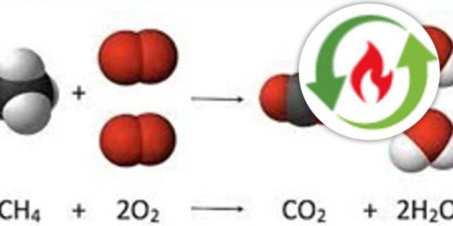
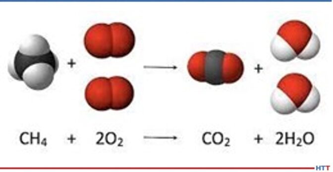
Process heating requires energy input. The energy sources for process heating most frequently include the combustion of carbon-based fossil fuels such as natural gas, propane, fuel oil, diesel, or coal. Also, most combustion processes have a component of electricity to operate combustion air supply blowers, exhaust blowers, circulation fans, conveyors, and other items. Figure 1 shows the chemical process for the combustion of methane (i.e., natural gas).
Figure 1 demonstrates that during combustion, methane (CH4) combines with oxygen (O2) to form carbon dioxide (CO2) and water (H2O). This same process is true for any carbon-based fuel. If you try to imagine all the combustion in progress across the globe at any given time, and knowing that all this combustion is releasing CO2, then it is easy to see the problem and the need for CO2 emission reduction.
Figure 1. Chemical process for methane combustion
(Source: Advanced Energy)
In basic terms, if you have a combustion process on your site, then you are emitting CO2. The electricity consumed to support the combustion processes also has a carbon component and the consumption of this electricity contributes to a site’s carbon footprint. Climate change impacts due to these carbon emissions have prompted government and corporate actions that are creating unique new opportunities for more sustainable and lower carbon process heating methods.
So, combustion and electricity consumption on your site contribute to your carbon footprint. Knowing this, organizations may now want to understand the actual level of their carbon footprint and ways to reduce it. There are many methods and resources available to help organizations understand and work to improve their carbon footprint.
The Industrial Heating Equipment Association (IHEA) has recognized this need to understand carbon footprints and is in the middle of a four-part webinar series on this topic. Session three (held on July 20, 2023) covered methods and resources to help organizations determine and improve their carbon footprint.
Session 3: DOE Tools and Programs for GHG Reduction
There are many options available to help determine carbon emissions for equipment, processes, sites, and organizations. This presentation will review some of these available tools and how to apply them to different situations. Carbon emissions are directly tied to energy consumption, so it is very important to understand how all your energy is consumed on site by energy type. This presentation will provide tools and programs to help you understand your energy consumption and thereby understand your carbon emissions. Additionally, energy improvement projects are also carbon emission reduction projects. This session will help you understand how to determine the impact of energy projects on your carbon footprint.
Session 4: Ongoing Sustainability — Industry Best Practices for Continual Improvement
Carbon reduction is not a project, it is a process, and must be ongoing. Earlier sessions will help you determine your carbon footprint and understand ways to track and improve your carbon footprint. In this presentation, we will review methods and programs to ensure the continual improvement of your carbon reduction efforts. Following the “plan, do, check, act” method used in many continual improvement programs, we will review steps to take for keeping your momentum moving in the right direction. We will also plan to have industry case studies for success in ongoing and improving carbon reduction programs.
Registration for these sessions can be found on the events page of www.ihea.org. If you or your organization want to learn more about your carbon footprint and how to measure and reduce it, you will not want to miss this opportunity.
In summary, heat treating, and other process heating methods, require significant energy, much of which is fueled with carbon-based fossil fuels, and associated with support electricity consumption. Both combustion and electricity consumption contribute to an organization’s carbon footprint. One of the best ways to help manage your carbon footprint is to understand and manage your energy consumption. For more information on this topic, please check out the IHEA Sustainability & Decarbonization Initiatives.
About the author:
Michael Stowe (PE) is the senior energy engineer at Advanced Energy. Michael focuses on process heating and energy efficiency in manufacturing plants. He has significant experience in the manufacturing industry serving in various roles as design engineer, production manager, plant engineer, and facilities engineer over the past 27 years.
Find heat treating products and services when you search on Heat TreatBuyers Guide.com
Scrambling to stay up to date on all the publications that Heat TreatToday's experts have been releasing? If you are attending the ASM Heat Treat show in Detroit today or tomorrow, you can hear them present in live panels on the latest and greatest in the heat treat industry. Learn from the technical expertise of Heat TreatToday'sauthors, interviewees, 40 Under 40 honorees, and other affiliates.
Check out the technical sessions for Tuesday and Wednesday. For a complete list of all technical sessions offered over Tuesday, Wednesday, and Thursday, see ASM's Heat Treat show page.
Tuesday, October 17
Applied Technology / Processes and Applications: Energy Consumption and Efficiency
311 AB, 9-10am
This session features experts Dennis Beauchesne of ECM-USA, Inc. and MadhuChatterjee of AAT Metallurgical Services. Explore topics from adiabatic fluid coolers to the application of artificial intelligence, as well as heat treating emissions and decarbonization strategies. For more details, see here.
Chad Beamer
Applications Engineer
Quintus Technologies
Atmosphere Technology and Surface Engineering I
312 AB, 9-10am
Explore the development of clean HIP processing with Chad Beamer (Quintus Technologies) of Heat TreatToday's40 Under 40 Class of 2023 as well as "Changing Cost Environment Favors Self-Generation of Thermal Process gGases" with David Wolff of Nel Hydrogen. For more details, see here.
"Green” Heat Treating / Low Carbon I
312 AB, 10:30 AM-11:30 AM
Fascinated by the question of how carbon emissions can be reduced during the heat treatment of steel parts? This technical session with Ed Rylicki of Ajax TOCCO is for you! For more details, see here.
Ryan Van Dyke
Applied Technology / Processes and Applications: Quality Control
311AB, 10:30-11:30 AM
Explore the topic of quench cracking during heat treatment with Ryan Van Dyke (Paulo) of the 40 Under 40 Class of 2023 in this technical session chaired by Ben Bernard (Surface Combustion, Inc.). For more details, see here.
Microstructural Development / Characterization II
313 AB, 10:30 AM-11:30 AM
In this technical session, chaired by Dennis Beauchesne, explore topics from nano-crystalline martensitic stainless steel to the pretreatment of steel during carburization. For more details, see here.
New Trends in Global Heat Treating
311 AB, 1:00-1:40pm
Chaired by Angella Sell of Aalberts Surface Technologies (40 Under 40 Class of 2023) and featuring the expertise of Chad Beamer (40 Under 40 Class of 2023), Jianyu Liang (Worcester Polytechnic Institute), Richard D Sisson (Worcester Polytechnic Institute), and Edward Rolinski (Advanced Heat Treat Corp.), this technical session will keep you up to date on global heat treatment, exploring topics as diverse as high pressure heat treatment, plasma nitriding, and boronization. For more details, see here.
Maciej Korecki
Vice President of Business of the Vacuum Furnace Segment
SECO/WARWICK
(Source: SECO/WARWICK)
"Green” Heat Treating / Low Carbon II
312 AB, 1:00 -2:20 PM
Curious for more technical information on "Green" Heat Treating? This follow-up session features Jim Oakes (Super Systems Inc.), Bryan Stern (Gasbarre Products), Don Marteeny (SECO/VACUUM Technologies, LLC), Maciej Korecki (SECO/WARWICK) and Dennis Beauchesne. Topics to be covered include the carbon impact of oil quenching, energy consumption and CO2 footprint, and the environmental impacts of low pressure carburizing. For more details, see here.
Vacuum Processes and Technology
313AB, 1:00 PM-2:20 PM
This technical session features all things vacuum heat treat, with presenters discussing high pressure gas quench, the effect of sintering atmosphere on vacuum sintered stainless steel, the development of CFC-fixtures for industrial heat treat (presented by Jorg Demmel of High Temperature Concept), and the impact of vacuum furnace power on ESG criteria. For more details, see here.
Wednesday, October 18
Simulation & Modeling I: Process Simulation (CFD/FEA)
311 AB, 1:00 PM-2:40 PM
In this technical session, 40 Under 40 honoree Justin Sims (DANTE Solutions, Inc.) will be featured in a discussion of model development for aluminum, while Richard Sisson (Worcester Polytechnic Institute) will discuss phase distributions in heat treat gas atmosphere, and Dr. D Scott Mackenzie (Quaker Houghton) will present on the challenges of visualizing and optimizing the flow inside gear oil quenching tanks. For more details, see here.
Mr. Jason Orosz (Nitrex) of the 40 Under 40 Class of 2020 will be chairing this technical session, featuring 40 Under 40 Class of 2018 honoree Dr.Lesley Frame (University of Connecticut) and Matt Fischer (Castalloy Corp.), presenting on guidelines for alloy trays and fixtures. For more details, see here.
Residual Stress / Panel Session
313 AB, 1:00 PM-3:00 PM
Chaired by Dr. Lesley Frame, a 40 Under 40 honoree, this technical session will explore topics from the relationship between deep case carburizing and residual stress to recent upgrades to the residual stress diffractometer. For more details, see here.
Heat Treating: Induction Heat Treating
313 AB, 3:30 PM-4:50 PM
Fascinated by the topic of induction heat treating, including improvements on performance and induction fatigue following carburizing? Be sure to attend this technical session featuring David Lynch (Induction Tooling, Inc.), Justin Sims, and RichardSisson. For more details, see here.
Industry Internet of Things
312 AB, 3:30 PM-4:50 PM
This technical session explores the topics of AI, furnace smart data, and predictive maintenance, all in relation to the heat treating industry. Featuring experts Trisha Rouse (General Motors), Peter Sherwin (Eurotherm LLC), and Aymeric Goldsteinas (Ipsen USA), discover information on these pertinent questions. For more details, see here.
D. Scott MacKenzie, Ph.D
Senior Research -- Metallurgy
Quaker Houghton, Inc.
Quenching Technologies I: High Pressure
311 AB, 3:30 PM-4:50 PM
This final technical session for Wednesday features a discussion of quenching technologies, with topics ranging from nitrogen gas quench to induction hardened cylinders. Finish off your Wednesday with experts Dennis Beauschesne, Chad Beamer, Tom Hart (SECO/VACUUM), and D Scott McKenzie. For more details, see here.
Find heat treating products and services when you search on Heat Treat Buyers Guide.com
Today is a little-known holiday: National Veterans BBQ day, on which Americans are encouraged to treat veterans to a cookout as a “thank-you” for their service.
At Heat Treat Today’s, we wanted to take this opportunity to recognize veterans who have donned the hat of heat treating, although we can’t offer a physical celebration. Thank you for your service and sacrifice for our country.
Below, you will find profiles of Heat Treat Veterans from our archive. Heat Treat Today is continually updating our records of individuals in the heat treat industry who have served/are serving in the U.S. military. If you are or know a military veteran whom we can add to this living archive, please reach out via the online form or email Bethany Leone, managing editor, at bethany@heattreattoday.com.
This article as originally published in Heat Treat Today’sSeptember 2023People of Heat Treatmagazine.
Larry Bradley
Bradley has been in the heat treat industry for two years and works as quality manager at Bodycote. Military Branch: Army Active Service: January 1972 to December 1979 Highest Rank Achieved: E-6 Staff Sergeant Service Details:
• Vietnam War • Basic — Fort Knox • AIT — Fort Benning • Airborne School — Fort Bragg • Aberdeen Proving Ground in Maryland (Introduction to Quality) • Bronze Star, Silver Star, Purple Heart, Army Commendation Medal • Also stationed at Kaiserslautern Germany, and 100th Division Echo Company at Morehead, KY • Mobilized for Operation Enduring Freedom and stationed at Camp Atterbury, IN
Bradley Johnson
Johnson has been in the heat treat industry for 8 years and works as quality engineer at Bodycote. Military Branch: Army Active Service: October 2000 to August 2007 Highest Rank Achieved: E-5 Sergeant Service Details:
• Involved with Operation Enduring Freedom • Basic Training at Fort Leonard Wood, MO • AIT at Fort Lee VA • First duty Station at 400th QM • Also stationed at Kaiserslautern Germany, and 100th Division Echo Company at Morehead, KY • Mobilized for Operation Enduring Freedom and stationed at Camp Atterbury, IN
“As far as stories, I tend to not delve too deep into my tenure as a serviceman, but what I will share is: There are very few people in the United States that truly understand what it means to sign a blank check of your life, being willing to risk it for the county that you love, as well as the millions and millions of its citizens, at the drop of a hat, if called to action. With regards to basic training, I as well as numerous others I am sure, believe that the experience was the most fun and exciting adventure that I would never do again. I was in AIT when the 9/11 attacks happened, and on that day, we all knew we were going to war. It was just a couple short years later when I was mobilized for OEF. I was attached to the 658th out of Mississippi, and we traveled to Camp Atterbury, IN, for our pre-deployment training. We were there for around 3–4 months, chomping at the bit, to go do our part in protecting our country and for a lack of better terms, enact revenge for the ones we tragically lost that fateful day in September 2001. We were three days away from boarding the plane and heading overseas when we got word from the Pentagon that our particular mission was cancelled, and they were sending us home. Come to find out, we were going to be sent to the southeastern part of Turkey, to be able to invade Iraq at its northwestern border. When Turkey denied our access, that was the ticket home. After getting back home I submitted a transfer request to be able to join the 100th Division. It took about a month, but the transfer went through, and I was now a part of a drill sergeant unit (Echo Company) and was making trips to Ft. Knox to push troops through their basic combat training. To be able to come full circle in that regard was one of the most rewarding adventures I have ever had. To clarify, I was not a drill sergeant myself, merely cadre, but I was an NCO, and just by having that rank, the fear in the recruits’ eyes when you walked into the room took me back to being in their shoes. And this is where I ended my career.”
Jon Tirpak
Tirpak has been in the heat treat industry for 42 years. Branch of Service: United States Air Force Active Service: 1982 to 1988 Highest Rank Achieved: Captain Service Details: Captain, United States Air Force, Norton Air Force Base, CA, 1986 to 1988.
Led an $18M Air Force-wide, integrated effort to evaluate materials and structures in underground nuclear tests and managed Small Business Innovative Research Projects.
Lieutenant, United States Air Force, Wright Patterson Air Force Base, OH, 1982 to 1986.
Served as an Executive Officer within Project Forecast II (an Air Force “think tank”) and focused expertise on advanced materials and manufacturing in Plans and Programs.
Office of the Air Force Materials Laboratory — conducted structural failure analyses; characterized effects of plastic bead paint removal. Centrifuge test subject with 43 tests, some approaching 8.5 Gs. Designed and conducted data generation programs to characterize the fatigue and fracture of cast aluminum and generated static and dynamic property data for various metallic alloys.
“My military career took off in 1982. Earning a Bachelor of Science degree in Metallurgical Engineering at Lafayette College and completing four years of Air Force ROTC Training, the best assignment for me was the Air Force Materials Laboratory at Wright Patterson Air Force Base. Those formative years linked me to heat treating, for most alloys without thermal processing are just metallic chemistries! For example, a popular alloy then was A357 comprised primarily of aluminum, silicon, and magnesium. To impart useful properties after casting, heat treating is required, and in the case of A357 industry specified -T6. We can’t have one without the other; we need alloy suppliers and metal workers (foundries, forges, etc.) AND heat treaters. We don’t need a lot of them; we need just the best, world class producers with the passion, people, processes, and purpose for serving humanity. Back in ‘82, my take off for success was via the Air Force and cast aluminum alloy A357 with a heat treat “afterburner” of -T6. In 2023, I have yet to land!”
Awards: • United States Air Force Commendation Medal • United States Air Force Achievement Medal with two Oak Leaf Clusters • United States Air Force Outstanding Unit Military Ribbon • United States Air Force Service Longevity Ribbon • United States Air Force Training Military Ribbon • United States Air Force Centrifuge High G Test Subject Certificate • Lifetime Member Air Force Materials & Manufacturing Alumni Association, Dayton, OH
Danny Woodring
Woodring has been in the heat treat industry for 28 years and works as manager of the Quality/ISO & Flow Team at UPC-Marathon. Branch of Service: Army Secondary Branch: Army National Guard Active Service: 1982 to 1996 U.S. Reserves: 1996 to 2022 Highest Rank Achieved: Sergeant Major/E9 Service Details: • Participated in three Combat Tours
Timothy Wright
Wright has been in the heat treat industry for 30+ years. He was founding owner of WIRCO. Branch of Service: Army Secondary Branch: Army National Guard Active Service: Yes U.S. Reserves: Yes Highest Rank Achieved: Major General Service Details: • Vietnam War • Desert Storm • United Nation’s SFOR in Bosnia-Herzegovina • Indiana National Guard • Silver Star, Legion of Merit, Bronze Star, Meritorious Service Medal x8, Air Medal x27 (1 for Valor), Army Commendation Medal x5 (1 for Valor), Kuwait Liberation Medal, and more.
Heat Treat Today interviewed MG Wright and will be releasing the full story of his extraordinary service and sacrifice on Heat Treat Radio in fall 2023. Watch for it at www.heattreattoday.com/radio.
Find heat treating products and services when you search on Heat Treat Buyers Guide.com
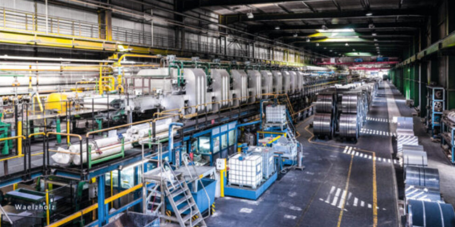
A long-term test of high-efficiency and ultra-low-emission burner technology from WS Wärmeprozesstechnik at Waelzholz demonstrated that hydrogen can be used as a fuel gas to heat silicon strip lines.
Energy-efficient and low-emission heating of silicon strip lines using hydrogen as a fuel was the focus of an extensive test C.D. Wälzholz GmbH & Co. KG successfully completed together with WS Wärmeprozesstechnik in 2022.
As early as summer 2021, WS delivered several patented FLOX® burners for the installation in an existing silicon strip line. This line uses SiSiC radiant tubes to heat the furnace to a temperature of approximately 1922°F. After commissioning, the WS burners successfully operated with 100% hydrogen for one year.
The long-term test showed that a switch to hydrogen as a fuel is very possible for the furnace under investigation. Commenting on the possibility of such a switch, Mr. Peter Höfinghoff, expert for thermal process engineering in the technical office at Waelzholz, concluded: “Even after a year of operation, the burners are running very well and without faults. We were able to sufficiently demonstrate that by using WS burners, a conversion to hydrogen is technically feasible without any problems.”
With the findings from the test operation, the company is laying a foundation stone for the future hydrogen strategy at its headquarters in Hagen.
Find heat treating products and services when you search on Heat Treat Buyers Guide.com
Renewable fuels or hydrogen have entered the scene as these are fuels that contain little or no carbon. So, no carbon in the fuel means no CO2! These fuels present an excellent opportunity to significantly reduce carbon.
This Sustainability Insight article was composed by Brian Kelly, manager of Application Engineering at Honeywell Smart Energy and Thermal Solutions (SETS) and president of the Industrial Heating Equipment Association. It can be found in Heat Treat Today's August 2023 Automotive Heat Treatingprint edition.
The need to understand the impact of greenhouse gases (GHGs), especially carbon-based emissions, on climate change is gaining much more interest recently from organizations that have industrial heating processes. Most industrial heating processes are fueled by carbon-based fossil fuels such as natural gas, propane, fuel oil, diesel, or coal. In basic terms, if you have combustion processes in your organization, you are emitting carbon (CO2). Impacts on climate change due to these carbon emissions have prompted government and corporate actions to reduce carbon. These actions are creating unique new opportunities for more sustainable and lower carbon process heating methods. In this article, we will focus on ways to reduce carbon in typical fossil fuel fired heat treat thermal processes. First step: Figure out where you are today. Do you know?
Assess Your Carbon Footprint
Brian Kelly
Image Source: Honeywell
More and more companies are interested in understanding their GHG/carbon footprints, so they can determine what processes are their biggest CO2 offenders, and on what assets to focus on in order to have the largest impact on reducing carbon. Whether your thermal processes are being heated by fossil fuels (typically natural gas) or electrically, each will have a carbon footprint. Fuel gases are being burned to provide the heat and they produce CO2 as a result. Most electrical power is currently being produced by fossil fuels, so electricity will have a CO2 amount associated per kW. What can be done to burn less fuel in your furnaces or ovens, which directly relates to reducing CO2?
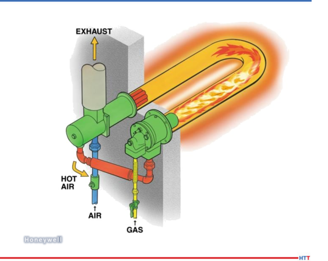
Tune Your Combustion Systems
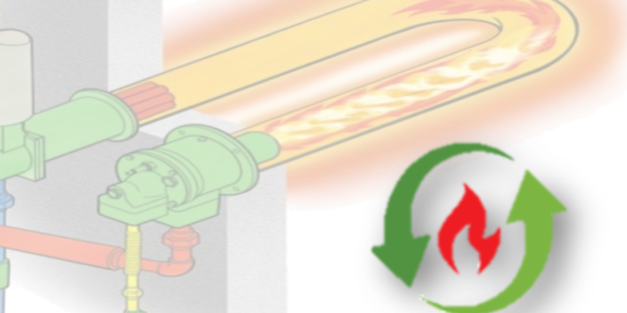
Radiant tube burner with plug recuperator in a U-tube
Source: Honeywell
Over time combustion systems drift and are not at their optimum air/fuel ratio. By simply tuning your burner system on a routine basis, you can fire at the optimum air/fuel ratio for the process and be as efficient as possible. For example, if a furnace is firing on natural gas, operating at 1800°F, and currently operating at 35% excess air, tuning your burners to 10% excess air could save approximately 15% in fuel consumed. The fuel costs will be reduced, and the resulting CO2 will be reduced by that same percentage!
Maintain Your Furnaces/Ovens
A simple review of your furnaces or ovens to observe any hot spots, openings, faulty seals, or refractory issues will identify areas that will cause your systems to operate less efficiently, thus using more energy. Repairing these problems and consistently maintaining them will have the systems running more efficiently and producing as little carbon as possible.
Upgrade Your Firing Systems To Be More Efficient
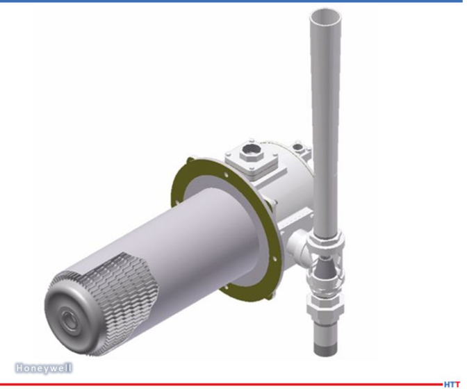
Direct fired self-recuperative burner
Source: Honeywell
Incorporating preheated combustion air into furnace combustion systems can significantly reduce fuel consumption and therefore the resulting carbon. The two main methods for introducing hot air into a combustion system are recuperation and regeneration. The most popular air preheating method in heat treating applications is recuperation. For a direct fired furnace, this can take the form of a central stack recuperator or self-recuperative burners. Self-recuperative burners have grown in popularity in recent years as they get rid of the need for hot air piping, recuperator maintenance, and most are often pulse fired, which will not only maximize efficiency but also promote temperature uniformity in the furnace and often be lower in emissions. For indirect fired (radiant tube) furnaces, you can apply/add a plug recuperator to an existing cold air fired burner in a furnace that has a U or W-tube to preheat the combustion air or apply self- recuperative burners installed in Single-Ended Radiant (SER) tubes to optimize your furnace firing. The SER tube material can be upgraded to silicon carbide which allows higher temperatures/flux rates that can provide the opportunity to increase throughput and reduce the possible CO2 per cycle.
Combustion air preheating can result in energy savings of close to 25% over cold air combustion.
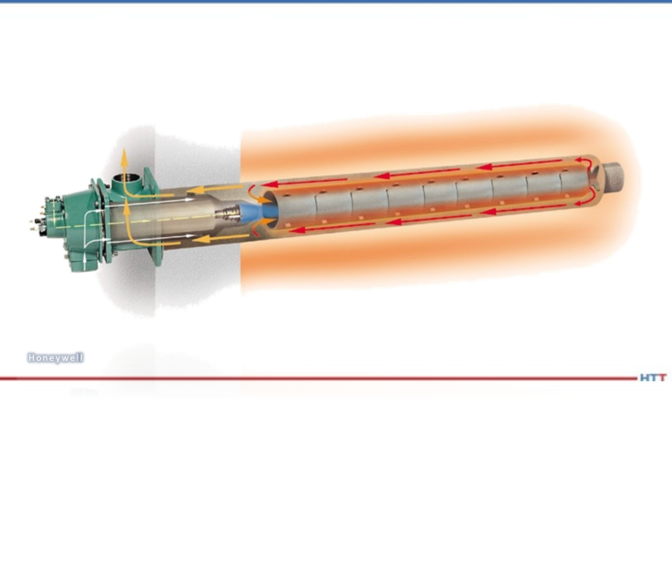
Renewable Fuels/Hydrogen
Renewable fuels or hydrogen have entered the scene as these are fuels that contain little or no carbon. So, no carbon in the fuel means no CO2! These fuels present an excellent opportunity to significantly reduce carbon. Hydrogen has been of interest because it has the opportunity to be a zero-carbon industrial fuel when produced with renewable energy such as wind, solar, hydro, or nuclear power. As these methods become more prevalent, they bring down the price of hydrogen and increase its availability. This could be a significant driver to greatly reduce CO2 in thermal processes. These topics as well as many others are being discussed in an on-going Sustainability Webinar series hosted by IHEA to provide education and insight into the ever-changing sustainability landscape.
Single ended self-recuperative radiant tube burner
Source: Honeywell
About the author:
Brian Kelly is manager of Application Engineering for Honeywell Smart Energy and Thermal Solutions (SETS) and current president of the Industrial Heating Equipment Association (IHEA).
Find heat treating products and services when you search on Heat TreatBuyers Guide.com
The primary advantage of pre-mix burners is the reduction of comparative emissions. But converting a nozzle mix to a pre-mix burner involves more than a burner exchange. There are many factors to consider when designing any combustion system. This article is a brief outline of the functioning technology for two common low-temperature (below 1200°F) combustion systems.
This Technical Tuesday article was composed by Robert Sanderson (PE), Director of Business Development, Rockford Combustion for Heat TreatToday'sAugust 2023 Automotive Heat Treating print edition.
What Is Low Temperature?
Contact us with your Reader Feedback!Robert Sanderson P.E.
Director of Business Development
Rockford Combustion Solutions
(Source: Rockford Combustion Solutions)
“Low temperature” is a nebulous term. What may be considered high temperature to one user may be regarded as low temperature by another. For this review, low temperature is any heating process where the firing chamber conditions are below auto-ignition temperature of the fuel — which, for many hydrocarbons and other combustible fuels, is about 1200°F — and sufficiently low that the chamber construction could be a metal-lined interior with external insulation.
Low-temperature applications vary, but they are commonly used to heat larger volumes of process air directly. As such, the burner’s air consumption is not a factor in the overall process efficiency.
Technology In Focus: Nozzle Mix vs. Pre-Mix Burners
Nozzle mix burners come in a great variety of designs. Some are simple gas spuds, others are linear arrays of fuel jets. A step up from these basic designs are machined fuel nozzles made to blend air and fuel. Some nozzle mix burners rely upon process fans to supply combustion air while others incorporate combustion blowers.
Regardless of the specific burner configuration, low-temperature burners are often capable of large temperature lifts, high heat-flux inputs, and wide operating ranges.
The control systems for nozzle mix burners are traditional fuel and air designs that many users will be familiar with. These burners are typically capable of operating on various fuels with relatively low utility pressures.
Pre-mix burners are also available in both point and line heat release designs. Pre-mix burners commonly feature low emissions, often the driving factor for their selection. To manage emissions, the general operating characteristics of pre-mix burners often include soft heat-flux inputs, narrow operating ranges, advanced fuel/air control systems, singular fuel designs, and elevated utility pressures.
These features vary somewhat with each design, but all are aspects commonly used as emissions control mechanisms. The control of pre-mix systems is more complex, and it is common for end-users to have training to understand better the proper operation and maintenance required to uphold their safe performance.
A notable difference between nozzle and pre-mix burners is the fuel/air blending design.
Many nozzle mix designs combine the fuel and air within a fuel nozzle directly at the point of combustion. The mixing of these streams may be staged or partially blended, depending on the nozzle design. Pre-mix burners, in contrast, typically have aggressive blending zones to thoroughly aerate the fuel, producing a homogenous, combustible mixture. This mixture is then distributed to the burner’s combustion zone. For safety, integrated with pre-mix burners will be a flashback arrestor or a similar fuel safety design feature.
Behind each nozzle and pre-mix burner system are fuel and air control systems. Because the two burner categories differ, each fuel control system style is unique and designed for that burner’s operating parameters.
The System at Large
An appropriately designed combustion system will consider the process conditions, user needs, and burner parameters in the design of the fuel and air control systems. If any aspect is lacking, the result can be an underperforming combustion system.
About the author:
Robert (Bob) Sanderson has years of experience knowledge and is experienced in a variety of industries. Throughout Bob’s 32+ years of experience experience in the combustion field, he has worked in automotive, abatement-oxidation, aerospace, agriculture, food and beverage, HVAC, heat treating, glass, asphalt, pyrolysis, reducing furnaces, dryers, immersion heaters, and power generation. Bob has been employed by companies such as Eclipse, Honeywell, and Haden, Inc. Bob brings systems integration and the application experience of how systems interact in various environments to his current role at Rockford Combustion. Bob is a member of the NFPA-86 technical committee.
Find heat treating products and services when you search on Heat Treat Buyers Guide.com
Earl Good Managing Director at Retech Systems, LLC Source: Retech
Spark plasma sintering technology innovator, GeniCore, will be expanding their North American influence in the powder metal processes market through a partnership with a New York-based metallurgical equipment manufacturer.
GeniCore has established cooperation with Retech Systems, LLC, a SECO/WARWICK Group division, to expand offerings in powder metal processes with spark plasma sintering. “Cooperation with Retech gives us the honor to serve discerning and distinguished customers in the North American market,” commented Marcin Rosiński, CEO at GeniCore.
The spark plasma sintering (SPS) process bonds materials using a combination of pressure and thermal energy applied to materials in a mold. It resembles hot pressing, but the SPS process consumes far less energy and can bond a broader range of materials into novel composites unachievable by other processes.
“[Bringing] SPS into our repertoire and representing its capabilities is a win for Retech, GeniCore, and our customers,” said Earl Good, managing director and president at Retech.
No better time to turn up the heat than Valentine’s Day! Of course, we at Heat TreatToday are talking about the heat treatment kind of heat!
Looking into history, the work of blacksmithing was one of necessity for every day life. Tools for man and horseshoes for the workhorses were some of the things required from the smithy’s forge. Take a step back in time to read this poem by Henry Wadsworth Longfellow about the way things used to be.
The Village Blacksmith
Under a spreading chestnut-tree
The village smithy stands;
The smith, a mighty man is he,
With large and sinewy hands,
And the muscles of his brawny arms
Are strong as iron bands.
His hair is crisp, and black, and long;
His face is like the tan;
His brow is wet with honest sweat,
He earns whate’er he can,
And looks the whole world in the face,
For he owes not any man.
Week in, week out, from morn till night,
You can hear his bellows blow;
You can hear him swing his heavy sledge,
With measured beat and slow,
Like a sexton ringing the village bell,
When the evening sun is low.
And children coming home from school
Look in at the open door;
They love to see the flaming forge,
And hear the bellows roar,
And catch the burning sparks that fly
Like chaff from a threshing-floor.
He goes on Sunday to the church,
And sits among his boys;
He hears the parson pray and preach,
He hears his daughter’s voice
Singing in the village choir,
And it makes his heart rejoice.
It sounds to him like her mother’s voice
Singing in Paradise!
He needs must think of her once more,
How in the grave she lies;
And with his hard, rough hand he wipes
A tear out of his eyes.
Toiling,—rejoicing,—sorrowing,
Onward through life he goes;
Each morning sees some task begin,
Each evening sees it close;
Something attempted, something done,
Has earned a night’s repose.
Thanks, thanks to thee, my worthy friend,
For the lesson thou hast taught!
Thus at the flaming forge of life
Our fortunes must be wrought;
Thus on its sounding anvil shaped
Each burning deed and thought.
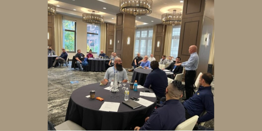
The Metal Treating Institute (MTI) hosted a special meeting for members at the Embassy Suites by Hilton in Downtown Pittsburgh, PA, on Monday, October 17, to review key Nadcap and AMEC topics. During the meeting, members addressed challenges that heat treaters face in Nadcap/audit compliance, how to navigate audits more effectively, and what suggestions to present to the Nadcap committee so that heat treaters would be better equipped for audits.
MTI’s Technical Standards Committee Co-Chairs Bob Ferry, VP of Engineering and Quality at FPM Heat Treat, and Edward (Ed) Engelhard, VP of Corporate Quality at Solar Atmospheres, facilitated the meeting. It was hosted by Tom Morrison, CEO MTI Management, and Jim Orr, president of Penna Flame Industries and current president of MTI. Several attendees who made particularly significant contributions to the discussion were; Doug Shuler, lead auditor at Pyro Consulting, LLC; and Roy Adkins, director of Corporate Quality at Braddock Metallurgical and recipient of the 2022 MTI Award of Industry Merit.
A Room Full of MTI members Including (l-r): Doug Glenn, Ed Engelhard, Bob Ferry, and Doug Shuler
At the meeting, attendees identified the number one challenge in Nadcap/audit compliance is understanding and implementing new Nadcap revisions; a close second was the challenge of ensuring quality when auditors give different feedback. These challenges were addressed in the meeting, especially when discussing two specific topics: first, Auditee Advisories – Type P (Potential Product Impact) and Type C (Confirmed Product Impact) as well as Audit Observations.
Several key points that came out of these discussions were to (1) always read up on the most recent revisions in order to be confident in your compliance with quality standards; (2) be sure to reference objective evidence on the Nadcap Checklist questions to help facilitate the audit; (3) let the Nadcap auditor do their job but address any clarifications/follow-ups to the staff engineer immediately; (4) investigate immediately when receiving a Type P write-up so that you can ask the auditor to add a comment on the limits of that product impact; and finally (5) always push-back on findings that are clearly not valid so that they are “voided” by the Performance Review Institute (PRI).
Another main point of the meeting was to address AMS2750H, an update consisting of editorial and language updates for added clarity.
Lastly, the facilitators of the meeting addressed aerospace standard AS13100: AESQ Quality Management System Requirements for Aero Engine Design and Production Organizations. The standard seeks to harmonize and simplify supplier quality requirements among the major aero engine manufacturers, supplemental to standard AS9100. This standard is in the process of being flowed down to the supply chain and compliance is required January 1 of 2023, meaning that heat treaters have a couple months to get up to standard.
This special meeting happens each year during the October Nadcap meeting in Pittsburgh, PA. MTI encourages heat treaters to attend the Nadcap meetings to share their invaluable voice to guide industry standards.
Photo caption for main image: Jim Orr speaks to members of MTI.
Find heat treating products and services when you search on Heat Treat Buyers Guide.com
Today's episode delves into the term "austempering". What is it? Why do heat treaters need to use it? For what applications is it necessary? Join Doug Glenn, publisher of Heat Treat Today and host of this podcast, as he talks with "The Heat Treat Doctor", Dan Herring, about all things austempering.
Below, you can watch the video, listen to the podcast by clicking on the audio play button, or read an edited transcript.
The following transcript has been edited for your reading enjoyment.
Earlier Episode of Lunch & Learn
Doug Glenn (DG): Alright, welcome everyone. We’re here with another Lunch & Learn with Dan Herring. Today, we’re going to be talking about the principles of austempering. We do these Lunch & Learns really for the benefit of our Heat TreatToday team and we knew that learning from Dan would also be educational for the entire industry. We are just really happy to be able to have Dan Herring with us once again to educate us a bit. We’re going to try to spend about 30 minutes or so learning about some of the very basic principles of austempering. So, the ball is over the fence to you, Dan.
Dan Herring (DH): Well, welcome everyone. It’s my pleasure to discuss the heat treat topic that we call austempering. One of the things we’re going to do today is we’re going to recall from a previous Lunch & Learn the definition of heat treating. We called it the controlled application of time, temperature, and atmosphere to produce a predictable change in the internal structure of what metallurgists call the microstructure of a material. So, we’re going to introduce various words that are related to different types of microstructures today or these internal structures.
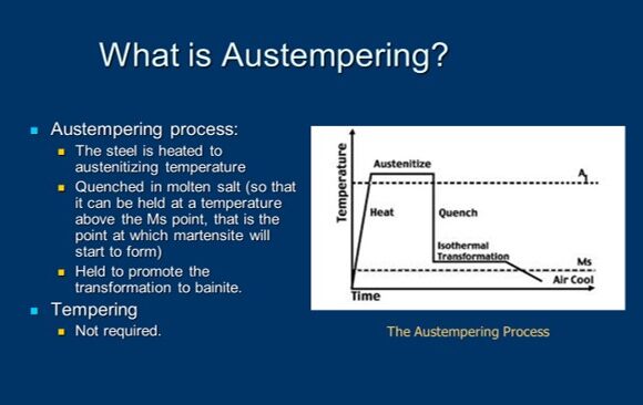
But before we do, I’ve put on the screen a brief definition of austempering. It’s certainly a heat treat process. It’s used in medium to high carbon, both plain and alloy steels, as well as cast irons (an example being ductile iron) and we’re trying to produce a microstructure called bainite which is probably a foreign word to most of you and I’ll endeavor to explain it in a moment.
But to give you just a view from about 30,000-feet, you might be asking yourself, “Well, what types of products are austempered and why?” So, I put a couple of examples here. I’ve put an example of a lawnmower blade, seat belt components like the tongue and receptacle, and some tractor parts, as well.
A good example of this might be the seatbelt components. We’ve learned to put on seatbelts (in my day, we didn’t have them, but now we do) and we all learned to buckle up. And, if you get into an accident, you discover why your seatbelt is really your friend. We want something that’s strong, that if we get into an accident, it will not shatter and break. But, at the same time, we want something that’s tough and slightly ductile so it will bend and not break.
Austempering is a process that’s used to produce all seatbelt components, that I’m aware of. Similarly, with lawnmower blades- we don’t want a blade, if it hits a rock as we’re mowing the lawn, (I don’t expect most of the people on the call to have mowed the lawn), but if we hit a rock or a hard object as we’re mowing the lawn, we might want that lawnmower blade to get a ding in it, but we don’t want it to shatter. So, those are some typical examples.
You might ask yourself, why do you austemper? What we’re seeing here is that if you need increased ductility, toughness, and strength at a given hardness level, austempering is right for you. We’re typically talking about parts that are in the range of, maybe, 35-55 Rockwell C. We are developing, as I said, a bainitic structure as opposed to a martensitic structure, which is what’s produced when we harden a steel and quench into something like oil or water.
So, we get improved toughness. And we get some superior properties related to that, as well. And some of the properties don’t change very much but they’re equal to what we get when we harden the steel, when we get this martensitic structure.
The bottom line is we typically get less distortion, we get better wear resistance, we don’t suffer from cracking as some of the high carbon steels are prone to do, and, interestingly enough, with cast irons, we get some, what are called "improved dampening characteristics" -- noise and vibration. So, wire is an important like, for example, in an automotive engine to have dampening characteristics because we want the engine to run quietly.
What types of materials can be austempered? This is just a partial list, but mostly it’s medium carbon steels. That’s carbon steels with anywhere from .5 carbon to .95 carbon or, in other words, an AISI 1050 to 1095 grade. We can also do medium alloy steels -- the 4130’s, the 4140’s, the 5140’s, the 5160’s, etc. Certain stainless steels can be austempered although not many of them. And, as I said, cast irons, the example being ductile iron, can also be austempered.
And I wanted to give you some idea of the mechanical and different properties of steel. We talked in an earlier Lunch & Learn about the fact that steel is an alloy of iron and carbon and manganese. And we add other elements to the mix in order to get various either mechanical properties, chemical properties, electrical or magnetic properties, and certain other advantages.
So, an example of mechanical properties that we’re typically interested in is hardness and strength, brittleness, ductility, elongation, wear, and shock resistance. Now, strength is measured a number of ways. There are things called "fatigue strength" and "flexure" and "impact strength" and "sheer strength" and "tensile strength" and "torsion strength" and "yield strength."
This is a metallurgist’s rendition of a teeter totter in a schoolyard. Now, don’t laugh. This is what defines the difference between a metallurgist and a mechanical engineer. For all the mechanical engineers out there, metallurgists draw cartoons -- that’s the easiest way to say it. Howsoever, at one point in all of our lives, we’ve probably been on a teeter totter. We know that, in this particular teeter totter, we have strength properties on one side of the teeter totter and ductility properties on the other. We know that as the strength goes up, the ductility will go down and as the ductility will go up, the strength will go down. As a result of this, we decide what we want for properties and we realize that there’s a compromise going on. If we make them extremely strong, they’ll be brittle because they’ll have very, very low ductility. If we make them extremely ductile, they’ll have very low strength. So, this balancing act is what we’re trying to do when we look at the properties we’re trying to achieve. And, if you remember, the microstructure is what gives us these properties.
Now, this is something that is not intended to confuse, but I thought I’d add a little metallurgy into the mix because we are going to talk about several microstructures. This is what metallurgists call a "time temperature transformation" or "TTT diagram." This is really an artist’s rendition of one. There is a lot more information typically contained in one of these diagrams. But for our purposes, it isn’t too important. We can use this artist’s rendition to get the essence of what we’re trying to do.
We start off by heating steel to austenitizing temperature. And that’s above the dotted line shown in this particular diagram, so, at the very top of those turquoise lines and temperature. And then what we do is we make sure that the component part is uniformly up to temperature and now we get ready to harden it. We get ready to quench it. What we’re dealing with is we’re rapidly cooling, and under normal hardening, you’ll notice that there are two lines there- one called MS and one called MF. MS is the martensite start line and MF is the martensite finish line.
Typically, in hardening, our goal is to produce martensite. In order to do so, we want to cool rapidly enough to miss what we call "the nose of the curve" because if you look at this type of diagram, you’ll see that it, on profile, looks like somebody’s nose and the turquoise lines are missing the "nose" of the curve. As a result of that, we’re cooling rapidly. But the difference between hardening and austempering is that we don’t cross the MS point, we don’t cross into the martensite range. We don’t transform to martensite, instead what we do is we put the brakes on, we stop, and then we introduce a long soak or hold period and we cross into the banitic range of the curve.
And, so, austempering is typically performed about 25-50 degrees Fahrenheit above the martensite start temperature of steel. Now, there are some exceptions, but that’s a very typical range. If we’re not controlling the process properly, we might get a microstructure that’s both bainite and martensite. But if we do our job right, we’ll get a fully bainitic structure, which is often what we desire.
Read More in Dan Herring's Books
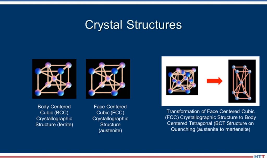
Now (and I realize this has words that some people may be unfamiliar with) but we’ve heated the part up until we’re austenitic- we’re in the austenite range, and there are three various methods of cooling that can be employed. On the far righthand side, if we rapidly quench a part into oil or into water, we might produce a microstructure that’s called martensite. It’s a body-centered tetragonal microstructure. We get something that’s very hard, but brittle. That’s why we have to reheat it and perform a process called ‘tempering’ in order to take some of the brittleness away and add some ductility back in.
Now, on the far lefthand side, we may slow cool the part rather than rapidly quench it and we produce a microstructure that is both ferrite and pearlite, the result of slow cooling. So, instead of getting something that’s very hard, we get something that is very soft. You might say, “My gosh, why do we want to do that?” Well, we like to do that sometimes because we like to take a steel and, for example, machine it into a final form before we go back in and reharden it. So, as a result of that, we form a ferrite/pearlite microstructure, we’re able to machine the part, then we can go back in and reharden it.
So, slow cooling gives us a ferrite/pearlite microstructure, rapid quenching gives us a martensitic microstructure, and a moderate cooling rate (the one shown in the center) gives us a bainitic microstructure. Bainite is a mixture of ferrite and cementite. Again, words that you’re perhaps not familiar with. But the way I like to say it is martensite gives us a microstructure that is not as hard as martensite but tougher, in general, than martensite, and we’ll explain that as we move forward.
But I thought before we do, you might want to see some typical type of heat-treating equipment that is used to austemper parts. A lot of parts are done in a mesh belt conveyer line. The one that is shown on the left, where parts are loaded onto a table, sent through the furnace, and dropped at the end of the furnace into a salt quench which is located in the floor, in this particular drawing. Salt is the primary medium that we quench parts that will be austempered in because salt gives us the temperature-range we need to be above the martensite start point.
Now, a number of people have asked me in the past: Can I use oil rather than molten salt to perform this operation? There are certain oils that can be used at extremely high temperature, but there are fire hazards and other hazards associated with them so the typical answer is ‘no’; molten salt is typically used to perform the quenching.
So, you have a mesh belt conveyer system for high volume, shown on the left. On the right, you’re showing a typical Shaker Hearth furnace where what happens is you load parts onto a pan that vibrates and the parts are moved down the length of the furnace and then drop into a salt quench at the back end.
I thought you might want to see some pictures of some stampings and things that are going into one of these mesh belt conveyer furnaces. You see the endothermic gas in this particular picture burning out the front of the furnace and the stampings moving on a conveyor belt, a mesh belt, in through the furnace. All sorts of different types, shapes, and sizes of stampings. One thing you’ll notice is that these parts are, typically, not single layer loaded; they’re loaded, perhaps, one to three to five parts thick, somewhere between anywhere from a half inch to about two or three inches thick as they’re moving through this conveyor belt.
And to complete the metallurgy aspect of it, you might say, “Hey, what type of microstructure am I actually seeing?” The picture on the left is a primarily bainitic microstructure with some martensite and its hardness is 44 Rockwell C. The microstructure on the righthand side is a combination of bainite and ferrite. The ferrite in this microstructure shows up as white or very light in color, exactly. This hardness, because you have ferrite present, is about 36 HRC. So, depending on the hardness you’re trying to achieve, you will get different types of microstructures- that’s the purpose of this slide.
Now, as far as molten salt goes, a typical austempering bath consists of either a sodium nitrate or a potassium nitrate salt, typically in a 50/50 mixture, and this salt is operating somewhere between 300 degrees Fahrenheit and 650 degrees Fahrenheit, depending on, again, the desired, not only the composition in the salt, but the desired temperature that we would want to hold to.
Let me back up for a second, Doug. So, to kind of summarize this: What we’re trying to put the brakes on as we’re rapidly cooling down, missing the nose of the transformation curve, we want to fall into this bainitic region and, in order to do so, we need to stay above that martensite start temperature which for many steels is in the 400–450-degree Fahrenheit range. So, our molten salts will typically run at 475, 500, even 550 degrees, all the way up to 650 degrees. So, we pick our salt temperature, not only depending on the salt, but also depending on the temperature that we want to hold the bath in.
Some of the reasons for selecting a salt quench are that the temperature of the salt bath dictates the ultimate hardness that we’re going to achieve. You might find this interesting: If I didn’t mention it in a previous Lunch & Learn, but I did, it’s that when we quench into the martensite range or field, martensite is the instantaneous sheer transformation. It really progresses at the speed of sound. So, martensite forms almost instantaneously, but bainite requires time for the transformation to take place.
So, a typical time in the salt is somewhere in the range of 18-20 minutes. I’ve seen parts held in salt for as short as 10 or 12 minutes and for as long as 30 minutes, but it depends on the thickness of the part, the material and, ultimately, the desired hardness we are going to reach. Now, interestingly enough, as opposed to a part that we harden to martensite and have to retemper or temper to balance the teeter totter, so to speak, with an austempering process, we do not need to temper afterwork because the parts are effectively tempered, so to speak, in the salt. So, we have a hardening operation that results in a banitic structure but we don’t need to temper. So, that’s one of the differences between hardening and austempering.
Again, the time in the salt will decrease as the transformation temperature increases and the time in the salt is similarly associated with the carbon content in the steel.
Let me give you a couple of examples: I mentioned in an earlier slide that SAE 1050, 1055, 1075 steel are typical steels that are austempered. Again, your austempering goes to put the hardness typically in the range of 40-45 Rockwell C, not nearly as hard as if we harden and quench them into oil or water, but certainly hard enough to give you a properly austempered part, giving you this part that is a combination of good hardness and yet a lot of ductility.
This, in a nutshell, is a brief summary of austempering. We’ve kind of said what it is -- it’s a process that’s going to get us a bainitic microstructure. We’ve looked at a little of the metallurgy of what we’re dealing with here and we’ve seen that it’s a different type of microstructure than is something like annealing or normalizing which gives you a primarily ferritic and pearlitic microstructure. And it’s different than hardening that gives you primarily a martensitic or tempered martensitic structure.
So, for those parts that require not only hardness but toughness, austempering is a process that should be considered by heat treaters.
Doug, that’s really the end of the presentation that I’ve prepared. We can certainly discuss it a little bit more if anyone has any questions.
DG: At the beginning, you were talking about pearlite and all that stuff, did we talk about austenite?
DH: Well, we talked about austenite because, again, that’s the temperature to which we heat the parts up to at the very beginning. In other words, to start the process, we heat the parts up to the austenite field, if you will. In other words, the parts are essentially red hot. They are above the proper transformation point that they turn into austenite.
DG: So, I assume that’s here, if you guys can still see the images: That’s austenite. The austenitic temperature is up above this dash line, right?
DH: That’s correct.
DG: And as you bring it down, you come through, perhaps, other, there’s a lot of different "ites" in heat treating, right? There’s austenite, pearlite, ferrite, bainite, martensite, you know, it sounds like a stalagmite and whatever those other things are in the caves, but all of those things basically are telling us about the orientation of the molecules inside the metal.
DH: Well, think of it this way, Doug: When we have a steel, its microstructure, if it isn’t hardened, its microstructure is typically body-centered cubic, which means the atoms are all lined up in a certain structure. Now, what we do when we heat it up is -- when it gets above the transformation temperature (that dotted line, for simplicity, in this example) the atoms will realign themselves from body-centered cubic to face-centered cubic and a face-centered cubic structure is called austenite. Then, when we quench it, until we move into the nose of the curve or past those red lines, we still maintain an austenitic crystal structure as we’re cooling. The ferrite, the pearlite and things occur when we cross over into those reddish lines in that area there.
I think you can do this- if we start off as austenite, and we slow, slow cool.
Slow, slow cool. We go all the way down like that. Keep going down, down, down, down, down. Okay, if we do something like that, (and I’ve got some pictures to show it better), but the idea being the fact that because we’ve fallen into the nose of the curve, we form a microstructure that is typically ferrite and pearlite. The first line you’ve drawn is indicative of an annealing process where we’re slow cooling inside the furnace. The second line you’ve drawn is more indicative of a normalizing process where we’ve cooled at a faster rate but still, in this case, we’ve fallen into the nose of the curve because it’s not that quick.
And to give everyone a perspective of the time element involved here, and I haven’t shown numbers, but the time element is for plain carbon steels, you may only have a few seconds to reach the nose of the curve. So, as a result of that, you have to move very rapidly where those turquoise lines are shown; you’re cooling at a very, very, very rapid rate to try to miss the nose of that transformation curve.
The secret with austempering is that you have to put the brakes on before you form martensite, and that’s not as easy as you might think it is. But that’s one of the reasons why molten salt is an excellent medium to quench into.
Don’t mix up crystal structures with microstructures. The ferrite, the pearlite, the bainite, the martensite are microstructures whereas the crystallographic structures -- body-centered cubic, face-centered cubic, body-centered tetragonal- represent how the atoms realign themselves.
DG: Does anybody have questions for Dan?
Bethany Leone (BL): I was thinking about asking you, Dan, but you have already essentially answered it: How difficult is it to have that rapid cooling and then control it to remain quite stable for a long period of time? You hit on the first part of the question which is the salt quench does a good job in this instance. But how does a heat treater maintain that stability of temperature for such a long time?
DH: That’s a great question because one of the interesting properties of salt, molten salt, is the fact that it is a bath that’s extremely uniform in temperature. So, when, for example, the parts, the stampings, and other parts are conveyed through a furnace, they then drop off into a quench and there is a conveyer belt in the quench, under the salt, that the parts drop on to this conveyor belt and then move through the salt. So, if I want 20 minutes in the salt bath, I have to run the speed of the conveyor slow enough to allow that time to take place.
Now, not to confuse everyone, but there are other ways you can austemper: You can heat in molten salt and then quench in the molten salt. So, there is a molten salt you can actually preheat in molten salt, have a high heat in molten salt and then a quench in molten salt. A lot of people don’t use that for high volume production work, but they still use that.
But, yes, you need time in the salt for that transformation to fully take place.
DG: Any other questions?
Let me do a couple other things and, again, we can probably put this up on the screen, but we just recently, I believe, already released this -- the Heat Treat Radio interview we did with Bill Disler regarding salt quenching. That may be of interest to people who have an interest in what about salt quenching? You might want to reference that sometime so, feel free to look into that. You also can just search our website for "bainite" or "austempering" and you may come up with some additional articles.
So, that’s it. Dan, thank you very much. I appreciate it. Unless anybody else another question, I think we’ll sign off at this point.


 Today's episode delves into the term "austempering". What is it? Why do heat treaters need to use it? For what applications is it necessary? Join Doug Glenn, publisher of
 But before we do, I’ve put on the screen a brief definition of austempering. It’s certainly a heat treat process. It’s used in medium to high carbon, both plain and alloy steels, as well as cast irons (an example being ductile iron) and we’re trying to produce a microstructure called bainite which is probably a foreign word to most of you and I’ll endeavor to explain it in a moment.
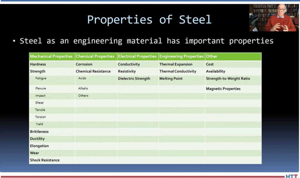
 DH: Well, think of it this way, Doug: When we have a steel, its microstructure, if it isn’t hardened, its microstructure is typically body-centered cubic, which means the atoms are all lined up in a certain structure. Now, what we do when we heat it up is -- when it gets above the transformation temperature (that dotted line, for simplicity, in this example) the atoms will realign themselves from body-centered cubic to face-centered cubic and a face-centered cubic structure is called austenite. Then, when we quench it, until we move into the nose of the curve or past those red lines, we still maintain an austenitic crystal structure as we’re cooling. The ferrite, the pearlite and things occur when we cross over into those reddish lines in that area there.