HARDENING TECHNICAL CONTENT

Heat Treat Radio #44: Rethinking Heat Treating (Part 4 of 4) — Direct from the Forge

In this episode, Heat Treat Radio host Doug Glenn talks with Joe Powell of Integrated Heat Treating Solutions in this fourth and final episode about bringing heat treating into the 21st century. This episode covers Direct from Forge Intensive Quenching – forge shops, listen up!

You are about to listen to the 4th and final episode in a series on rethinking heat treatment, with Joe Powell, of Integrated Heat Treating Solutions.  You can find the previous episodes at www.heattreattoday.com/radio.

Below, you can either listen to the podcast by clicking on the audio play button, or you can read an edited version of the transcript.


The following transcript has been edited for your reading enjoyment.

DG:  Joe, if you don't mind, take us on a 30,000 foot overview of what you've been doing at Integrated Heat Treating Solutions.

JP:  What we've been doing for the past 23 years at Integrated Heat Treating Solutions and the last 75 years at Akron Steel Treating is applying heat treatments to parts made by others.  We had over 1200 customers on our customer list at Akron Steel Treating and they use various materials.  We kind of grew up in the shadow of the Cleveland market, which is the largest market for heat treaters, and there is the largest number of commercial heat treaters in the Cleveland market.  This was possibly outnumbered by Detroit at one time, but I still think that we're probably the number one market for heat treating in this part of the country.

What has happened over the last century, in the 20th century, is that heat treating has become very, very good.  New equipment has been developed like controls, thermocouples, oxygen probes, vacuum furnaces, vacuum quenching, high pressure vacuum quenching, oil skimmers, new quenchants made with reverse solubility polymers - all of these things have come together and made heat treating very, very good.  However, as part of that, there has been a commoditization of heat treatment.  That means that heat treating became so good that parts rarely crack or distort unacceptably, and companies have devised methods for correcting the distortion through hard turning, grinding, straightening, flattening, you name it.  And the part makers and the heat treaters got along, in a kind of peaceful coalition, to get the parts out the door to the end user.

However, in the 21st century, that is just not good enough.  In lean manufacturing, you have to offer an integrated solution for what you're doing.  The entire value chain for making a product has to be on the same page; they have to be in alignment.  The processes have to be in the proper order.  What we're trying to do with Integrated Heat Treating Solutions is bring the last dimension of part design, what we call the Z dimension, to the part makers, their designers, and their material suppliers, so that we present a solution that delivers the optimal amount of value and eliminates the waste from heat treatment, or forging, as we'll talk about today.

[1] Defense Logistics Agency, "About," https://www.dla.mil/AboutDLA/
[2] DFIQ FIA Technical Committee Presentation, "Evaluation of Intensive Quenching Hardening Process Immediately After Completion of Hot Forging Operations," 2018.
[3] Forging Process Improvement Using Intensive Quench, 2019.
DG:  Right. In these four episodes we've been talking to people about bringing heat treating into the 21st century.  On your website, integratedheattreatingsolutions.com, there is a good illustration table that shows what heat treating was like in the 20th century and what it is like in the 21st century.  That's basically what we're talking about.  Just a quick recap of the previous three podcasts we've done: It all revolves around a customized heating, but more importantly, a customized quenching of materials so that the distortion of those parts is predictable, and that the part design can be altered so that there is essentially no post heat treatment processing.  In other words, you can pretty much eliminate grinding or any type of machining, straightening, and that type of thing.  Once heat treated and quenched with the technologies that you're talking about, the part is essentially pack and go.

We've talked about several examples, but the two we talked about in the recent podcasts were an 18” bevel gear, which was quite interesting.  Then we talked about a fracking pump valve seat, which was also quenched in this way.  So today, you and I want to talk about, as you alluded to, the forging industry.  We're going to talk about something called (direct from the) forge intensive quenching (DFIQ).  If you don't mind, tell us what that is.  For those people in the forging industry, what is direct from forge intensive quenching?

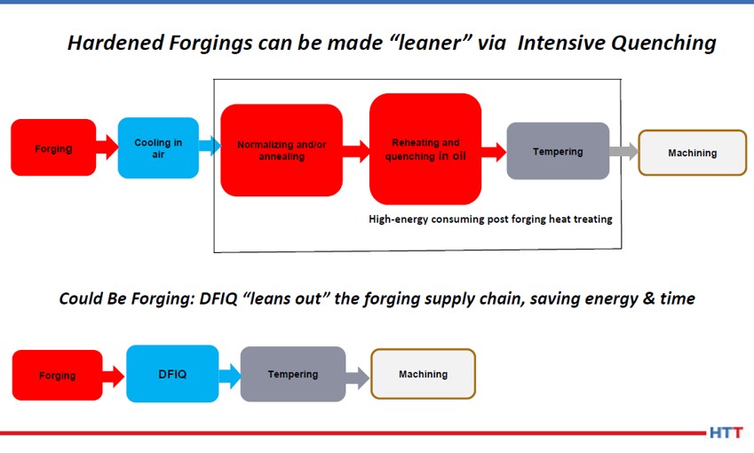
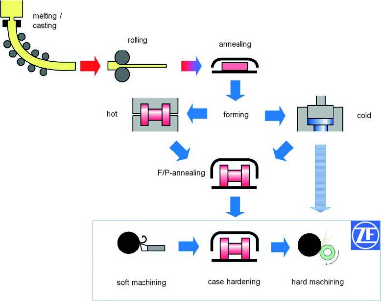
JP:  It's the principle that the forging processes use a lot of BTUs of heat to heat up a billet, and then bang it into a shape and get the grain flow going in the direction that will be great for the part mechanical properties.  Once that forged shape is attained and the grain flow is attained, the part is usually allowed to cool at the end of the forging trim die line, and those cooling forgings will all cool at different rates.  Because they cool at different rates, you have some fast cooling on the surface, the corners and the thin sections; but you have some very slow cooling in the core.  At the end of the day, the part needs to be heated a second time in a normalization process, which heats the part to a high temperature and then does a controlled cooling of the part to align the grains of the part and the size of the grains to remove the kind of mishmash of structure that is present in an as-forged part.  Then, if the part is going to be hardened at some point, and usually there is a lot of rough machining that goes on to remove the scale from the forging process, machining is necessary to remove the scale from the steel mill that has basically been hammered into the surface of the forging.  All of that rough machining is done to basically present a rough machine part that can then be heat treated.  So, companies like Akron Steel Treating or the captive heat treats at the forging plants will then heat the part a third time to the austenitizing temperature. If the part is made out of a martensitic steel, they'll quench it, usually in oil or polymer, and then possibly temper it to stabilize the part, and present it to the part maker for final machining, grinding and whatever final processing needs to be done to turn that forging into a useful part with the desired mechanical properties.

Akron Steel Treating doesn't do a lot of forged heat treat.  We do some aerospace parts for braking systems for airplanes, called torque tubes, which is basically the hub of the braking system.  Those torque tubes are generally made out of forgings which we see after forging, and then see again after 50% of the material is removed. Then the part is heat treated. In those instances, direct from the forge intensive quenching is not going to work.

Direct from the Forge Intensive Quenching

This direct from the forge intensive quench (DFIQ) project came out of a desire by the Forging Industry Association (FIA), which incidentally Akron Steel Treating has been a member since 2012.  We've always felt that we could create more streamlined processing as well as a better part with leaner material if we worked together with the forgers and integrated the heat treat process with the forging process. Companies like the TimkenSteel Company have come out with low alloy materials that are forged all the time, and then they do a controlled cooling where they'll actually air cool the forging.  With the alloying elements that are in there, they are able to come up with mechanical properties directly from the forge after a controlled air cool.  No normalization is needed and no further austenization, or third heating, is needed.  Basically, the part is air quenched and tempered right there in a controlled manner from the hot forge.

Some folks in India and Japan have tried several times to do direct from the forge liquid quenching using oils directly from the forge.  What they found is that the oil quench catches on fire, and if they can keep it from catching on fire by enclosing the quench under an inert atmosphere, they're still going to have the problem of the very high heat, like 2000°-2200° F, creating a steam blanket of hot oil, or in the case of polymer water, a steam blanket of polymer water mix around the outside of the part. This then produces an inability to uniformly quench the part because the thin sections will very quickly quench out, the thick sections will sit there under a blanket of gas and essentially those two mixes of nucleat boiling - very fast evaporative cooling in the thin sections and a full-blown gas blanket on the thick sections - create a nonuniform shell around the outside of the forging.  As that part cools under that nonuniform shell, it is also going to thermally shrink in a nonuniform way.  Also, when it cools to the martensite start temperature, it's going to start transformation and face change in a nonuniform way in that shell.

The successes of direct from the forge quenching didn't happen until this project we started in 2015 with the Defense Logistics Agency (DLA), which “manages the global supply chain – from raw materials to end user to disposition – for the Army, Marine Corps, Navy, Air Force, Space Force, Coast Guard, 11 combatant commands, other federal agencies, and partner and allied nations,” and the FIA tech committee members who sat down and asked: “Do you think we can do this in water?”  If we can do it in water, we obviously eliminate the fire hazard, but how do we eliminate the boiling hazard, or the boiling issue in the nonuniformity?  And that's where we had, at that time, 15 years of experience in applying the intensive quenching process or intensive quench process.

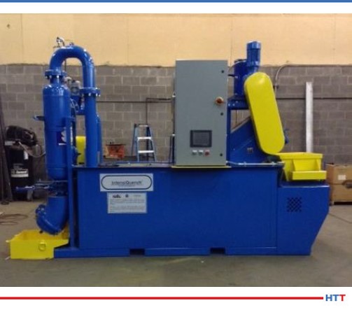
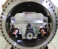
Luckily, John Tirpak, who was then working with the DLA and the FIA as a technical advisor, saw the benefit in giving it a try.  We had done lots of parts that people had said, over the years both at Akron Steel Treating and Euclid Heat Treating, couldn’t be done.  And we did it.  We applied it in the case of the valve seat to ductile iron to replace an 8620 carburized seat.  So, we have this great flexibility, we have this great new tool, we just need to use it, or at least try it, at the forge.  And that's what the DLA funded.  They basically gave us a budget for the building of a prototype unit which was built and is pictured in the final report It shows the test parts that were actually quenched directly from the forge at Bula Forge in Cleveland, and then we moved the prototype unit next to Welland Forge in Canada and finally to Clifford-Jacobs Forge in Illinois.

The upshot of all of this was that once we figured out that if we could remove the film boiling from the outside of the hot forging, we could basically set the shell, and once the shell is set, we get, on most parts and most geometries, a martensite shell that is formed.  That martensite shell continues to form down into the layers of the onion below the surface as the martensite temperature is reached and that martensite transformation continues by conduction, very uniformly through the mass of the part.  What you end up with is a part that comes out of the quench pretty much like it went through a normalization process and then a third reheating and an oil quench and a temper.  We get some self-tempering as well because we interrupt the intensive water quench before the part is fully cooled.  Nonetheless, we found in the first phase of testing that parts should be tempered in a tempering furnace to develop the full effects of the tempering process, so that process is still done after the parts come out of the quench.  But you eliminate the normalization process and the third reheating for an oil quench and temper that would normally be required.

Examples of DFIQ equipment
(Photo source: Joe Powell)

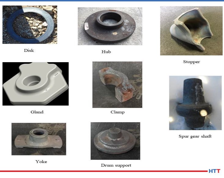
DG:  Can you tell us what parts were actually run?

JP:  Yes, there were a variety of parts, and they're all pictured in that report.  They ranged from a link that weighed, I believe, close to 50 pounds all the way down to a tine that was on a tiller machine (ground engaging tool) that went into a piece of farming equipment.  One of the parts in between was a pintle adapter that was basically a mounting post for a machine gun for the Army.  This part went through several operations.  It's documented in the report, but we basically saved $13 per part to the Army by eliminating the multiple steps that took place after forging and just incorporated it into an integrated heat treating solution right there at the trim die.

DG:  How did that look?  Let's take the tine, for example.  It's stamped out on a forge press.  You've got a hot piece of metal put on a forge press stamped out.  Then, one at a time, these parts are taken off of the forge press and immediately put in a quench?

JP:  After they come out of the trim die, they're still pretty hot - they're still austenitic, and range in temperature from like 1900°F all the way up to 2200°F - and then they go directly into the quench.  15-45 seconds later another one comes out of the trim die and goes down into the shoot and up the conveyor and into a box to await tempering.  We time the conveyor so that the dwell time in the intensive water quench is properly timed so that the core still has enough heat to self-temper, but not too hot that it over tempers the part.

DG:  I'm curious about the part.  After the part comes off the trim die, is it manipulated?  Is there a manipulating hand that comes in and grabs it, takes it off, puts in the quench tank?

JP:  In the case of the prototype, the manipulating hand was the forger.  He came with tongs and provided a very 19th century placement of that part.  But, obviously, all of this stuff can be automated and integrated, and with the proper equipment can be done in a way that is seamless from the time the billet is heated all the way through.

DG:  Tell me this, that tine again, when the guy took it off the trim die, did he just throw it in an intensive quench tank or was it fixtured?

JP:  Picture an elevator platform.  It was placed on an elevator and then the elevator went down between two panels that presented water at very high flow to the part and knocked off the film boiling.  I should add, the tine was the thinnest part and the enthusiasm at Clifford-Jacobs was very, very high because once they figured out that this worked, the guys on the floor said, “Let's try this part, let's try that part, let's try this part.”  And of course, in the first test at Bula Forge, we actually tested at least four different alloy materials and so all of those variables would have to be integrated into the design.  I call it the Z dimension of the design.  You pick the right material, you have the right forging temperature of the billet, and you don't overheat it.  One of the lessons learned in the four-year study is that if you overheat the forging to “help with die life” - that overheating of the forging to 2400°F (almost to the melting point) - the grains blow up.  No amount of intensive quenching is going to bring them back.  So, you've got to keep the temperature around 2150°F; that's about the maximum in Fahrenheit.

All I can say is that if you maintain a forging temperature uniformly around 2150°F in the billet, we can devise a quenching system that will blow the film boiling off and set that shell in the part in all but the thinnest parts in the prototype.  We did about 150 tines in a row with the protype, and then the water heated up because we only had so much chilling capacity in the water tank.  But as the water heated up, the quench wasn't as effective, and the tines actually exhibited some cracks when we ran another 150 - that's because there was film boiling in the mounting holes.  The lesson learned was you have to have a flow, but you also have to have some pressure in order to instantly impact that part.  That instant impact is key in the proprietary processes that Integrated Heat Treating Solutions is developing to bring the next version of the DFIQ unit to make it able to do the thinner parts without cracking.

DG:  DFIQ, of course, standing for direct from forge intensive quench.

You've referred to a study multiple times and that study is a 2019 study called, Forging Process Improvement Using Intensive Quench.  It looks like that was, as you mentioned, funded by the DLA in either 2014 or 2015. We will make that report available and people can take a look at it.  Anyone that is a forger in a forge shop, or a captive forge would certainly want to take a look at that.  Would forge press companies be interested in this?  Could they build quenches into the actual press itself so that this process could be, more or less, in line?

JP:  Yes, absolutely.  Again, it is a different paradigm for them.  Just like I mentioned before, all the heat treating equipment makers call themselves furnace companies and all the forging equipment makers call themselves press makers or forging die makers.  The reality is the process continues and the mechanical properties in the setting of those grain flows happen in the heat treating process; the refinement of those grains happens in the heat treating process which happens in the quenching process.  So, again, we need to integrate that quench into the forming equipment.  Again, I have no intention, as Integrated Heat Treating Solutions or Akron Steel Treating, of getting into the business of building systems- that's not my thing.  My thing is  to develop a robust process that can be applied and implemented using automation and new equipment with the proper pumps and material handling that is all integrated into a seamless process.

DG:  Let's talk very briefly about the benefits.  We've already alluded to quite a few of them, but let's try to enumerate them here.  What are the benefits to a captive forge shop in considering a DFIQ type system- why do it?  What's the commercial value?

JP:  We can save up to 66% of the energy that's needed to heat treat that part.  The part comes off the trim die and is cooled in a box or set aside somewhere.  Next, it needs to be reheated and normalized.  Then, it has to be reheated a third time and austenitized before quench and temper, and that's a lot of energy.  And it's also not usually done at the forge plant.  It's usually done either at a captive heat treat that is integrated with the forging company or it goes to a commercial heat treat where they use huge continuous furnaces to reheat the parts and quench and temper them.  I'm not going to make a lot of friends in the areas that do this, but if we're going to compete in the world and make great parts, be lean, save energy, and also have safe carbon emissions, we've got to stop heating parts that don't need to be reheated if you can avoid it.  I'm not going to claim that it works on each and every part and that it should be used for each and every part.  I'm just saying that there's a lot of parts that could be made a lot more efficiently if we would quench them right at the trim die.

DG:  So, one of the benefits you just mentioned is potentially saving 66%, basically two-thirds, because you don't have to do a second and third heat.  What else do we have?

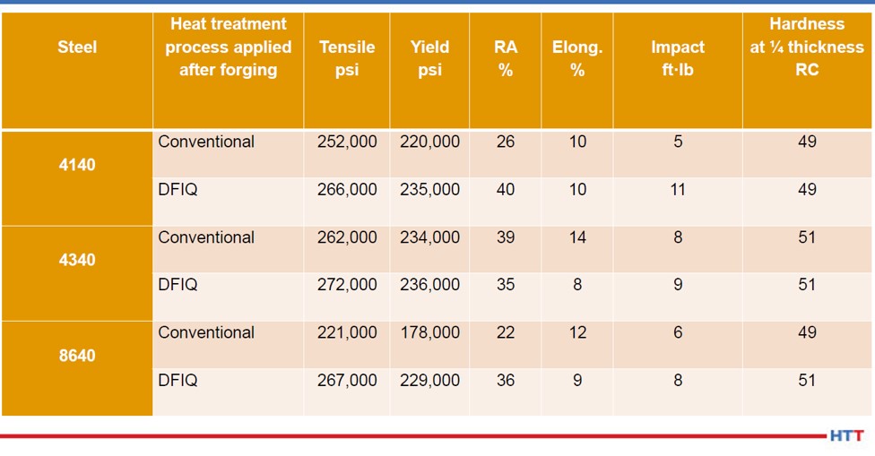
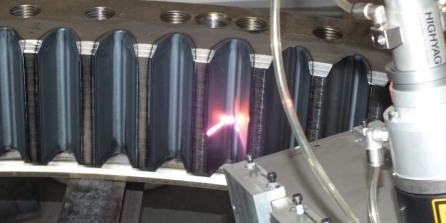
JP:  What you can have is better uniformity of mechanical properties. You can also elicit more hardenability out of a particular alloy by having this higher ability to harden with a very, very fast quench.  That intensity of quench locks in mechanical properties that are unattainable in a typical oil quench or polymer water quench. One example of that is a forging that we do for a company, in fact it was one of the companies in the study.  It's a 44” gear rack- it's 44 inches long, about 5 inches wide and about 4 inches thick. This gear rack is used as a piece of mining equipment and actually 10 of them are used on each side of a tower.  This gear rack allows the spinning, drilling rig to go up and down and spin as it is drilling holes in the earth.  This part was traditionally made from 4330 material but the end use customer, the people using this piece of mining equipment, said they’d really like to be able to replace and repair these gear racks when they get worn or a tooth gets broken.

If we could do this in the field, that would be great; but with 4330 material, we can't because we have to pre- and post-heat the weld when we replace or repair a tooth in the field. That’s just not practical in some cases, especially if this piece of equipment is on the side of a mountain and it's pretty cold outside.  So, is there a way to get field repairability?  That's a topic the DLA is very interested in because equipment used by the Army is often times used in very cold environments, so is there a way to repair that piece of equipment without taking it offline or bringing back for repairs?

For this particular gear rack, after they forged it to a rough shape with the gear teeth in on one side and it looked pretty much like a gear rack that was ready for rough machining, they wanted to be able to still get the same mechanical properties from a leaner hardenability steel like 4130 to replace the 4330, so that they could weld it in the field without pre- and post-heating to avoid cracking the part for the weld.  They came to us at Akron Steel Treating and they asked if we could this with our 6,000-gallon batch system.  We didn’t know.  I took a look at the jominy curve for 4330 and the jominy curve for 4130 and said it's going to be close. The thing is 4” inches thick by 5” wide, and I just didn’t know.  But I was willing to try. That has always been my favorite answer, “Let's try it.” If it blows up or it doesn't work, I'm going to learn something.  You might not be happy because I blew up your part, but I learned a lot and I'm happy and we're going to move on.

So, they gave us five actual parts made out of 4130 and we heat treated them in our 6,000- gallon system. Next, we sectioned them and found that they turned out very, very uniform.  They had the right surface hardness all over the part and also had the right core hardness throughout the 44” length.  Then they did some field trials, and everybody was happy.

DG:  So, in that case, the benefit is potentially being able to replace higher alloy parts with lesser alloy parts, field repairability, lower cost to manufacture the part, and easier to machine. You also talked about the fact that you can do significant energy savings which also potentially shortens the lead time because you're not having to go through two or three processes, but only one.  The one thing we haven't mentioned, which I think probably should be mentioned explicitly, although we've alluded to it, is the elimination of some environmentally unfriendly quench media.

JP:  It's a water quench.  You use just a little of restorentative salt and that's it.  It's water.

DG:  And obviously you've got better mechanical properties which you've also mentioned.

JP:  There's one more chapter to this and it ties back to podcast #2.  First of all, we do these parts 15 at a time on racks in our controlled atmosphere furnace and then transfer all of them to the handling cart and quench them in our 6,000-gallon system.  We noticed that when they went into the quench, they were straight, but when they came out of the quench, they were all uniformly bowed about 1 inch at the middle of the 44” length.  We mentioned to the customer, that when it's time to redo these forging dies, they should bow the forging so that it comes out of the trim die with a 1” bow in the opposite direction. Once it quenches, it will quench to fit and be relatively straight and will avoid the cold straightening operation that is done after heat treat and temper to get the part straight enough so it can be rough machined.

Again, time savings as well as monetary savings and we're not imparting cold strains into the part that has been hardened after heat treat, which is a no-no, because those cold strains can find a discontinuity in the material or an inclusion, and the two combined can, once in a great while, literally blow up as it is being straightened and fly across the room into two pieces.  Cold straightening is something you want to avoid if at all possible.

DG:  So, again, the benefit there is that you can go back to the part designer and the heat treater.

Let's back out again to 30,000 feet.  We're not talking about the gear racks anymore, just talking generally.  In your concluding thoughts, what is the main message we're trying to communicate here?

JP:  The integration of lean and heat treating and forging.  I think bringing all that together, all of that lean thinking and applying it to the part design at the front end, and the material selection at the front end, so that we deliver the most added value with the least amount of waste in the process to the end user.

DG:  I would like to wrap up by saying this too, there are a large number of people who are in the Heat Treat Today audience that I think ought to be interested in this.  Basically, anybody who is a captive heat treater, manufacturer with their own in-house heat treat who is doing oil quenching, or anything of that sort, and currently doing it in batch, ought to be thinking about contacting Joe to see if they can eliminate that batch process and put the heat treat directly in line.  Those are manufacturers.

Also, as we just talked today- the forging shops ought also to be interested in this.  Taking forge parts of the finish/trim forge and putting them directly into a quench.  But there is one other group that also ought to be interested in this and ought to be talking to you Joe, and that is the heat treat equipment manufacturers who have a stake here.  They have a stake here because their current batch processes, if we continue to move down this path into the 21st century, they could be on the cutting edge of providing the type of equipment that can be potentially more inline and more quench type equipment.  For what it's worth, I think that's worth mentioning.

JP:  Yes.  The 21st century of heat treating is moving towards induction heating and individual part by part quenches.  That is really the only way to control distortion consistently, and also to effectively get the most that an alloy hardenability has to offer for the end user, in terms of strength and ductility.

DG:  If these people want to get in touch with you, Joe, what's the best way for them to do that?

JP:  Through the website integratedheattreatingsolutions.com or ihtsakron.com.  The other person who is working with me very closely in the FIA technical committee is Rick Brown.  Rick Brown is a former executive at TimkenSteel here in Canton, OH.  He helped develop a supply chain for making parts out of seamless tubing that Timken made and still makes, and that supply chain included not only cutting up tubing into rings and making parts out of those rings, but also heat treatment, and in some cases, forging.  Rick has a wealth of experience.  He's a great guy and is one of our Integrated Heat Treating Solutions consultants who helps people at the part makers, part designers and end users get the most value out of the heat treating and forging processes. We're all working towards that goal of moving heat treatment from the 20th century fully into the 21st century.


Resources:

[1] Defense Logistics Agency, "About," https://www.dla.mil/AboutDLA/

[2] DFIQ FIA Technical Committee Presentation, "Evaluation of Intensive Quenching Hardening Process Immediately After Completion of Hot Forging Operations," 2018.

[3] Forging Process Improvement Using Intensive Quench, 2019.

(photo source: janjf93 at pixabay.com)


Doug Glenn, Publisher, Heat Treat Today

Doug Glenn, Heat Treat Today publisher and Heat Treat Radio host.


To find other Heat Treat Radio episodes, go to www.heattreattoday.com/radio and look in the list of Heat Treat Radio episodes listed.

Heat Treat Radio #44: Rethinking Heat Treating (Part 4 of 4) — Direct from the Forge Read More »

Heat Treat Basics: What’s Happening to Metals During Heat Treatment

Best of the WebSource: Advanced Heat Treat Corp. Blog

Graphic of Atomic Structures (Photo Source: AHT Blog post “What’s Happening to Metals During Heat Treatment”)

For this Heat Treat Today Technical Tuesday, check out this Best of the Web primer if you are looking to share a few basic pieces of heat treat info with your trainees. These heat treat fundamentals are about what happens to metals in the heat treatment process, tracing steel heat treating back to the ancient Romans in 223 B.C. — though, Encyclopedia Britannica currently places the origins in Egypt by 900 BC. Heat treatment benefits, atomic structural transformation, and hardenability are all covered here.

An excerpt: “Not every steel reacts the same. Chemical composition can vary greatly between the different grades of steel. Certain alloying elements can greatly increase the hardenability of steels such as nickel (Ni), chromium (Cr) and molybdenum (Mo). Hardenability is not how hard a material is. Hardenability directly relates to the ability of a metal to form martensite and martensistic [sic.] structure upon quenching, which points to…”

Read more: “What’s Happening to Metals During Heat Treatment”

(photo source: Lance Anderson at unsplash.com)

Heat Treat Basics: What’s Happening to Metals During Heat Treatment Read More »

Enhancing Fatigue Strength and Saving Money

Source: Advanced Nitriding Solutions Blog

While salt baths and gas nitriding are time-tested methods for hardening, what about the stringent body depth, surface hardness and composite layer thickness requirements for gears, guides, and drilling tools?

(photo source: https://ansion005.wordpress.com/)

In this Heat Treat Today Best of the Web feature, Advanced Nitriding Solutions shares the advantages of the surface hardening process of ion nitriding with plasma ions. While this surface hardening process is typically applied on steel, the process is both informative and relevant to other materials in the heat treating processes.

An excerpt: "...the fatigue strength is improved five to ten times from its typical “raw” life, depending on the material and the construction of the part. Thus the fatigue strength is improved without distortion compared to other surface treatment methods, thus saving customers money."

Read more: "The Advanced Nitriding Process – Enhance Fatigue Strength and Save Money"


(photo source: https://ansion005.wordpress.com/)


Enhancing Fatigue Strength and Saving Money Read More »

Strengthen Your “Metal Matrix” with Precipitation Hardening


Titanium nitride precipitates in a precipitation hardened HSLA steel. Image copyright: University of Nevada, Reno via The Balance

Source: Multiple (see below)

You may know it by one name — Precipitation Hardening, or by another — Age Hardening, or Particle Hardening. Whatever term you use, if you are employing this process to strengthen aluminum, titanium, or forms of alloys, the right balance between material and application will bring you the right results.

Precipitation hardening is a heat treating method used to strengthen metal components through the utilization of controlled release of solid impurities — or precipitates — to form precipitate clusters.

“The formation of these precipitates is accomplished by using a solution treatment at high temperatures prior to a rapid cooling process. The solution heat treatment results in a single-phase solution while the rapid cooling results in a stable material by preventing the creation and propagation of lattice defects. This greatly strengthens the metal matrix. 

Precipitation hardening is typically performed in a vacuum, inert atmosphere at temperatures ranging from between 900º and 1150° F. The process ranges in time from one to four hours, depending on the exact material and the characteristics specified.” ~ The Balance

The process generally follows three steps (per AZO Materials):

  1. Solution treatment at high temperatures
  2. Rapid cooling
  3. Heat treatment to induce precipitation

According to Bodycote’s website, where more information is given regarding the process details, the outcome varies depending upon whether a solution treating-only method is used or a combination of solution treating and precipitation age hardening.


Read more about the types of metals treated by precipitation hardening, techniques, industrial applications, and more:

“Learn About Precipitation Hardening” (The Balance)

“Age Hardening – Metallurgical Processes” (AZO Materials)

“Precipitation Hardening: Stainless Steels” (Bodycote)


Photo credit: Bodycote

Strengthen Your “Metal Matrix” with Precipitation Hardening Read More »

Age-hardening an Aluminum Underwater Buoy Frame

BOTW-50w  Source:  Metlabheattreat.com

Metlab recently assisted TrimMaster in fabricating an aluminum frame for an underwater buoy that would meet customer specifications. Mike Allard, Sales Manager, explains “We were faced with the prospect of welding the aluminum assembly to put it together, and knew that there would be reduced strength at the weld joint. By changing the welding wire we used, we could take advantage of Metlab’s heat treating process, especially their large furnaces to accommodate these parts, to raise the strength of all weldment components to a T-6 condition, giving us the strength that we needed for the application.”

Read More:  Age-hardening an Aluminum Underwater Buoy Frame

Age-hardening an Aluminum Underwater Buoy Frame Read More »

Distortion of Gears and Sliding Sleeves for Truck Gear Boxes – a Systematical Analysis of Different Heat Treatment Concepts


Schüler, J. Kleff, V. Heuer, G. Schmitt, T. Leist


A systematical approach regarding different distortion potentials in the process chain describes the influence on dimensional and shape changes of gears and sliding sleeves after case-hardening, like part geometry, cold and hot forming of blanks, carburizing concept and temperature profile, oil and gas quenching, as well as individual press and batch hardening. The results show an excellent potential of the new SyncroTherm® concept compared to the conventional case-hardening process for gears and sliding sleeves. Stable distortion characteristics even at elevated temperatures and without decreasing to hardening temperature as well as a good performance after two-dimensional batch quenching instead of the much more expensive individual press quenching were found in this study. Very sensitive part geometries are still a challenge. A clear limitation was found when processing cold formed blanks without annealing before soft machining.


Authors: Andreas Schüler, Dr.-Ing. Jörg Kleff, ZF Friedrichshafen AG, Alfred-Colsman-Platz 1, 88046 Friedrichshafen, Andreas.Schueler@zf.com (Corresponding  author)

Dr. Volker Heuer, Gunther Schmitt, Dr. Thorsten Leist, ALD Vacuum Technologies GmbH, Hanau


1. Introduction

Fig. 1. Process chain for transmission parts

Case hardening is the most common heat treatment for gears, shafts and synchronizer parts used in gear boxes for automotive and commercial vehicle applications. A combination of high fatigue resistance as well as good machinability and reliable process stability in heat treatment ensures transmission components with maximum strength, excellent performance and cost efficient production. In order to decrease the costs for hard machining and reduce the risk of grinding burns the knowledge of distortion characteristics for the individual part as well as distortion carrier potentials of the entire process chain is essential for an improved series production with minimum stock removal [1]. Even today with much higher requirements relating to lightweight design of automotive part geometries this aspect becomes more and more important [2]. Predictable and stable distortion characteristics are still a challenge especially for sensitive parts with thin cross-sections, non-symmetric design and a global production with many different suppliers in the process chain. In a constant pursuit for optimizing, ZF in Friedrichshafen investigated the potential of new heat treatment concepts with the advantages of reduced costs, quicker processes and less distortion. A comparison of the new heat treatment concept SyncroTherm® from ALD Vacuum Technologies was performed with the conventional benchmark concepts of a) case-hardening of gears in a pusher-type furnace with atmospheric gas carburizing and oil quenching and b) press quenching of sliding sleeves directly after gas carburizing in a rotary furnace. The “SyncroTherm®” heat treatment concept combines the benefits of smaller furnaces and two-dimensional batches, fast low-pressure carburizing (LPC) at elevated temperatures and reduced distortion by applying high-pressure gas quenching and the possibility of part-related individual quenching parameters [3].


2. Standard processes for transmission components at ZF Friedrichshafen

2.1 Material, forging and machining

The material for transmission components like gears and synchronizer parts is the case-hardening steel ZF7B which is a modified 20MnCr5. The process chain is shown in Figure 1. The material for automotive and commercial vehicle applications is usually continuously casted and formed to different bar geometries in the steel mill. The forging supplier performs either hot or cold forming of blanks. The gears investigated in this study were all hot formed and later F/P-annealed with an isothermal transformation in order to ensure a good machinability of the ferritic/ pearlitic microstructure. The forged blanks are soft machined by turning and teeth milling. Measurements of characteristic dimensions, shapes and teeth geometries were performed before and after heat treatment in order to describe the distortion behavior. Grinding the bore and teeth flanks is usually performed as the last process before assembling into the gear box. Two different process chains were investigated for the siding sleeve. The first one was similar to the gears with hot forming, F/P-annealing and soft machining. The other process chain for similar part geometry of the sliding sleeve was cold rolling and broaching of the internal spline without F/P-annealing. Different dimensions and shapes which are sensitive to distortion were measured before and after case hardening.


2.2 Case-hardening  in  pusher-type furnaces

The typical final heat treatment of gears is case-hardening in a pusher-type furnace. The gears are charged in three-dimensional batches of around 220 kg per batch including fixtures. The batches of helical and planet gears which were investigated in this study were loaded by different layers of gears on grids (Figure 2). Depending on the case-hardening depth with an individual cycle time the batch is pushed through the furnace with the different linked processes pre-washing, pre-heating at 480 °C, carburizing at 940 °C, decreasing to hardening temperature 850 °C, oil quenching, washing, tempering at 170 °C and cooling down to approximately 50 °C.

Fig. 2. Schematic depiction of pusher furnace (l.) and 3D batch of helical gears (r.)


Fig. 3. Schematic depiction of press hardening cell (l.) and press hardening tools (r.)


Fig. 4. ALD SyncroTherm® furnace (l.) and 2D batch of helical gears (r.)
Fig. 4. ALD SyncroTherm® furnace (l.) and 2D batch of helical gears (r.)


2.2 Case-hardening in rotary furnaces and press quenching

More distortion critical synchronizer parts, like the sliding sleeve, are carburized in a rotary furnace at 930 °C with different levels in the furnace.For a three-track press quench three parts are laying on a tablet and the tablet moves in a cycle time of approximately 70 s through the rotary furnace in order to achieve the required case-hardening depth of around 0.5 mm. The parts are quenched directly from carburizing temperature 930 °C and different tools are fixed to the part before quenching which is shown in Figure 3. During the quenching process the inner diameter of the sliding sleeve shrinks onto the mandrel with similar tooth geometry as the internal spline of the part. This behavior enables a constant inner diameter and position of teeth with less run-out and scattering. In order to adjust the flatness the sliding sleeve is pushed by a pressure piece onto the support ring during quenching. All tools are designed with oil drillings in order to achieve an efficient and uniform quenching of the cross-section. The distortion characteristics of press quenched parts are extremely depending on the design of individual tools and the quenching parameters like temperature and flow of the quenching oil or retention force of the pressure piece. Most synchronizer parts are ready for assembling after press hardening and shot blasting, no additional hard machining is performed anymore.


3. Investigation

The main idea of ALD-SyncroTherm® concept is a small and flexible furnace that can realize a quick low-pressure carburizing process (LPC) at elevated temperatures and reduced distortion behavior of the carburized parts by using an adjustable high-pressure gas quenching. Differently from the standard processes at ZF, parts are loaded in one single 2D-layer on light carbon-fibre tablets, as shown in Figure 4, and then directly heated up to carburizing temperature real quick, which can be up to 1050 °C. The LPC furnace with its small floor space of e. g. a turning machine has up to six single carburizing slots, where each tablet can be heat treated individually. After the carburizing process has been finished, the parts are transported to the internal gas quenching chamber where the parts are quenched directly from carburizing temperature (see Figure 4 left) [4].


Fig. 5. Time/temperature profile for helical gears with CHD 0.8 mm


Fig. 6. Analyzed parts: planet gear, helical gear and sliding sleeve (from left)


This is also a deviation to the direct batch quenching process at ZF where the part temperature is lowered to hardening temperature 840 °C before quenching with respect to distortion. Figure 5 shows a comparison of three different time/ temperature profiles which were tested within this analysis in order to achieve a CHD of 0.8 mm. The standard batch hardening process in a pusher-type furnace is compared to two different LPC processes with variation in carburizing temperature. In order to reduce distortion already during heating, the parts in the standard process at ZF are not being heated up to carburizing temperature directly but have a pre-heating step at 490 °C in order to equalize the core and surface temperature. For the LPC process with carburizing at 980 °C the overall process time is much shorter due to the higher temperature and the missing pre-heating step and the direct quenching from carburizing temperature. The reduced process time is even more pronounced when carburizing is performed at 1050 °C. All three profiles have been tested with different common parts for truck and bus transmissions. Figure 6 shows the three types of parts that have been chosen. The tests have been performed with a small planetary gear for bus transmissions and a heavier and bigger helical gear for heavy truck transmissions. Both gears are direct hardened at ZF by using the batch hardening process in a pusher-type furnace. Other experiments have been performed with two different types of sliding sleeves but similar geometry, as shown in Figure 6. Both types of sliding sleeves were processed differently: one type is machined from cold formed blanks whereas the other type is machined from hot formed and F/P-annealed blanks. Due to their high distortion potential, the standard process for sliding sleeves at ZF is carburizing in rotary furnaces with a consecutive press quenching. For each part many different dimensions, shapes and tooth geometries were measured before and after heat treatment in order to describe the individual distortion characteristics. Here, just critical features are shown which are representative for the distortion characteristics. For gears those are the internal diameter of the bore and the angular flank deviation fHb of the teeth. For the sliding sleeves the diameter of the internal spline and the flatness of the end face are the critical characteristics.


4. Results

4.1 Metallographic results

Metallographic results of the different tests were analyzed by investigation of one part from each batch since a correct metallographic result is the premise for the later analysis of the distortion and evaluation of the LPC process. Table 1 shows the different metallographic results of the analyzed parts from experiments at different carburizing temperatures and the results of the ZF benchmark processes, as a comparison. It shows that the LPC furnace is able to produce correct and repeatable metallographic results within specification regarding CHD, surface hardness and core strength.

Fig. 7. Grain sizes of planet gear after carburizing at 980 °C and 1050 °C

For bigger cross sections, like for the helical gear, the lower core strength is explainable due to the lower quenching speed of gas quenching compared to oil quenching in general and even further reduced gas quenching speed with respect to distortion of this gear. Additionally the amount of retained austenite could be maintained well within the required specification (max. 30 %) with the ALD furnace, even after quenching directly from carburizing temperature. Figure 7 shows micrographs of the grain sizes from core and surface samples taken from the heat treated parts with carburizing at 980 °C and 1050 °C and etched according to Bechet-Beaujard. Whereas the samples which were carburized at 980 °C show a homogeneous distribution of fine grains with grain size classes 5 and finer, the samples carburized at 1050 °C show an inhomogeneous distribution and very coarse grains with grain size classes up to 1 and coarser. These findings where confirmed through all performed experiments. This shows that conventional ZF case-hardening steel grades can already provide grain size stability up to 980 °C but not higher. For carburizing the parts at 1050 °C significant grain growth will occur in conventional grades. In order to prevent coarse grains microalloyed case-hardening steels are definitely necessary in order to meet the grain size specification [5]. Even knowing this fact already at the beginning, distortion experiments were performed at the higher temperatures, nevertheless, in order to analyze also the effect of grain growth on the part geometry and on distortion characteristics after heat treatment.


4.2 Comparison of distortion results – internal diameter of planet gears

In order to analyze the distortion of the internal bore, it was measured in three different levels of the bore. Figure 8 shows the location of the measuring levels M1-M3 within the internal bore of planet gears and the respective results from the green parts (12 sample parts), the benchmark process (24 sample parts) and the LPC experiment at 980 °C (12 sample parts).

Table 1. Metallographic results


Fig. 8. Barrel shape of the internal diameter of the planet gear after direct hardening


Fig. 9. Comparability (l.) and Stability (r.) of the internal diameter at higher carburizing temperatures


Whereas the three average values of the green parts show a perfect cylindrical form of the bore with almost no scattering, the measurement of the ZF benchmark process carburized at 940 °C shows a clear barrel shape of the internal bore with higher scattering. The same shape change can be observed in the results from the LPC experiment, although the value of the shape change and the scattering is less pronounced. The significantly lesser scattering of the heat treatment distortion compared to the benchmark process was even realized during experiments with a high carburizing temperature of 1050 °C (see Figure 9 left). Moreover the average value stays on the same level as after the experiment at 980 °C even if a significant grain growth was determined with no negative influence on distortion characteristics. The smaller diameter of the bore compared to the ZF process is explainable with the direct quenching from carburizing temperature without lowering the temperature, as it is done during the ZF process. These results are very stable even after carburizing at 1050 °C and were confirmed by two additional batches with same heat treatment parameters (Figure 9 right).


4.3 Comparison of distortion results – angular deviation of flank line fHβ

The value fHβ describes the angular deviation of a measured line along the tooth flank (see Figure 10) from the theoretically defined line of the tooth flank. It was measured on the left and on the right flank of three teeth per gear with a distance of 120° on the circumference. The same teeth and flanks have been measured before and after heat treatment. The results show that the fHβ of both flanks is highly influenced by the case hardening process. If compared to the measurements of the green parts, where the average value of the deviation is almost 0 mm with a maximum range of 0.02 mm, the average deviation after the benchmark heat treatment  is 0.03 mm with a wide range for both flanks up to 0.08 mm.


Fig. 10. Comparison of flank line deviation of helical gear standard and LPC process
Fig. 10. Comparison of flank line deviation of helical gear standard and LPC process


Fig. 11. Comparison of flank line deviation of planet and helical gear


The results of the LPC experiments are comparable to the benchmark process and even slightly better. While average deviation of both tooth flanks is on the same level as the value after the ZF process, the range is slightly smaller. The maximum range for the LPC tests at 980 °C is 0.06 mm even if the parts were directly quenched from carburizing temperature. Figure 11 shows that the average angular deviation and the range are less influenced by the heat treatment concept and the carburizing temperature of the process. Especially for the LPC process, negative influences on distortion may be compensated by adapted and optimized gas quenching parameters. Comparing the much smaller planet gear (tooth width 34 mm, helical angle 7°) with the bigger helical gear (tooth width 50 mm, helical angle 23°) different characteristics regarding the average and range of angular deviation can be determined. The planet gear shows a similar average of fHβ before and after heat treatment for both heat treatment concepts and different carburizing temperatures. The range of fHβ is slightly increased after heat treatment and is similar for the benchmark and the LPC process. For the bigger helical gear it is different. The average of fHβ changes after heat treatment significantly and the range is much higher. There is also a significant difference between the benchmark and the LPC process for the average of fHβ but not for the range of fHβ. This is a clear indication for more sensitive distortion characteristics of the helical gear. The significant difference in distortion behavior is mainly influenced by the bigger helical angle of the wider helical gear compared to the narrower planet gear with the smaller helical angle [6].


4.4 Comparison of distortion results – sliding sleeves

Sliding sleeves are distortion critical parts and therefore are case hardened and press quenched as a standard process in the ZF Company. In order to define the distortion of sliding sleeves, the internal diameter and the flatness where investigated. Different from the batch quenching in the LPC furnace, both characteristics are being controlled during press quenching of the ZF benchmark process by using individual press hardening tools. The investigation has been performed with 10 pieces of green parts, 25 pieces for the benchmark process and 10 pieces for each of the LPC experiments. For a better comparability of the results, the values of the measurements have been standardized and fitted into the tolerance band so that a value of 0 mm indicates the exact center of the allowed tolerance.


4.4.1  Cold formed

The investigation of the sliding sleeves machined from cold formed blanks shows how the press hardening tools of the ZF benchmark process influences the internal diameter by forcing it to shrink onto a defined tool diameter of the hardening mandrel. The intended negative deviation of the green parts of 0.05 mm from the ideal diameter, based on long-term experiences, is corrected after the ZF heat treatment (Figure 12). Additionally the press hardening tools reduce the scattering of dimensional and shape changes to a minimum. The results after carburizing at 960 °C and gas quenching in a batch of the LPC furnace display a tremendous heat treatment distortion and scattering of results in a large range. Even with optimized quenching parameters the range is nearly 1.0 mm. The reason for this worse distortion behavior can be explained by the high amount of residual stresses after cold forming of the blanks which are not removed by later annealing and soft machining.


Fig. 12. Distortion results of the internal diameter (l.) and flatness (r.) of cold formed sliding sleeves


Fig. 13. Distortion behavior (l.) and stability (r.) of the internal diameter of hot formed sliding sleeves
Fig. 13. Distortion behavior (l.) and stability (r.) of the internal diameter of hot formed sliding sleeves


A heating experiment where the parts were heated up to 960 °C without carburizing and afterwards slowly cooled down to room temperature was performed. This test was done in order to define the amount of distortion that is induced by residual stresses from former process steps already during heating. It clearly shows a high distortion potential of the sliding sleeves machined from cold formed blanks. Whereas the average diameter does not change the scattering is very large and, with a range of 0.65 mm, almost as wide as after the complete process with carburizing and quenching (Figure 12 left). This assumption was also confirmed by the distortion analysis of the parts flatness (Figure 12 right) where similar distortion behavior can be observed. This means that, without controlling dimensions by hardening tools, sliding sleeves that are machined from cold formed blanks cannot be heat treated within the required specification.


4.4.2  Hot formed

The distortion of sliding sleeves machined from hot formed blanks with a later F/P-annealing before soft machining, which reduces the residual stresses from prior process steps to a minimum, is significantly different compared to the cold formed sliding sleeve without F/P-annealing like previously described. The average diameter of the sliding sleeve after the ZF benchmark process is located near the upper tolerance with a slightly wider scattering (Figure 13 left) than after the heat treatment of cold formed sliding sleeves. Even by using optimized hardening tools for each part geometry the individual distortion behavior depends also on the forging lot and hardenability of the individual steel heat. Although some parts were outside of tolerance the final gage test applied on these parts showed that they are still usable for assembly. The heating experiment in the LPC furnace without carburizing reveals a smaller distortion potential due to minimized residual stresses of the hot formed and F/P-annealed blanks. Looking at the range of the diameter, it is just slightly wider when compared with the range of the green parts. This minimal distortion regarding the range can be preserved even after a completed experiment with carburizing and optimized gas quenching. Still, without the limiting function of a hardening mandrel, the average diameter shrinks as much as 0.38 mm after the heat treatment (Figure 13 left). The reproducibility of the described behavior of the LPC experiment with hot formed sliding sleeves was confirmed by two additional experiments with carburizing temperatures of 960 °C and of 1050 °C (Figure 13 right). Even the sliding sleeves from the final test that were carburized at 1050 °C show an average diameter that remains stable at the same level as those carburized at 960 °C. The additional scattering, that results of a higher quenching intensity, is minimal and in total still less than the tolerance band width of 0.2 mm. Therefore, producing sliding sleeves with the LPC process that fit the requirement might be possible if the dimensions of soft machining are adjusted with respect to the distortion behavior after heat treatment. This conclusion bears the potential of reducing heat treatment costs for distortion critical parts made from hot formed and F/P-annealed blanks by replacing the cost intensive press quenching followed by washing and shot blasting with a batch quenching process in the LPC furnace. However, this potential has to be investigated more in-depth before changing the process chain.


5. Summary

This paper describes a systematical analysis of different distortion potentials for case hardening processes. Different influences on distortion characteristics were investigated and defined such as different part geometries, process chains, carburizing concepts, temperature profiles and quenching methods. The main focus was on the comparison of the new SyncroTherm® concept by ALD Vacuum Technologies GmbH with established case hardening processes at ZF Friedrichshafen AG. The results show an excellent potential of the new LPC concept for gears and sliding sleeves. Stable distortion characteristics even at elevated temperatures and without decreasing to hardening temperature as well as a good performance after two-dimensional batch quenching instead of the much more expensive individual press quenching were found. However, very sensitive part geometries, such as sliding sleeves, are still a challenge. A clear limitation regarding the SyncroTherm® concept was found for sliding sleeves machined from cold formed blanks without F/P-annealing before soft broaching the internal spline.


References

  1. Raedt, H.-W.: Initiative Massiver Leichtbau. Presentation HeatTreatmentCongress, 22-24.10.14, Cologne, AWT e. V., Bremen , 2014
  2. Zoch, H.-W.: Distortion Engineering – Interim results after one decade within the Collaborative Research Center. Proc. 3rd Int. Conf. on Distortion Engineering, 1416.09.11, Bremen, H.-W. Zoch, Th. Luebben (Eds.), 2011, p. 569‒579; Mat.-wiss. Werkstofftechn. 43 (2012) 1‒2, p. 9‒15, DOI: 10.1002/mawe.201100881
  3. Heuer, V.; Löser, K.; Schmitt, G.; Ritter, K.: Einsatzhärten im Fertigungstakt. HTM J. Heat Treatm. Mat. 68 (2013) 3, p. 113‒123, DOI: 10.3139/105.110184
  4. Heuer, V.; Leist, Th.; Schmitt, G.: Distortion control through synchronized vacuum heat treatment. Proc. 5th Int. Conf. on Distortion Engineering, 23-25.09.15, Bremen, H.-W. Zoch, Th. Luebben (Eds.), 2015, p. 183‒192
  5. Hippenstiel, F.; Kohlmann, R.; Bleck, W.; Clausen, B.; Hoffmann, F.; Pouteau, P.: Innovative Einsatzstähle als maßgeschneiderte Werkstofflösung zur Hochtemperaturaufkohlung von Getriebekomponenten. HTM J. Heat Treatm. Mat. 57 (2002) 4, p. 290‒298
  6. Heeß, K.: Maßund Formänderungen infolge Wärmebehandlung von Stählen.
  7. ed., Expert Verlag, Renningen, 2007. – ISBN 978-3-8169-3067-9


Bibliography

DOI:10.3139/105.110285

HTM J. Heat Treatm. Mat. 71 (2016) 2; page 90-98

© Carl Hanser Verlag GmbH & Co. KG ISSN 1867-2493


Distortion of Gears and Sliding Sleeves for Truck Gear Boxes – a Systematical Analysis of Different Heat Treatment Concepts Read More »

Coupling CFD and Oil Quench Hardening Analysis of a Gear Component

BOTW-50w  Source:  Thermal Processing for Gear Solutions

“The coupling of CFD and heat treatment analyses provides a more robust application of computer modeling to predict the latent heat release, distortion, and residual stresses during the quench hardening process.”

Read More:  Coupling CFD and Oil Quench Hardening Analysis of a Gear Component by B. Lynn Ferguson, Zhichao (Charlie) Li, David Greif, Zlatko Kovacic, Simon Urbas, Rok Kopun

Coupling CFD and Oil Quench Hardening Analysis of a Gear Component Read More »

Materials 101 Series from Mega Mechatronics, Part 4, Heat Treatment/Hardening

BOTW-62wMaterials 101 Series from Mega Mechatronics, Part 4, Heat Treatment/Hardening. (27 mins., 15 February 2014). This is Part 4 of a 6-video series for mechanical engineers. The videos cover 1.stress & strain, 2. ductility & toughness, 3. corrosion, 4. hardening, 5. failure analysis, and 6. surface finishing. (NOTE: 7 videos are listed in an early side in Part 1 on stress & strain, but we were able to find only 6 videos. It does not appear that the seventh video on thermodynamics was uploaded.) https://www.youtube.com/watch?v=ouMl5HaZ_HA

Materials 101 Series from Mega Mechatronics, Part 4, Heat Treatment/Hardening Read More »

Skip to content