A Magnitogorsk, Chelyabinsk (Russia) company has placed a new contract for the expansion of their existing HPH® Bell-Type Furnace Plant for Wire Coils with a company based in Essen, Germany. OJSC MMK-METIZ located in Magnitogorsk, Chelyabinsk region, already operates a HPH® Bell-Type Furnace Plant supplied by Tenova LOI Thermprocess in 2014. This plant consists of 2 annealing bases, 1 heating hood and 1 Jet-cooling hood with a maximum net charge weight of 36 tons of wire rod or drawn wire coils. It uses a hydrogen/nitrogen mixture as protective gas atmosphere and features a useable diameter of 3,200 mm and a useable height of 2,700 mm.
In the spring of 2019, a new contract was signed concerning the expansion of the existing plant by further 2 annealing bases, 1 additional heating hood and 1 Jet-cooling hood. The start of production of the new plant is scheduled for the beginning of 2020. Besides the spheroidization annealing of wire rod, this plant also carries out the recrystallization annealing of drawn wire coils with the HPH® (High Performance Hydrogen) annealing technology.
Stephen Kowalski, president of Kowalski Heat Treating, talks about how the family-owned company will streamline operations after adding three buildings next door from Conveyer & Caster to its other six on Detroit Avenue in Ohio City. (Photo Credit: Stan Bullard)
An Ohio City heat treating business recently purchased a neighboring company’s property. The transaction was advantageous to both parties; the owners made a good sale, and the new occupants gained plenty of space without relocating.
After moving to a larger location, Conveyer & Caster sold their three Detroit Ave. buildings to family-owned Kowalski Heat Treating, which now fills nine buildings purchased since their 1975 opening on that street.
“It’s wonderfully exciting,” Kowalski said. “We needed assembly and warehouse space and office space. That’s all there in the Conveyer & Caster buildings. And we don’t have to move.”
Dunkirk Specialty Steel LLC, a leading U.S. manufacturer of semi-finished and finished specialty steel products, unveiled several state-of-the-art upgrades and modernization efforts at its Dunkirk facility. These renovations are the result of a $10 million capital investment from parent company Universal Stainless and Alloy Products, Inc., and collaborative efforts by the County of Chautauqua Industrial Development Agency, City of Dunkirk Department of Development, and NYS Empire State Development.
The 800,000 square-foot facility has installed a new $10 million bar turn and burnish line, as well as a new General Electric phased array nondestructive testing system. The addition of the specialty equipment from Germany and Japan makes the Dunkirk-based unit finishing cell the most advanced in the United States.
“This is more great news for Chautauqua County,” stated Mark Geise, Deputy County Executive for Economic Development/CEO of the County of Chautauqua Industrial Development Agency, “and demonstrates how collaboration at all levels can reap rewards for the County and the region. Dunkirk Specialty Steel LLC continues to up their game, and we’re glad we could be a part of it. I just want to thank Dunkirk Specialty Steel LLC and their parent company Universal Stainless and Alloy Products, Inc.; our economic development partners; and the CCIDA staff for making this project a reality.”
This article continues the ongoing discussion on Equipment Selection for Induction Hardening by Dr. Valery Rudnev, FASM, IFHTSE Fellow. Dr. Rudnev previously reviewed equipment selection for scan hardening in three parts. The first part on equipment selection for continuous and progressive hardening is here; the second part is here. To see the earlier articles in the Induction Hardening series at Heat TreatTodayas well as other news about Dr. Rudnev, click here. This installment continues a discussion on equipment selection for continuous and progressive hardening applications.
Inductor Designs
So far, I have discussed the application of conventionally designed solenoid coils in continuous/progressive hardening applications. However, even multiturn solenoid-type coil geometries may have quite complex shapes accommodating the shape of induction hardened components. One illustration of this is shown in Figure 1 where two in-line multiturn solenoid-type inductors are used for heat treating of an irregular shape component.
Figure 1. Two in-line multiturn solenoid inductor of a complex shape. (Courtesy of Inductoheat Inc., an Inductotherm Group company)
Besides multiturn solenoid coils, channel-type multiturn inductors (also called slot or skid inductors) are frequently used in continuous/progressive heat treating. The channel inductor gets its name from its similarity to a long channel. This shape allows parts to be passed through the coil in a number of ways, such as a conveyor, shuttle, indexing, rotary or carousel table, turntable, or any other indexing system.
Channel coils permit easy entry and exit of the heated components to/from the inductor. Figure 2 shows images of some examples of multiturn channel inductors. The crossover ends of channel coils are bent away to allow the part to pass through. In some cases, the crossover ends are made high enough to ensure minimum impact on the heating of the part at the ends of the coil, minimizing electromagnetic forces when workpieces enter and exit the inductor. In other cases, the opposite might be true, and crossover coil regions play an important part in providing the needed temperature distribution.
Figure 2. Images of different examples of multiturn channel inductors. (Courtesy of Inductoheat Inc., an Inductotherm Group company.)
Channel coils are used to heat treat selected regions of parts, as well as entire components. These inductors are often used for through hardening, annealing, and tempering applications. However, if a specific case depth is required, rotation of the workpiece may be needed to even case depth.
Figure 3 shows a “state-of-the-art” continuous fed induction system for heat treating fasteners [2]. This system is adjustable for a wide range of fastener/bolt diameters and lengths (0.5–4.0 in. [12–102 mm]) and is capable of production rates of up to 600 fasteners per minute. The unique proprietary coil design developed by Radyne Corporation maximizes electrical efficiency and system flexibility while preventing stray heating of electrically conductive surroundings that may potentially cause undesirable heating of structures and malfunction of electronic devices. The rotary dial tooling is designed to accept bolt fasteners from the in-line vibratory feeder. The adjustable speed rotary table contains advanced safety features to prevent damage and meltdown.
The quench assembly allows adjusting the quench flow for the utmost in quench control. After spray quenching, parts are stripped from the traverse assembly and dunk quenched into the tank for final cooling to room temperature.
Figure 3 shows a “state-of-the-art” continuous fed induction system for heat treating fasteners [2].The tooling is designed with a quick change feature to ensure that all tooling can be changed for a different part size in less than 15 minutes. The system is controlled through a controls package and HMI for part setup and part storage of different programs. Through this HMI, the power source coil “Z” adjustment can also be stored and adjusted for different bolt lengths assuring superior quality fasteners. This unit includes four sizes of tooling required for the rotary heat treat fixture and the traverse tooling: M6, M8, M10, and M12.
Besides solenoid coils and channel inductors, other inductor styles are used including split-return, hairpin and double hairpin inductors, transverse flux, and traveling wave inductors. However, an application of those inductors is not as frequent for continuous/progressive induction hardening.
Aluminum Association Creates Registration System for Additive Alloys Beginning with HRL’s First-Ever 3D-Printed High-Strength Aluminum
HRL Laboratories, LLC, is commercializing its additively manufactured (3D-printed) high-strength aluminum, which has obtained the first ever registration of an additive alloy from the Aluminum Association. HRL will be granted registration number 7A77.50 for the aluminum powder used to additively manufacture the alloy, and number 7A77.60L for the printed alloy.
The Aluminum Association oversees alloy registration and product standards used throughout industry. The association’s new additive alloy registration system was launched in February 2019 in response to a growing number of additively manufactured alloys. The first to be registered was HRL Laboratories’ high-strength aluminum, the first alloy of its kind to be printable. (This breakthrough discovery was published in the journal Nature in September 2017.)
“Essentially, this will connect us to this particular alloy composition forever,” said Hunter Martin, the lead scientist on the HRL team that created the alloy. “These alloy numbers will always be trackable back to HRL, like a DNA signature. When I first contacted the Aluminum Association about registering our alloy, they did not have a way to register alloys printed from powders, so they decided to create a new system for registration of additively manufactured materials – a first in the materials space.”
Zak Eckel, another HRL team member said, “We’re in the process of commercializing this material, which is already in high demand. As we scale up to commercial levels, AA registration validates our product. Companies who want the powder for their 3D printers can ask for its specific number, and it becomes a true commercial alloy.”
As the aluminum industry’s leading voice in the United States, the Aluminum Association provides global standards, statistics, and expert knowledge to manufacturers and policy makers. Alloy and temper designations, chemical composition limits, and registered properties in North America adhere to those standards. The association also provides business intelligence, sustainability research, and industry expertise and is committed to environmental considerations while advancing aluminum as the sustainable material of choice around the world.
Heat TreatTodayoffers News Chatter, a feature highlighting representative moves, transactions, and kudos from around the industry.
Personnel and Company Chatter
Diane C. Creel was recently announced as independent Board Chair at Allegheny Technologies Incorporated (ATI) upon the retirement of Executive Chairman Richard J. Harshman.
A global company specializing in the manufacture of flow measurement instrumentation was recently acquired by The TASI Group. Sierra Instruments is comprised of two divisions: FLOW, headquartered in Monterey, California, and AUTO, headquartered in Malvern, United Kingdom. The FLOW Division manufactures mass flow meters and flow controllers for gas, liquid, or steam application. The AUTO Division builds complex, custom, integrated test facilities, and world-class engine and vehicle test automation systems.
StandardAero Component Services facility, located in Prahova, Romania, expanded its manufacturing capacity from 32,000 sq. ft. to 43,000 sq. ft. and also recently exceeded over 200,000 gate valves processed with High-Velocity Oxygen Fuel (HVOF) coatings.
A multi-year contract has been signed between American privately-funded aerospace manufacturer and spaceflight services company, Blue Origin, and Constellium N.V., to support their launch vehicle programs. This contract is a new milestone in a successful collaboration between the two companies for the supply of high-performance Airware® products. Under this agreement, Constellium is to supply Airware® aluminum plates and sheets for Blue Origin’s massive orbital rocket, New Glenn.
Diane C. Creel, independent Board Chair, ATI
Sierra Instruments acquired by The TASI Group.
Constellium and Blue Origincontract to support launch vehicle programs.
Equipment Chatter
A state-of-the-art hot isostatic press (HIP) with Uniform Rapid Quenching (URQ®) will introduce a new quality benchmark for the FIT Additive Manufacturing Group. Coming online in September 2019 in FIT’s main facility in Lupburg, Germany, the press from Quintus Technologies will enable the additive manufacturing (AM) specialist to boost productivity while responding to the heightened industrial requirements for 3D printed metal series parts.
A global manufacturer of cutting tools has purchased an additional vacuum temper furnace from Pennsylvania-based SECO/VACUUM, for its North American manufacturing operations. The new furnace, which will be used for tempering and stress relieving metal parts, is part of the company’s growing manufacturing expansion and complements another commissioned earlier in 2019 at this facility.
Hot isostatic press (HIP) with Uniform Rapid Quenching (URQ®) from Quintus Technologies
Vacuum temper furnace from Pennsylvania-based SECO/VACUUM
Kudos Chatter
Electro Tech Machining – Carbon and Graphite Innovation, which serves the heat treating industry among others, recently announced the launch of its new website: http://www.etmgraphite.com
Dana Incorporated has been named Outstanding Thermal Management Solutions Supplier of the Year by the China Decision Makers Consultancy (CDMC) for its work in 2018.
AMETEK SMP Superior Tube, a leading manufacturer of small diameter precision metal tubing for the aerospace and defense industries as well as other sectors, has announced two successful reaccreditations from Nadcap. Superior Tube met all Nadcap’s requirements based on the exacting standards around heat treating and welding/brazing.
Franck Adjogble and Wolfgang Spies, both SMS group engineers, received the AIST James Farrington Award 2019 in Pittsburgh, Pennsylvania, for their work entitled “Holistic Approach of High Quality Flat Steel Production – Dynamic Production Scheduling in Respect to Process Quality, Control System and Plant Condition”.
Electro Tech Machining – Carbon and Graphite Innovation launches new website
Brian Gorney and Scott Bussinge, AMETEK SMP Superior Tube
Franck Adjogble and Wolfgang Spies, SMS group
Heat TreatTodayis pleased to join in the announcements of growth and achievement throughout the industry by highlighting them here on our News Chatter page. Please send any information you feel may be of interest to manufacturers with in-house heat treat departments especially in the aerospace, automotive, medical, and energy sectors to the editor at editor@heattreattoday.com
A leading provider of precision parts recently announced the acquisition of two companies, both suppliers of tight tolerance, mission-critical components used in medical device, aerospace, and industrial applications.
MW Industries, headquartered in Rosemont, Illinois, which engineers springs, specialty fasteners, bellows, and other precision components has acquired both companies from SW Holdings, LLC: Marox, a manufacturer of machined orthopedic implants, and Sussex Wire, a manufacturer of mini and micro cold-formed parts.
John Bagnuolo, Chief Executive Officer of MW Industries
Located in Holyoke, Massachusetts, Marox produces precision machined orthopedic and spinal implants in a variety of complex geometries to leading orthopedic device firms. The company also manufactures components used on robotic surgery devices.
Sussex Wire, located in Easton, Pennsyvania, applies cold-forming and roll-forming manufacturing techniques to shape metal wire and special alloys into highly engineered, precision, micro-miniature components. These components play essential roles in medical device applications.
Both companies offer advanced engineering capabilities, material selection advice, and manufacturing know-how for creative solutions that shorten design cycle times and speed time to market.
“Adding Marox and Sussex Wire to our portfolio of medical solutions companies creates a set of technical capabilities and precision machining capacity that is unmatched in the industry,” explains John Bagnuolo, Chief Executive Officer of MW Industries. “Medical device OEMs and CMOs can rely on MW Industries for innovative, cost-effective solutions to their most complex design challenges.”
Heat treat equipment upgrades were included in the investments made at a global industrial solutions company that produces fasteners and fastening assemblies.
A. Raymond Tinnerman, based in Brunswick, Ohio, has seen significant upgrades and additions to its Logansport, Indiana, facility, which includes the rebuild of the heat treating processes and the addition of an endothermic generator.
A thermal process modeling company used its heat treatment simulation software to explore oil quench sensitivities on the distortion of a large landing gear made of 300M, a vacuum melted low alloy steel that includes vanadium and a higher silicon composition.
DANTE Solutions, an engineering consulting and software company specializing in metallurgical process engineering and thermal/stress analyses of metal parts and components, was approached to examine local stagnant oil flow and immersion, among other sensitivities, for this critical aerospace component.
Zhichao (Charlie) Li, Ph.D., vice president of DANTE Solutions, was the lead researcher and author of this study.
Case Study
Problem Statement
Part:
3 modes of distortion that are of concern
2.5 meter tall landing gear
0.25 meter main tube diameter
AISI 300M material
Problem:
Large distortions after oil quenching in the following distortion modes:
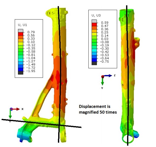
Bow in XY-Plane
Bow in YZ-Plane
Straightness of a Blind Hole
All distortion modes shown in the figures make assembly of the entire structure very difficult.
Immersion into the oil tank is the main focus of the distortion analysis.
Process Description
Part is austenitized in pit furnace at 1607°F (875°C).
A 45-second step is included for the removal of the landing gear from the pit furnace.
75-second open-air transfer from pit furnace to oil quench tank. The landing gear is immersed into the oil with a speed of 203.2 mm/sec, with the immersion direction shown in the figure. It takes 11.885 seconds to immerse the entire gear in the oil tank.
The landing gear is held in the oil for 5 minutes.
Tempering not considered, due to negligible effects on distortion.
Temperature (°C), Austenite (fraction), horizontal displacement (mm), and vertical displacement (mm) at the end of the immersion process; section cut, looking inside the part.
Model Description
Model contains 281,265 nodes and 258,272 hex elements.
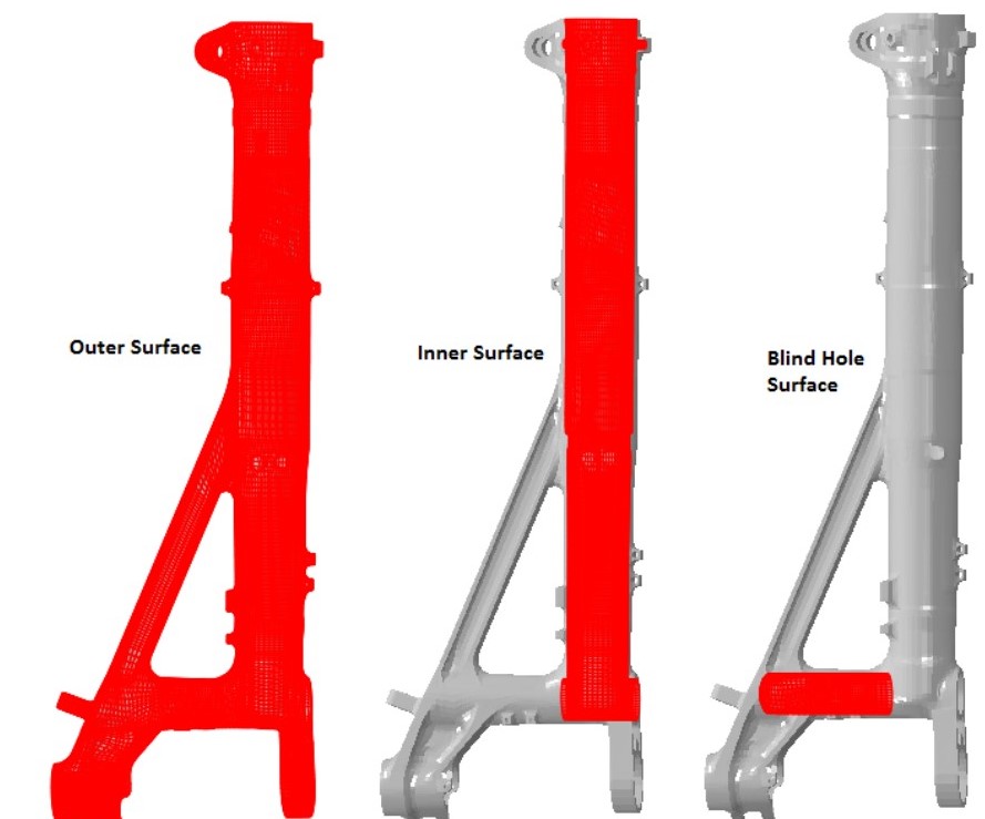
3 surfaces defined for heat transfer boundary conditions.
Oil flow stagnation is expected inside the main tube (Inner Surface) and the blind hole.
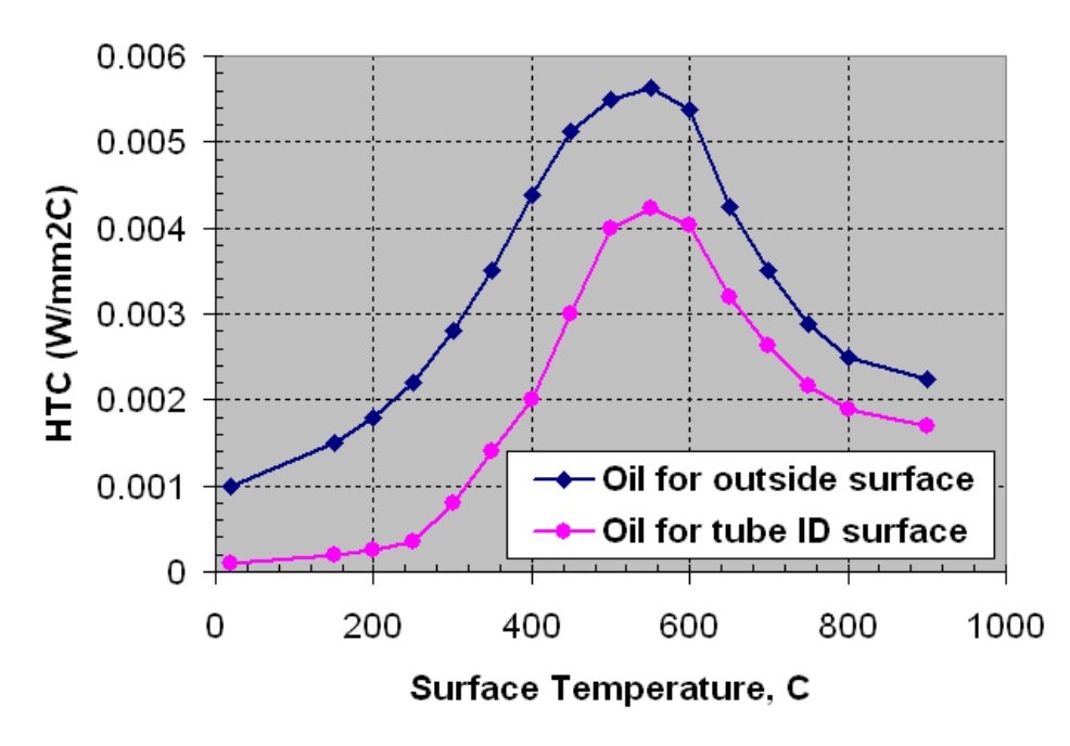
Different thermal boundary conditions are applied to the outer surface and the inner surface, as shown to the right.
The blind hole and the inner surface have the same thermal boundary conditions in the baseline model.
During immersion, oil enters the blind hole first and then begins to fill up the main tube.
In the baseline model, the oil level rising speed inside the bore is assumed to be 20% of the landing gear immersion speed.
Modeling Approach
Define heat transfer coefficients as a function of temperature for the oil tank.
Thermocouples placed at various locations on a dummy landing gear, which was
approximately the same overall dimensions and mass. Improve 300M material data in DANTE material database using dilatometry testing.
Improve 300M material data in DANTE material database using dilatometry testing.
Perform sensitivity study to determine phenomena critical to distortion modes of interest.
Oil flow stagnancy in blind hole during immersion: The more stagnancy, the lower the heat transfer on this surface. Baseline assumed to be the most stagnant. Two faster heat transfer rates examined.
Oil flow stagnancy around structural support arm: The more stagnancy, the lower the heat transfer on this surface. Baseline assumed to be least stagnant. Two slower heat transfer rates examined.
Oil fill rate of the main tube during immersion into the oil: The slower the oil fills up the main tube, the larger the temperature and phase transformation gradient is in the axial direction of the tube. Baseline assumed the slowest fill rate. Three faster fill rates were examined.
Immersion direction: Immersion direction sets up axial temperature/phase transformation gradients and also determines how the main tube is filled. The Baseline immersion direction causes oil to enter through the blind hole first and then into the main tube. Opposite immersion direction is examined, which causes oil to enter the open end of the main tube first.
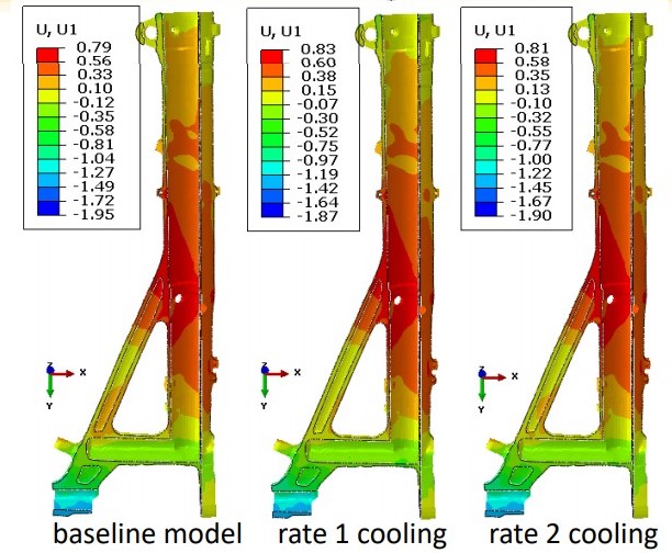
Blind Hole Quench Rate Sensitivity
Figure 8. Temperature (°C) in the blind hole at the end of immersion for the three cases.
Heat transfer is increased in the blind hole during the
immersion process; all other heat transfer rates
remain the same as the baseline model during
immersion.
All heat transfer rates are identical to the baseline
after the part is fully immersed in the oil.
Baseline model assumes blind hole heat transfer is
equivalent to the main tube inner diameter heat
transfer during and after the immersion process.
Rate 2 has a faster heat transfer rate than the baseline.
Rate 1 has a faster heat transfer rate than Rate 2.
Figure 8 shows a significant difference in temperature between the three cases at the end of the immersion process.
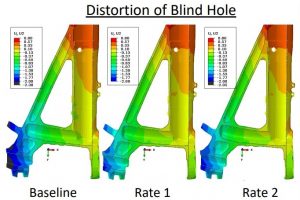
Heat transfer rates explored in the blind hole do not contribute
to the tilting of the blind hole.
Figure 9 shows that the angle of the hole is the same, regardless of the quench rate.
Modification of the blind hole to increase the heat transfer rate
in the hole to help improve the straightness of the blind hole is not necessary.
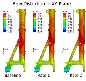
Heat transfer rates explored in the blind hole do not contribute significantly to the bow distortion in the XYPlane or the YZ-Plane.
Figure 10 shows that the bow distortion is made slightly worse by increasing the heat transfer rate in the blind hole during immersion, but is not significantly worse.
Modification of the blind hole to increase the heat transfer rate in the hole to help improve the bow distortion is not necessary.
Figure 9
Figure 10.
Structural Beam Quench Rate Sensitivity
Reduced heat transfer of the structural arm is examined.
Oil flow stagnancy is assumed to reduce heat transfer rate on arm.
2 slower heat transfer rates compared with baseline.
Baseline assumes the same heat transfer rate on the structural arm as on the main tube OD.
Figure to the left shows the reduced heat transfer rate surfaces of the structural arm.
Rate 1 is slower than Baseline.
Rate 2 is slower than Rate 1.
Figure below shows the temperature difference in the structural beam at the end of the immersion process.
Approximately 212°F (100°C) difference between Baseline and Rate 1
Approximately 392°F (200°C) difference between Baseline and Rate 2
Bow distortion in xy-plane has a non- Distortion of Blind Hole linear response to oil stagnancy around the structural beam.
Rate 1 produced the least amount of bow in xy-plane.
Baseline produces the greatest amount of bow in xy-plane.
Distortion of blind hole has a non-linear response to oil stagnancy around the structural beam.
Rate 1 produced the straightest blind hole.
Baseline produces the greatest amount of distortion of the blind hole.
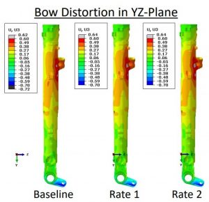
Bow distortion in yz-plane has no sensitivity to oil stagnancy around the structural beam.
The non-symmetric mass near the top of the landing gear has the most influence on the yz-plane bow distortion.
Figure 15 shows lower bainite phase fraction at the end of the quenching process.
Figure 15
Slower heat transfer rate of the structural beam results in significantly different amounts of lower bainite.
The slower the heat transfer, the more lower bainite formed.
Increased amounts of bainite reduce bow distortion in xy-plane, but the response is non-linear.
Rate 2 caused slightly more distortion than Rate 1, but less distortion than the Baseline.
Increased amounts of bainite reduce distortion of the blind hole, but the response is non-linear.
Rate 2 caused slightly more distortion than Rate 1, but less distortion than the Baseline.
Oil Fill Rate in Main Tube Sensitivity
The rate at which the oil fills the main tube is critical to the phase transformation timings and the phases formed.
The immersion speed of the landing gear is 203.2 mm/sec.
Baseline assumes the inside of the tube fills up at 20% of this value (40.64 mm/sec).
Three different fill speeds were explored:
50% (101.6 mm/sec)
100% (203.2 mm/sec)
200% (406.4 mm/sec) Assumes pressure build up forces oil up the inside of the tube.
Figure 16 compares temperature inside tube at end of immersion for four cases.
Figure 16
The oil fill rate of the main tube during the immersion process has a very significant effect on all three modes of distortion.
From top left clockwise
Bow distortion in yz-plane has a non-linear response to the fill speed (Figure 17)
50% produces the worst bow
100% & 200% are very similar, with 200% slightly worse
Bow distortion in xy-plane has a non-linear response to the fill speed (Figure 18)
50% produces the least bow
100% produces the worst bow
Straightness of the blind hole has a linear response to the fill speed (Figure 19)
Slowest fill speed has least distortion
Fastest fill speed has the worst distortion
Difference in lower bainite was the cause for differences in distortion with respect to oil stagnancy around the structural beam previously shown.
Differences in distortion from the oil fill rate of the main tube are not caused by microstructural phase differences.
Figure 18 shows that Martensite and Lower Bainite are the same for all fill speeds.
Differences in distortion are caused by the transformation timing along the axis of the landing gear.
Immersion Direction Sensitivity
Figure 19
Distortion sensitivity to the immersion direction was examined.
Figure 19 compares temperature profile at the end of the immersion process for the two immersion directions.
The Baseline has oil enter the blind hole first and then fill up the tube at a rate that is 20% of the immersion speed.
Oil spills over the top of the tube and the tube is flooded with oil.
The reversed immersion has oil enter the tube first and fills at the immersion speed.
Figure 20
Reversing the immersion direction also reverses the axial temperature gradient.
Martensite transformation starts at the open tube end when the immersion direction is reversed.
Martensite transformation starts by the blind hole first for the Baseline.
Reversing the axial phase transformation gradient can have significant effects on bow distortion and axial displacement.
Figure 20 shows the vertical displacement around the blind hole for the Baseline and the Reversed Immersion.
Reversing the immersion direction had a very minor impact on the straightness of the blind hole.
Closed side of blind hole was pulled further down by reversing the immersion direction, but the closed side
Figure 21
was not pulled up as much.
Figure 21 shows the bow distortion in the XY-Plane for the Baseline and the Reversed Immersion.
Reversing the immersion direction has a significant effect on the bow distortion in the XY-Plane, nearly doubling it.
Reversing the immersion direction has no effect on the bow distortion in the YZ-Plane.
Conclusions
Four process parameters were evaluated for distortion sensitivities for a large landing gear component:
Oil stagnancy inside a blind hole, oil stagnancy around a structural support beam, oil fill rate into the main tube as the landing gear is lowered into the oil tank, and immersion direction of the landing gear.
Three distortion modes were evaluated:
Bow distortion in XY-Plane, bow distortion in YZ-Plane, and straightness of a blind hole.
Bow distortion in the XY-Plane IS significantly affected by oil stagnancy around structural support beam, oil fill rate up the main tube, and the immersion direction.
Bow distortion in the XY-Plane is mainly controlled by the behavior of the structural support beam.
Bow distortion in the XY-Plane IS NOT significantly affected by oil stagnancy in the blind hole.
Bow distortion in the YZ-Plane IS significantly affected by oil fill rate of the main tube.
Bow distortion in the YZ-Plane is mainly controlled by a fitting near the open end of the tube that contributes to non-symmetric mass around the main tube in that area.
Bow distortion in the YZ-Plane IS NOT significantly affected by oil stagnancy in the blind hole, oil stagnancy around the structural support beam, or the immersion direction.
Straightness of the blind hole IS significantly affected by oil stagnancy around structural support beam and the oil fill rate up the main tube .
Straightness of the blind hole is mainly controlled by the structural support beam behavior.
Straightness of the blind hole IS NOT significantly affected by oil stagnancy inside the blind hole or the immersion direction.
Modifications to the quenching process were made to improve the distortion response of the landing gear.
Modeling results were used to direct the modifications.
Customer considered changes proprietary and did not share.
Benefit of using heat treatment simulation over physical experiments to perform sensitivity studies was shown.
Ability to modify, and see the effects of, just one process parameter with simulation is easy.
Ability to modify, and see the effects of, just one process parameter with experiments is very difficult, if not impossible.
A major steel manufacturer recently acquired certain assets from a carbon steel tubing provider that supplies induction heat-treated tubes for automotive applications.
Nucor Corp acquired the assets from Century Tube LLC, based in Madison, Indiana, which supplies carbon steel tubing for automotive and other mechanical and structural applications. The company offers round, square, rectangular, oval and other special welded shapes of mechanical steel tubing, and is a leader in supplying induction heat-treated tubes for automotive applications. Since 1993, Century Tube has produced more than 300 million door impact beams for use in Toyota, Honda, Ford, FCA, Subaru, Nissan, and Mitsubishi vehicles.


 Source:

![Figure 3 shows a “state-of-the-art” continuous fed induction system for heat treating fasteners [2].](https://www.heattreattoday.com//wp-content/uploads/2019/05/FIG_3.jpg)


 From top left clockwise


