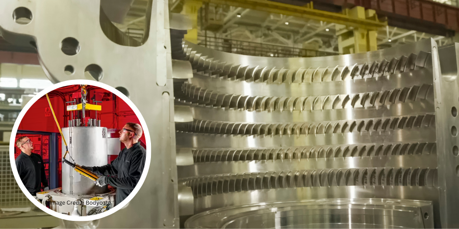
A thermal process modeling company used its heat treatment simulation software to explore oil quench sensitivities on the distortion of a large landing gear made of 300M, a vacuum melted low alloy steel that includes vanadium and a higher silicon composition.
DANTE Solutions, an engineering consulting and software company specializing in metallurgical process engineering and thermal/stress analyses of metal parts and components, was approached to examine local stagnant oil flow and immersion, among other sensitivities, for this critical aerospace component.
Zhichao (Charlie) Li, Ph.D., vice president of DANTE Solutions, was the lead researcher and author of this study.
Case Study
Problem Statement
Part:
- 2.5 meter tall landing gear
- 0.25 meter main tube diameter
- AISI 300M material
Problem:
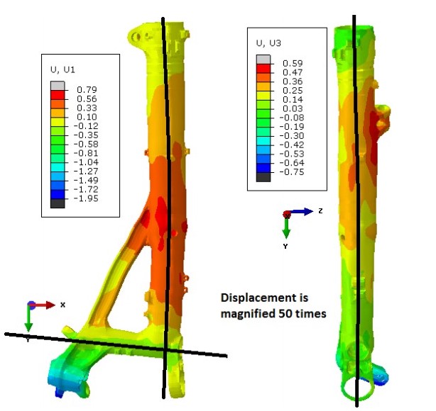
- Large distortions after oil quenching in the following distortion modes:
- Bow in XY-Plane
- Bow in YZ-Plane
- Straightness of a Blind Hole
- All distortion modes shown in the figures make assembly of the entire structure very difficult.
- Immersion into the oil tank is the main focus of the distortion analysis.
Process Description

- Part is austenitized in pit furnace at 1607°F (875°C).
- A 45-second step is included for the removal of the landing gear from the pit furnace.
- 75-second open-air transfer from pit furnace to oil quench tank. The landing gear is immersed into the oil with a speed of 203.2 mm/sec, with the immersion direction shown in the figure. It takes 11.885 seconds to immerse the entire gear in the oil tank.
- The landing gear is held in the oil for 5 minutes.
- Tempering not considered, due to negligible effects on distortion.

Model Description
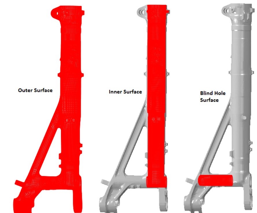
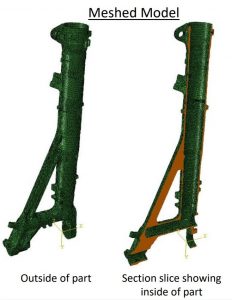 Model contains 281,265 nodes and 258,272 hex elements.
- 3 surfaces defined for heat transfer boundary conditions.

- Oil flow stagnation is expected inside the main tube (Inner Surface) and the blind hole.
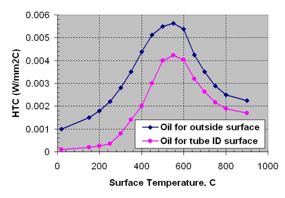
- Different thermal boundary conditions are applied to the outer surface and the inner surface, as shown to the right.
- The blind hole and the inner surface have the same thermal boundary conditions in the baseline model.
- During immersion, oil enters the blind hole first and then begins to fill up the main tube.
- In the baseline model, the oil level rising speed inside the bore is assumed to be 20% of the landing gear immersion speed.

Modeling Approach
 Define heat transfer coefficients as a function of temperature for the oil tank.
- Thermocouples placed at various locations on a dummy landing gear, which was
approximately the same overall dimensions and mass. Improve 300M material data in DANTE material database using dilatometry testing.
- Thermocouples placed at various locations on a dummy landing gear, which was
- Improve 300M material data in DANTE material database using dilatometry testing.
- Perform sensitivity study to determine phenomena critical to distortion modes of interest.
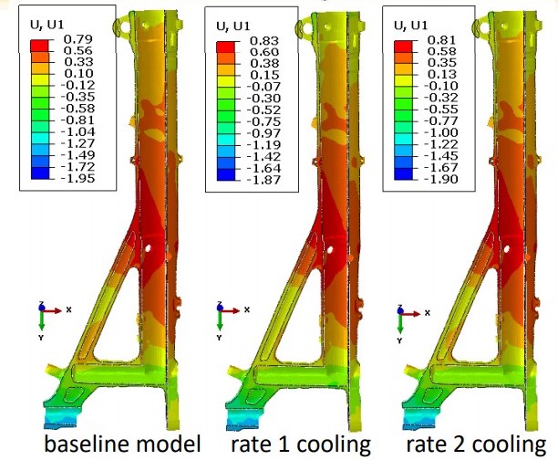
- Oil flow stagnancy in blind hole during immersion: The more stagnancy, the lower the heat transfer on this surface. Baseline assumed to be the most stagnant. Two faster heat transfer rates examined.
- Oil flow stagnancy around structural support arm: The more stagnancy, the lower the heat transfer on this surface. Baseline assumed to be least stagnant. Two slower heat transfer rates examined.
- Oil fill rate of the main tube during immersion into the oil: The slower the oil fills up the main tube, the larger the temperature and phase transformation gradient is in the axial direction of the tube. Baseline assumed the slowest fill rate. Three faster fill rates were examined.
- Immersion direction: Immersion direction sets up axial temperature/phase transformation gradients and also determines how the main tube is filled. The Baseline immersion direction causes oil to enter through the blind hole first and then into the main tube. Opposite immersion direction is examined, which causes oil to enter the open end of the main tube first.

Blind Hole Quench Rate Sensitivity

- Heat transfer is increased in the blind hole during the
immersion process; all other heat transfer rates
remain the same as the baseline model during
immersion. - All heat transfer rates are identical to the baseline
after the part is fully immersed in the oil. - Baseline model assumes blind hole heat transfer is
equivalent to the main tube inner diameter heat
transfer during and after the immersion process. - Rate 2 has a faster heat transfer rate than the baseline.
- Rate 1 has a faster heat transfer rate than Rate 2.
- Figure 8 shows a significant difference in temperature between the three cases at the end of the immersion process.
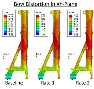
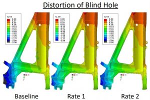
- Heat transfer rates explored in the blind hole do not contribute
to the tilting of the blind hole. - Figure 9 shows that the angle of the hole is the same, regardless of the quench rate.
- Modification of the blind hole to increase the heat transfer rate
in the hole to help improve the straightness of the blind hole is not necessary. - Heat transfer rates explored in the blind hole do not contribute significantly to the bow distortion in the XYPlane or the YZ-Plane.
- Figure 10 shows that the bow distortion is made slightly worse by increasing the heat transfer rate in the blind hole during immersion, but is not significantly worse.
- Modification of the blind hole to increase the heat transfer rate in the hole to help improve the bow distortion is not necessary.

 Structural Beam Quench Rate Sensitivity

- Reduced heat transfer of the structural arm is examined.
- Oil flow stagnancy is assumed to reduce heat transfer rate on arm.
- 2 slower heat transfer rates compared with baseline.
- Baseline assumes the same heat transfer rate on the structural arm as on the main tube OD.
- Figure to the left shows the reduced heat transfer rate surfaces of the structural arm.
- Rate 1 is slower than Baseline.
- Rate 2 is slower than Rate 1.
- Figure below shows the temperature difference in the structural beam at the end of the immersion process.
- Approximately 212°F (100°C) difference between Baseline and Rate 1
- Approximately 392°F (200°C) difference between Baseline and Rate 2
- Bow distortion in xy-plane has a non- Distortion of Blind Hole linear response to oil stagnancy around the structural beam.
- Rate 1 produced the least amount of bow in xy-plane.
- Baseline produces the greatest amount of bow in xy-plane.
- Distortion of blind hole has a non-linear response to oil stagnancy around the structural beam.
- Rate 1 produced the straightest blind hole.
- Baseline produces the greatest amount of distortion of the blind hole.
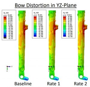
- Bow distortion in yz-plane has no sensitivity to oil stagnancy around the structural beam.
- The non-symmetric mass near the top of the landing gear has the most influence on the yz-plane bow distortion.
- Figure 15 shows lower bainite phase fraction at the end of the quenching process.

Figure 15 - Slower heat transfer rate of the structural beam results in significantly different amounts of lower bainite.
- The slower the heat transfer, the more lower bainite formed.
- Increased amounts of bainite reduce bow distortion in xy-plane, but the response is non-linear.
- Rate 2 caused slightly more distortion than Rate 1, but less distortion than the Baseline.
- Increased amounts of bainite reduce distortion of the blind hole, but the response is non-linear.
- Rate 2 caused slightly more distortion than Rate 1, but less distortion than the Baseline.

Oil Fill Rate in Main Tube Sensitivity
- The rate at which the oil fills the main tube is critical to the phase transformation timings and the phases formed.
- The immersion speed of the landing gear is 203.2 mm/sec.
- Baseline assumes the inside of the tube fills up at 20% of this value (40.64 mm/sec).
- Three different fill speeds were explored:
- 50% (101.6 mm/sec)
- 100% (203.2 mm/sec)
- 200% (406.4 mm/sec) Assumes pressure build up forces oil up the inside of the tube.
- Figure 16 compares temperature inside tube at end of immersion for four cases.

- The oil fill rate of the main tube during the immersion process has a very significant effect on all three modes of distortion.
 From top left clockwise
- Bow distortion in yz-plane has a non-linear response to the fill speed (Figure 17)
- 50% produces the worst bow
- 100% & 200% are very similar, with 200% slightly worse
- Bow distortion in xy-plane has a non-linear response to the fill speed (Figure 18)
- 50% produces the least bow
- 100% produces the worst bow
- Straightness of the blind hole has a linear response to the fill speed (Figure 19)
- Slowest fill speed has least distortion
- Fastest fill speed has the worst distortion

- Difference in lower bainite was the cause for differences in distortion with respect to oil stagnancy around the structural beam previously shown.
- Differences in distortion from the oil fill rate of the main tube are not caused by microstructural phase differences.
- Figure 18 shows that Martensite and Lower Bainite are the same for all fill speeds.
- Differences in distortion are caused by the transformation timing along the axis of the landing gear.
Immersion Direction Sensitivity

- Distortion sensitivity to the immersion direction was examined.
- Figure 19 compares temperature profile at the end of the immersion process for the two immersion directions.
- The Baseline has oil enter the blind hole first and then fill up the tube at a rate that is 20% of the immersion speed.
- Oil spills over the top of the tube and the tube is flooded with oil.
- The reversed immersion has oil enter the tube first and fills at the immersion speed.
-

Figure 20 Reversing the immersion direction also reverses the axial temperature gradient.
- Martensite transformation starts at the open tube end when the immersion direction is reversed.
- Martensite transformation starts by the blind hole first for the Baseline.
- Reversing the axial phase transformation gradient can have significant effects on bow distortion and axial displacement.
- Figure 20 shows the vertical displacement around the blind hole for the Baseline and the Reversed Immersion.
- Reversing the immersion direction had a very minor impact on the straightness of the blind hole.
- Closed side of blind hole was pulled further down by reversing the immersion direction, but the closed side

Figure 21 was not pulled up as much.
- Closed side of blind hole was pulled further down by reversing the immersion direction, but the closed side
- Figure 21 shows the bow distortion in the XY-Plane for the Baseline and the Reversed Immersion.
- Reversing the immersion direction has a significant effect on the bow distortion in the XY-Plane, nearly doubling it.
- Reversing the immersion direction has no effect on the bow distortion in the YZ-Plane.


Conclusions
- Four process parameters were evaluated for distortion sensitivities for a large landing gear component:
- Oil stagnancy inside a blind hole, oil stagnancy around a structural support beam, oil fill rate into the main tube as the landing gear is lowered into the oil tank, and immersion direction of the landing gear.
- Three distortion modes were evaluated:
- Bow distortion in XY-Plane, bow distortion in YZ-Plane, and straightness of a blind hole.
- Bow distortion in the XY-Plane IS significantly affected by oil stagnancy around structural support beam, oil fill rate up the main tube, and the immersion direction.
- Bow distortion in the XY-Plane is mainly controlled by the behavior of the structural support beam.
- Bow distortion in the XY-Plane IS NOT significantly affected by oil stagnancy in the blind hole.
- Bow distortion in the YZ-Plane IS significantly affected by oil fill rate of the main tube.
- Bow distortion in the YZ-Plane is mainly controlled by a fitting near the open end of the tube that contributes to non-symmetric mass around the main tube in that area.
- Bow distortion in the YZ-Plane IS NOT significantly affected by oil stagnancy in the blind hole, oil stagnancy around the structural support beam, or the immersion direction.
- Straightness of the blind hole IS significantly affected by oil stagnancy around structural support beam and the oil fill rate up the main tube .
- Straightness of the blind hole is mainly controlled by the structural support beam behavior.
- Straightness of the blind hole IS NOT significantly affected by oil stagnancy inside the blind hole or the immersion direction.
- Modifications to the quenching process were made to improve the distortion response of the landing gear.
- Modeling results were used to direct the modifications.
- Customer considered changes proprietary and did not share.
- Benefit of using heat treatment simulation over physical experiments to perform sensitivity studies was shown.
- Ability to modify, and see the effects of, just one process parameter with simulation is easy.
- Ability to modify, and see the effects of, just one process parameter with experiments is very difficult, if not impossible.
- Cost of simulation is minimal.
- Cost of physical experiments can be very high.
Text developed from powerpoint version. Click here to view or for more information on DANTE case studies.