General Atomics has heat treated the seventh and final module for a large superconducting magnet for ITER, a multi-national science experiment, with a vacuum furnace from a heat treat furnace supplier in Pennsylvania.
In order to convert the 6 km long stainless-steel-jacketed coil of Niobium-Tin conductors into superconductors for the ITER (International Thermonuclear Experimental Reactor) experiment, each of these 4-meter by 2-meter 110-ton solenoid sections had to be heat treated for five weeks, exceeding 650°C (1202°F) at its peak. The heat treatment served to alloy the Niobium and Tin strands together into Nb3Sn, which becomes a superconductor when chilled with liquid helium to 4 Kelvin.
No such heat-treating furnaces existed, so General Atomics turned to SECO/VACUUM, a SECO/WARWICK Group company in Meadville, PA, to build a heat-treating furnace large enough to fit these solenoids and packed with all the technology needed to meet the strict quality control standards of this experiment.
Peter Zawistowski Managing Director SECO/VACUUM TECHNOLOGIES, USA Source: secowarwick.com
"SECO/WARWICK Group did a great job designing in backup systems and robust design," commented Nikolai Norausky, program manager at General Atomics. "Any time we had questions or needed maintenance they were there to help."
The vacuum furnace that the supplier provided had to perform multiple tasks, including to bake off residual impurities from coil fabrication and to anneal internal stresses introduced at different stages of part fabrication. “General Atomics put so much time and money into these coils we really didn’t have any room for error," added Peter Zawistowski, managing director of SECO/VACUUM, "so nearly every component had to be doubly redundant."
Explore the experiment in Heat Treat Today original content article.
Find heat treating products and services when you search on Heat Treat Buyers Guide.com
Imagine this: A huge lab facility nestled in the south of France . . . teams of scientists and technicians striving to bring carbon-free energy solutions to the world . . . “replicating the high-energy fusion reaction that powers the sun and stars.” To complete the project, what heat treat solution is needed? Read more in thisTechnical Tuesday to find out.
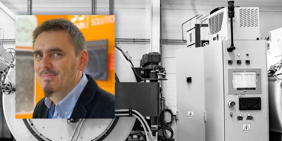
This article by Rafal Walczak,product manager at SECO/VACUUM, will be published in Heat Treat Today’s December 2022 Medical & Energy print edition.
Introduction
For this case study, we will discuss how SECO/VACUUM built a highly specialized custom heat treating furnace used in the construction of the central component of a large, multinational science experiment.
The Experiment
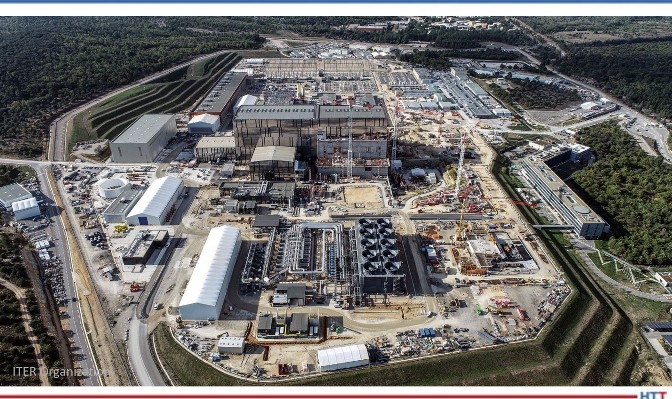
ITER (standing for International Thermonuclear Experimental Reactor and meaning “the way” in Latin) is the largest high-energy science experiment ever conducted. At a giant lab facility in southern France 35 countries, hundreds of vendors, and thousands of scientists and technicians are collaborating on a device to demonstrate the feasibility of clean, safe, carbon-free energy production by replicating the high-energy fusion reaction that powers the sun and stars.
Figure 1. ITER Laboratory at the Cadarache research center in southern France Source: ITER Organization
There are no solid materials that can touch, much less contain, such a high-energy reaction without immediately vaporizing. Instead, this super-hot cloud of plasma must be contained by a special configuration of magnets called a tokamak, which can trap charged particles in a toroidal or donut-shape cloud. This tokamak has 10 times more plasma containment volume than any other tokamak ever built.
The term “tokamak” comes to us from a Russian acronym that stands for “toroidal chamber with magnetic coils” (тороидальная камера с магнитными катушками).
The Magnet
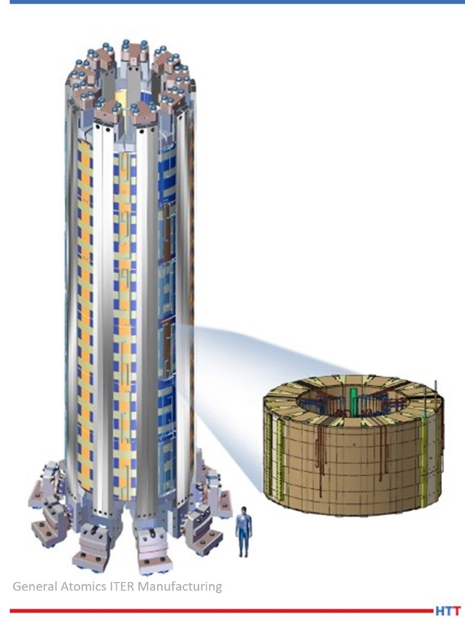
Figure 2. ITER central solenoid and one isolated solenoid module Source: General Atomics ITER Manufacturing
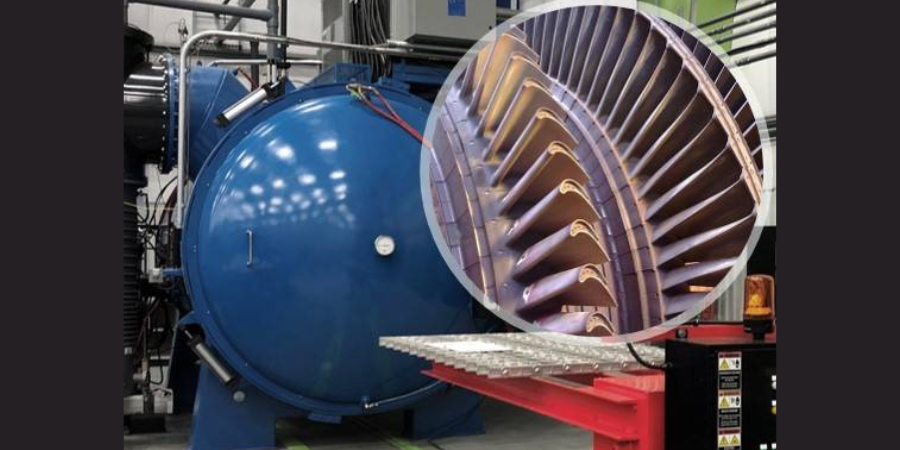
General Atomics’ Magnet Technologies Center near San Diego, CA was contracted to build the ITER tokamak’s large central magnet, the most powerful superconducting magnet ever built, strong enough to lift an aircraft carrier. Other magnets in the tokamak serve to contain the plasma. The central solenoid is an oscillating magnet responsible for inducing current in the plasma cloud similar to how an induction stove heats a pan, except it is heating the plasma to 15 times the temperature of the surface of the sun. Far too large to be constructed and transported in one piece, the 12-meter-tall, 4-meter-wide coil of wires must be built in six 2-meter-tall modules to be joined once they are all on site at the lab. A seventh module will be built as a spare.
Kenneth Khumthong, technical lead for final testing and fabrication certification for ITER Central Solenoid at GA, described the tests on each module of the magnet, saying, “We run a battery of tests on each and every module subjecting them to voltages as high as 30,000 volts and powering them with as much current as 40,000 amps. This is done to ensure that every module meets all of ITER’s specifications prior to shipping them out to France.”
Embrittlement vs. Field Strength Tradeoff
Other superconducting electromagnets in the ITER tokamak will be made using coils of relatively durable niobium-titanium alloy. Past experiments have demonstrated that magnetic fields greater than 12 Tesla disrupt the superconducting properties of Nb3Ti. The ITER central solenoid, however, must sustain magnetic field strengths above 13 Tesla. For this reason, the central solenoid coils must instead use niobium-tin as its superconducting wire, which more reliably maintains superconducting properties in such high magnetic fields but is also more brittle and too fragile to bend after reaction to Nb3Sn. In order to accommodate for the brittle wire, General Atomics had to first coil the wire and jacket into their final shape before heat treating the metals into their superconducting, albeit brittle, alloy Nb3Sn.
The Wire
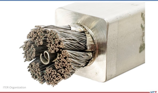
Figure 3. A dissection of the central solenoid conductor strands, central spiral, and structural jacket Source: ITER Organization
Niobium-tin wire strands react to become Nb3
Copper strands serve as traditional conductors to safely dissipate stored energy when the superconductivity experiences a disruption. The copper strands do not react with the niobium-tin.
A central spiral maintains a hollow channel to circulate liquid helium to chill the Nb3Sn wires to 4°K, below their superconducting temperature of 12°
Creating such strong magnetic fields inside a coil of wire will also tear apart the coil of wire itself if that wire is not supported inside a high strength jacket. The ITER central solenoid wire bundle is about 38.5 mm diameter, housed inside a 50 x 50 mm stainless steel jacket.
Total maximum current in the superconductor wire is 48,000 amps.
Worldwide niobium production increased six-fold for several years just to meet the niobium demands of the ITER project.
The Heat Treating Furnace
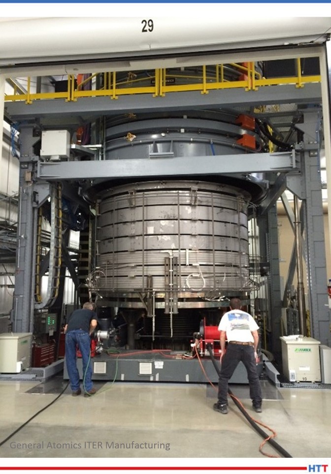
Figure 4. Technicians ensure proper placement before lowering heat treat furnace Source: General Atomics ITER Manufacturing
In order to convert the niobium-tin metal conductors into superconductors, each of these 4 meter by 2 meter 110 ton solenoid sections must be heat treated for five weeks, exceeding 1200°F (650°C) at its peak. The heat treatment serves to alloy the niobium and tin together into Nb3Sn, which becomes a superconductor when chilled with liquid helium to 4°Kelvin. No such heat treating furnaces existed, so General Atomics turned to SECO/VACUUM to build a custom heat treating furnace large enough to fit these solenoids and packed with all the technology needed to meet the strict quality control standards of this monumental experiment.
Five inch wide metal band heaters ring around the walls of the furnace with nearly 900kW of heating power. Covering 50% of the walls, they provide a very uniform heat. This is brought about by the following seven steps.
The Heat Treating Sequence
In addition to alloying the niobium-tin wires, the furnace also serves to remove the stresses in the stainless steel jacket housing the superconducting wire and to bake off any residual contaminants prior to reaching reaction temperature.
1. Complete a quality control test: Vacuum seal the untreated solenoid coil in the room temperature furnace and charge the inside of the conductor jacket with 30 bar high pressure helium to test for leaks after forming and welding.
Monitor furnace atmosphere with ultra-high sensitivity mass-spectrometer helium detectors.
2. Purge with argon gas while slowly ramping up heat.
This drives off hydrocarbons and oxygen before system reaches reaction temperatures.
Monitor furnace atmosphere with gas chromatograph to find impurities from residual oils and lubricants leftover from manufacturing process.
Monitor and control argon circulation and exchange with mass flow sensors and circulation blowers that penetrate the furnace lid with ferrofluidic feedthrough seals around the blower motor shafts.
3. Maintain at 1058°F (570°C) for about 10 days. Confirm stabilized temperature and pure atmosphere.
4. Proceed to 1202°F (650°C) for four days. This is the actual reaction phase that achieves the primary objective of converting the niobium-tin into the superconducting alloy Nb3
5. Very slowly and uniformly ramp back down to room temperature to avoid additional stresses in the coil.
6. Complete another quality control test: Evacuate the argon and once again vacuum seal the solenoid coil in the room temperature furnace and recharge with 30 bar high pressure helium to test for leaks after heat treating. Monitor atmosphere for the presence of helium, which would indicate a leak in the coil.
7. Only then is it ready for the post-heat treating stages of wrapping with insulation and encasing in epoxy resin for rigidity.
Options, Upgrades, Special Features
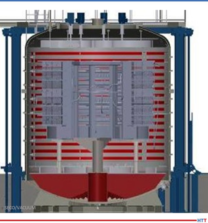
Figure 5. Cutaway illustration showing the furnace construction Source: SECO/VACUUM
There was no room for error. SECO/VACUUM collaborated with the engineers at General Atomic to create a heat treat furnace that can assure temperature variation within the coil never varies by more than 18°F (10°C) anywhere in the furnace at any time in the five-week cycle and achieves near-perfect repeatability for all seven modules.
They accomplished this with quadruple-redundant control thermocouples and feeding temperature data from 150 points in the coil into the control computers. To shield against impurities, the furnace is first evacuated to a vacuum pressure of 0.001 Torr, and then purged with pure argon to drive out any residual oxygen or hydrocarbons that could contaminate the purity of the superconductor. Monitoring the argon atmosphere for impurities are redundant mass spectrometers. The argon is circulated by seven convection fans to heat the solenoid assembly evenly. Each of these fans must be driven through ferrofluidic feedthrough seals which allow the rotating shafts to operate through the furnace walls without compromising the vacuum seal of the furnace.
Consult, Collaborate, and Partner with SECO/VISORY
General Atomics first began discussing this project with Rafał Walczak, the product manager at SECO/VACUUM, in early 2010. Both teams spent over two years on conceptual discussions, preliminary designs, and process simulations before SECO was even awarded the contract. Once SECO was on board, it took another two years of design, fabrication, and installation before the furnace could be put into operation. SECO/VACUUM built it to handle a lifetime of use without error so they could be sure that it would work flawlessly for the seven cycles that it actually had to run.
The SECO/VISORY Heat Treat Advisory Council is a team of SECO/VACUUM heat treat experts and consultants with diverse thermal experience and process knowledge who are available to help companies solve their specific heat treat equipment challenges.
About the Author: Rafal Walczak is the product manager at SECO/VACUUM. Rafal joined SECO/WARWICK Group as a service engineer in Vacuum Furnaces Division soon after graduation from Technical University of Zielona Góra in 2002. Since 2008, he has been involved in vacuum furnace sales in Europe and the USA. The combination of his technical background and field service experience help him provide outstanding support to his SECO/VACUUM customers. For more information, contact Rafal at Rafal.Walczak@SecoVacUSA.com.
Find heat treating products and services when you search on Heat Treat Buyers Guide.com
Sometimes our editors find items that are not exactly "heat treat" but do deal with interesting developments in one of our key markets: aerospace, automotive, medical, energy, or general manufacturing. To celebrate getting to the “fringe” of the weekend, Heat TreatToday presents today’s Heat Treat Fringe Friday press release about how BCI Steel and Nextracker LLC are using new and reshored equipment to produce solar tracker equipment.
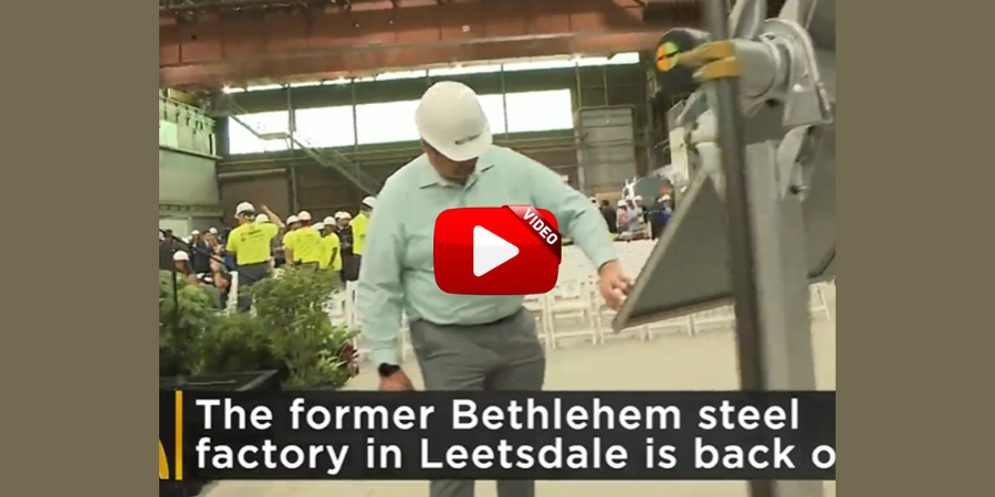
Nextracker LLC, a provider of utility-scale solar trackers, and BCI Steel, a Pittsburgh-based steel fabricator, announced the reopening of the historic Bethlehem steel manufacturing factory in nearby Leetsdale to produce solar tracker equipment for large-scale solar power plants.
The steel processing plant will incorporate both BCI Steel’s new and reshored equipment shipped to the U.S. from factories in Malaysia and Brazil. Solar tracker products produced at the factory will serve rapidly growing solar markets in Pennsylvania, Indiana, New York, and Ohio.
“BCI is proud to advance Pittsburgh’s legacy as the heart of America’s steel industry,” said Matt Carroll, CEO of BCI Steel. “This partnership with Nextracker showcases . . . unlocks additional domestic solar capacity with our low-cost manufacturing.”
This is the third solar tracker fabrication line Nextracker has commissioned with a steel manufacturing partner in 2022 as part of its commitment to rebuilding America’s steel and solar supply chains. With additional capacity in Pittsburgh, Nextracker is building out 10 GW of “Made in America” manufacturing capacity — enough to power 7.5 million homes. Earlier this year, Nextracker opened a green steel tracker production line in Texas with JM Steel, and another dedicated steel production line in Arizona with Atkore. Under this reshoring initiative, Nextracker has already procured over 100,000 tons of U.S.-made steel so far this year, enough for approximately 5 GW of solar trackers.
"This investment," commented Dan Shugar, CEO and founder of Nextracker, "will increase the resilience of the U.S. solar supply chain and bring manufacturing jobs, equipment, and capacity back to America."
The newly reopened Pittsburgh factory is situated with close proximity to river and rail transport in a location steeped in manufacturing history. The factory lies on the same grounds where steel fabricators built materials for tank landing ships (LSTs) during WWII.
The dedication ceremony was attended by top dignitaries and leaders from some of the world’s largest clean energy companies, including the CEO of EDPR Sandhya Ganapathy and the Chief Operating Officer of Lightsource bp Ann Davies.
A global leader in power technologies purchased a vacuum furnace from a North American furnace provider. The equipment will be used for specialized nuclear operations.
Peter Zawistowski Managing Director SECO/VACUUM TECHNOLOGIES, USA Source: secowarwick.com
SECO/VACUUM, a SECO/WARWICK Group company, was awarded the order for the 2-bar Vector®, a single chamber high-pressure quench vacuum furnace. It will be used for a variety of heat treating processes, including hardening of tool steels as well as high vacuum sintering and annealing. The furnace design will achieve deep vacuum levels, allowing the customer to process materials for nuclear applications. The new Vector will replace an older furnace, adding significantly more capabilities and process flexibility.
"I’m very proud of how our SECO/VISORY group managed this relationship," noted Peter Zawistowski, managing director of SECO/VACUUM. "Our product management and engineering staff collaborated with the customer’s engineering and commercialization teams for over a year to develop a proposal for the specialized capabilities they required."
Find heat treating products and services when you search on Heat Treat Buyers Guide.com
Marcin Stokłosa Project Manager Nitrex Poland LinkedIn.com
A global aluminum and energy company, Hydro Extrusion Norway, recently received a horizontal nitriding system, configured to replace an old decommissioned furnace
This latest delivery by Nitrex is the only one of its kind at Hydro facilities globally; the rest are pit-type furnaces. The nitriding equipment for Hydro Extrusion Norway in Magnor, Norway will integrate with the existing infrastructure of the plant as well as fit in the specific floor space allocation.
"Before placing the order, Hydro did its due diligence – visiting extrusion facilities with Nitrex equipment to get user opinions on the solution including the technology, die performance, extruded profile quality, and our support services," adds Marcin Stokłosa, project manager at Nitrex. "Moreover, the test trials produced very good results."
NexGen Advanced Fuel Systems (AFS), a gas turbine component overhaul facility that is a company of Allied Power Group, ordered a new vacuum furnace to help increase their capacity and reduce turnaround time for their heat treating and brazing operations. It is built specifically to heat treat land-based turbine equipment with attention to specific cooling specifications required by the company's clients.
Built by Solar Manufacturing, the furnace features a Solarvac® Polaris Control System and a graphite hot zone accommodating loads up to 48" wide x 48" high x 72" deep. The furnace has a maximum load weight capacity of 6,000 pounds.
The furnace achieves a vacuum level of 10-5 Torr, and reaches a maximum operating temperature of 2400°F. A 300 HP gas fan will allow NexGen to quench a load from 2150°F to 1000°F in just three minutes, using only 2-bar.
Solar Manufacturing Vacuum Furnace Source: Solar Manufacturing
"The interface makes running the furnace easy for operators of all skill levels," states Mark Dion, president of Nexgen-AFS, and the general manager ofAllied Power Group Combustion Technologies. "For furnace installation and operation, Solar provides knowledgeable engineering and support staff. The Solar furnace has a robust design, with some nuances such as stainless steel internals, brass fittings, made in USA valving, and in our case, a beefed up blower allowing super-fast cooling abilities. . . . Nexgen hopes business growth supports purchasing a second Solar vacuum furnace."
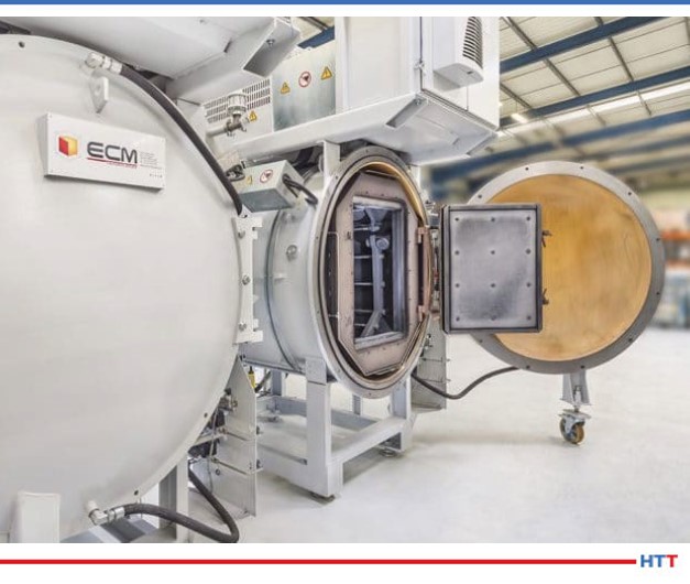
An automotive supplier and a hydraulic pump manufacturer will acquire multi-chamber vacuum furnace system for low pressure carburizing.
For the automotive supplier of innovative driveline solutions, the system is estimated to reduce CO2 emissions significantly for vacuum carburizing versus an existing atmosphere carburizing furnace. For the hydraulic pump manufacturer, the modular flexibility of this specific furnace was the most important advantage.
ECM Flex Multi-Chamber System Source: ECM USA, Inc.
The supplier, ECM USA, Inc., notes that their Flex Multi-Chamber System is built as a standard system with the possibility to further expand its capacity and/or to upgrade to a high level of automation (robots, AGVs, vision systems, or other 4.0 elements). In addition to modularity, several processes can be handled in the Flex furnace, such as: low pressure carburizing (LPC), vacuum tempering and a combination of vacuum sintering followed by hardening.
This stems from advanced automation technology -- including robotics -- acting as driving forces behind increased use of more eco-friendly applications outside the LPC-HPGQ sector. This includes, but is not limited to, multiple tool steel processing systems, brazing applications, and rapid thermal processing (RTP) systems.
Here is what readers are saying about recent posts on Heat Treat Today. Submit your comments to editor@heattreattoday.com.
Hello Heat Treat Daily,
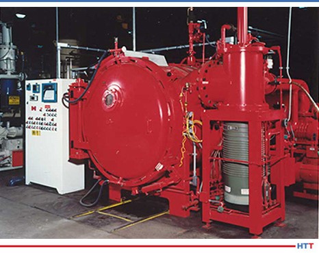
I was surprised to see this bright red furnace on your daily email this past Friday. This is an old image of a furnace still in production at my company Spectrum Thermal Processing in Cranston, RI.
Now, like most of us, this furnace is showing some age, but is is still in production every day with an upgraded control panel and SSI controls.
I reflected on this particular email and want to add that what I find intriguing about heat treat is the longevity of some of the equipment. This furnace processes work for aerospace, automotive, commercial cutting tools and oil and gas refinery and has for nearly 30 years! Just to the left of this furnace in the photo is an older single chamber vacuum furnace that has process parts for the Apollo space program and has recently processed parts for SpaceX. Somehow this equipment just keeps going.
Thanks for your daily insight into the heat treating industry.
Rick Houghton
VP of Operations/Quality Manager
Spectrum Thermal Processing
We welcome your inquiries to and feedback on Heat TreatToday articles. Submit your questions/comments to editor@heattreattoday.com.
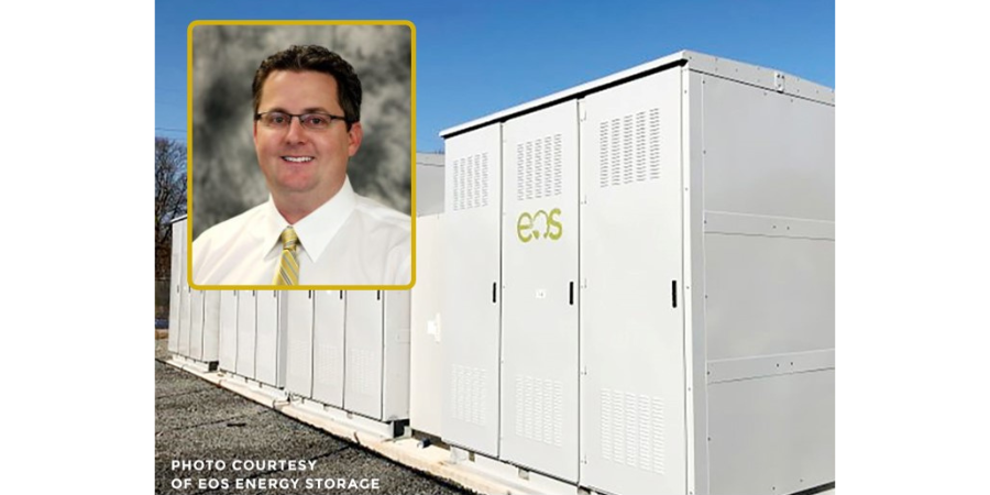
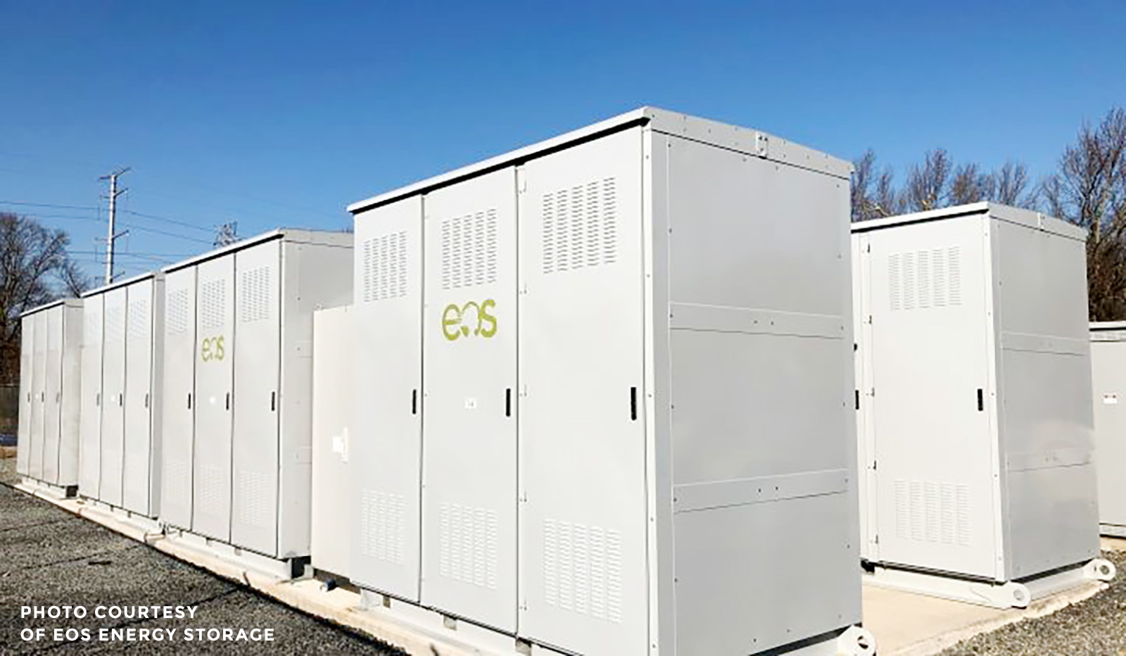
The energy storage company HI-POWER, a Holtec International and Eos Energy Storage joint venture, recently formed a five-year partnering agreement with a North American heat treat supplier to provide an energy efficient non-lithium, long duration energy storage solution using battery technology.
The new battery technology, a decade in the making, is an efficient non-lithium, long duration energy storage solution. One of the critical components within the battery system requires a “vacuum cathodic” heat treatment process. This newly developed surface heat treatment process enables the product to last 5,000 cycles for a 15-year calendar life with no subcooling or pumps required.
HI-POWER and Solar Atmospheres of Western PA engineers worked to develop the vacuum cathodic heat treatment needed to fulfill HI-POWER’s specifications. Today, Solar is thermally processing thousands of components to help HI-POWER deliver clean and reliable energy faster for the world’s needs.
"I came upon this opportunity at a trade show four years ago," said Mike Johnson, sales manager for Solar, "At that time, HI-POWER was perfecting their critical thermal cycle profiles in a small hot wall furnace in New Jersey. HI-POWER knew that someday they would need to employ a large vacuum furnace - and we had that capability."
HI-POWER builds one of the safest and fully integrated DC storage batteries in the world. Their “Znyth” storage batteries are especially stable when housed in extreme temperatures and are nonflammable and 100% recyclable.
(photo source: Solar Atmospheres, courtesy of EOS Energy Storage)
Heat TreatRadio host Doug Glenn talks with Joe Powell of Integrated Heat Treating Solutions in this third of a four episode series about bringing heat treating into the 21st century. This episode covers the fascinating heat treatment of a fracking pump valve seat.
Below, you can either listen to the podcast by clicking on the audio play button, or you can read an edited version of the transcript.
The following transcript has been edited for your reading enjoyment.
Doug Glenn (DG): We're continuing our conversation with Joe Powell of Integrated Heat Treating Solutions. on rethinking heat treating. I strongly recommend that you listen to parts 1 and 2 of this series as well as today's episode. All three are fascinating. To hear the first two parts, click here.
Today, we’ll be talking about what I think, if you've listened to the first two episodes of this four part series, is a very fascinating, I think, somewhat revolutionary advancement in heat treat.
Today, basically what we want to talk about is a really interesting example of the general concept of what we talked about in session one. I want to review that first session very briefly and ask you a couple of other quick questions before we jump into the example of a fracking pump valve seat, which is where we're headed today. But first, maybe from a 30,000-foot view, Joe, tell us what we're talking about here. If you were to put this in a minute, how would you describe what it is you've been doing over at Integrated Heat Treating Solutions?
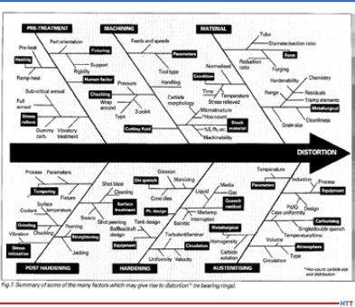
Joe Powell (JP): Integrated Heat Treating Solutions (IHTS) is a consultancy that takes 75 years of practical commercial heat treating and applies it to help part-makers make better parts by using heat treating knowledge. We also work with the material-makers who want to get more added value out of a given hardenability material. What IHTS is essentially doing is taking off from the idea that quenching causes the most problems in heating: it causes distortion, part cracking and size change that is unpredictable. That distortion engineering has been part of the ASM and other societies that have had task forces, committees, and various conferences that are dedicated to the control of distortion.
Potential factors influencing distortion (Source: American Gear Manufacturers Association, sourced by Joe Powell)
The reality is that the control of distortion has been approached by many, many people, including Dr. George Tautin, who was one of the inventors of the reverse solubility polymers when he worked for Dow Chemical and Union Carbide, and Dr. Kovosko in the former Soviet Union, who was my partner in IQ Technologies starting back in 1999. What we've discovered working with all of these very smart people is that the quench cooling rate and its relationship to causing part distortion or part cracking is a bell shape curve. In other words, if you quench very slowly in air or gas or hot oil or martemper salts, hot salts for austempering, you will not crack the part. But, if you quench faster in brine, water, or even water polymer mixtures that don't have enough polymer in them to act like an oil quench, the cooling rate will become relatively fast. That relatively fast cooling rate will give you a much higher probability of part cracking, until on some parts you'll literally crack every part you put in the quench if it's quenched in water.
If you can create a shell on the outside of the part and quench it 752°-1112° F (400°- 600° C) per second, that shell will literally hold that hot part while the hot core thermally shrinks underneath and pulls that shell under compression. As that thermally cooling shell and hardened shell of martensite goes through volume change and actually increases in volume, the grains are actually pushed up against each other under compressive surface stresses, and that compressive surface stress holds the part like a die. So, regardless of its geometry or mass, that part is going to come out of the quench having cooled by uniform conduction down to its core through that shell in a very predictable shape.
DG: That's exactly what I wanted to get to: what we're talking about here is a quenching issue. It's quenching parts fast enough so that, in a sense, what you're doing is creating a hard outer, immovable shell, if you will, pretty much instantaneously, which holds that part in place while the core cools down to the temperature that is needed.
The quenching media, in one sense, don't really matter. It can be done. The issue is getting that shell formed quickly, uniformly and then holding it at a certain temperature until the core cools.
You and I have spoken in the past, Joe, about a kind of interesting quote which I'd like you to comment on before we get to the fracking pump valve seat example of what we're talking about. Here’s the quote I'd like you to address, “Everyone knows how to heat treat. All you need is a torch and a bucket of water.”
"Every day I learn that in the 23 years that I've been working on heat treat quenching and focusing on that and controlling of distortion, there is always something new, and there is always something new in the field of, what I call, metallophysics."
JP: That's correct. Every machinist you'll ever meet, and even a machining handbook, will tell you how to heat treat a part, and do it quick and dirty. The problem is everybody thinks that it’s because they've heat treated a part in the past, that they know a lot about heat treating, and that is just not the case. There is so much to know, that all I can tell you is that every day I learn something new. Every day I learn that in the 23 years that I've been working on heat treat quenching and focusing on that and controlling of distortion, there is always something new, and there is always something new in the field of, what I call, metallophysics.
DG: Right. It brings me back to a couple of thoughts along that line. One, it's the whole idea that “a little knowledge is a dangerous thing” – we think we know and yet, we don't. You've told me a story in the past and I think it's worth our listeners hearing it, and that is just an abbreviated version of the Jack Wallace story. Again, Jack Wallace, the head heat treat metallurgical guru at Case Western Reserve University, comes into your shop and you tell him, “I can quench these things so super-fast,” and he looks at you and says, “You are a crazy man. It's not possible.”
JP: Actually, it was worse than that. Dr. Michael Aerinoff came from Russia and was telling Jack about this technology that Dr. Kovosko discovered back in the former Soviet Union. So, it had two strikes against it. Not only was it new information and contrary to the idea that the faster you quench, the more likely you are to blow up the part, but it was also contrary to the information, “Hey, we're in the United States. We know all about heat treating and metallurgy!” At the end of the day, this metallophysics twist that Dr. Kovosko put on the dynamics of the heating and cooling process is really the key to understanding and viewing metallurgy from another dimension – the dimension of residual and current compressive stresses that are affecting the part. That's what Dr. Kovosko told us about, and finally, that's what unlocked the ability of the parts that Professor Wallace witnessed being quenched and not cracking.
DG: I would have loved to have been there and seen the eyebrows of Dr. Wallace.
JP: The other two metallurgists who were in the room besides me – two owners of heat treating companies, Wayne Samuelson of Shore Metal Treating at that time and John Vanas at Euclid Heat Treating – both of them basically wrote Michael off as a crackpot because they had heard what professor Wallace had said. I was the only one dumb enough to think, “Well, come on down. If you want to demonstrate some parts, they're either going to blow up or they're not. If they don't blow up, it'll be interesting, and if they do blow up, it will be funny, so let's try it!”
DG I wanted our listeners to hear some of the other people who are now, as I say in quotes “true believers.” You've got Jack Wallace who now believes what you say is actually true. You've also got, I believe, George Tautin, who is kind of the “king of quench.”
JP: Absolutely. He's actually written a book with us. It's an ASTM book; it's publication #64, I believe, and that book tells you exactly how to build the first and second generations of IQ (intensive quenching) equipment. George also said in 2014, after he retired from making polymer quenches, that you don't really need oils or polymer quenches. You can do quenching very nicely with a properly designed quenching system and water, or water and a little bit of salt. That was a pretty strong statement from a guy who literally spent his career making those quenches better.
DG: You had mentioned one other individual, Robert O'Rourke.
JP: Yes, he is a metallurgist with over 30 years of experience with ductile iron. Bob worked with one of the industry giants, Chip Keough,* who founded Applied Process and also austempered ductile iron. Chip's company not only worked with the ductile iron society for many years, but also with Bob O'Rourke, who was one of the principals at the Ductile Iron Society; in fact, he was president back in 2015. At the end of the day, he basically said that we could take this kind of crappy material, ductile iron, and austemper it. Chip made a very good business out of austempering ductile iron at Applied Process and converted many, many parts from either as-cast ductile or even steel parts to austempered ductile iron parts.
That, to me, showed that it's possible to take a heat treating process and apply it to a material and literally create a new material out of as-cast ductile irons. Chip even said, “I know what you guys are doing. When we quench in salt, it's very uniform. There is no film boiling. There is no nonuniformity in the cooling. All you're doing is just kicking it up a notch with higher intensity and knocking off the film boiling with the intensive agitation.” And I said, “You're absolutely right, Chip.” What we did not know at that time was that it could be applied to ductile iron.
DG: Let's jump into this fracking pump valve seat. A couple basic questions. First off, we're talking about a pump that is used in the fracking industry to extract out, I assume, the fracking fluids, and things of that sort.
JP: It's actually to inject the high-pressure water sand. They call the sand a proppant. After the pump has fractured the shale layers, then they inject water and sand to hold up and prop up those cracks in the geology and allow the gas to flow out more quickly.
DG: Good. So, the point is, it is very rugged and the pump takes a beating. What was the problem that the company was having? How did it come to your attention?
JP: The frackers were having to rebuild the pumps every 40-60 hours and replace these valve seats. They had high pressure water and sand flowing through the valves. The valve would open and close under pressure at about four times a second, and that constant abrasion of the valve opening and closing and banging into the seat was causing the seat to wear out. Once the seat is worn, then the pump can't maintain its pressure, and they're not getting anywhere in terms of putting that fluid down in that well, and therefore, making it produce more oil and gas products.
DG: Essentially, you've got fracking companies who are having to replace valve seats and rebuild the valves every 40-60 hours. What was the material that was being used for the valve seat?
JP: For years, these types of seats were made of 8620 carburized steel. They usually start with a forged ring, and then they machine that ring into a valve seat with a taper and a strike face where the valve closes onto the valve seat. That part is generally carburized around 90,000th of an inch effective case step and tempered and then put into the pumps. Again, that case hardened surface is 60–65 Rockwell and wears very, very well and resists the abrasion of the sand and water. Because it's 8620, it has a ductile core underneath the strike face that absorbs the impact of the valve opening and closing on top of it every four seconds under pressure.
You have to have a combination of hard, yet ductile. And you have to have a tough part that resists wear and abrasion.
DG: These guys were using it and still having to replace it every 40-60 hours, so what was your thinking on it and how did you guys help?
JP: A whole bunch of people had tried to put tungsten carbide inserts into the strike face to make the strike face even harder than case hardened material. Then a company came out with a solid sintered tungsten carbide valve seat that costs upward of $500–800 each. You’ve got to remember that there are ten of them in the pump, and they were built as a lifetime valve seat because they actually outlasted the pump block and some of the other parts of the pump. But that was not a great solution because, at that point, you have a seat that's lasting longer than the pump block. You still had to take apart the pump anyway for other things that were worn; it's too good and it's too expensive. If you've got $8,000 worth of seats, you're not going to throw the pump block out because it's worn out, you're going to try to remove those seats.
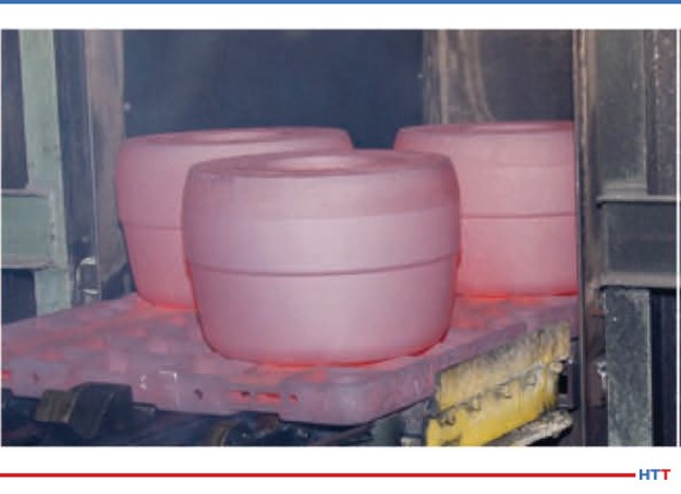
Large Rolls on Their Way into IQ Tank (Source: Joe Powell)
Again, what they were looking for was a longer life valve seat, not necessarily a lifetime valve seat, but something that would last for all of the stages used by that pump at a certain well. They would move it at the time that the well completely fracked and started to produce and take it back and rebuild it at their shop. They were shooting for 200 hours.
DG: Right. Again, the normal was 40-60 hours with the 8620 material.
JP: Right. Having had the experience with the elongator roll and the ability to make something that was literally so hard they couldn't knurl it, we had to temper those elongator rolls back quite a bit in order for them to knurl them and then use them at the mill. I thought, if we don't temper the valve seat back and just leave it that hard, it should be carbide-like hard, because if a carbide tool can't knurl it, it's pretty doggone hard. We fired up our existing piece of equipment that we had at Akron Steel Treating, a 6,000-gallon intensive quenching tank. We heated the parts and quenched them in that big batch tank, and we got very nonuniform results.
One of the things we did not understand back in 2012 was that ductile iron, because of all the graphite particles that are in there, has a very low thermal diffusivity, meaning that in order to get the heat into it or out of it during the quench, you had to be more than intensive; you had to be, what I call, instantaneously impacting that surface with high pressure water that literally pulls the heat out at a rate that will allow you to get to the martensite start temperature, cool to the martensite start temperature, and form that shell in less than 2/10th of a second – and you have to do that all over the part surface to create that shell. This required the making of some new induction heating equipment that have an integrated quench system built into it. This integrated quench system is going way past the ability of our 6,000-gallon tank with its propellers flowing the water laminally across the surface and literally impacting the part instantaneously after the induction heat is turned off.
DG: I want to mention to the listeners that we'll put a photo of this part in the transcript that we'll have on the website so that they can get a much better sense of what the part is; there are some lips and turns and there is an inside diameter and an outside diameter. As you say, if you're flowing water laminally over this, you're going to be missing parts and you're going to be missing areas of the part, so you need to get it quenched quickly.
JP: They actually did crack in the O-ring groove and under the flange out of our 6,000-gallon tank, so we knew we had to do something different. The first thing we tried was to put in the flange and the O-ring groove after it was heat treated, but that wasn't going to work because the part-maker didn't want to have to machine it twice. We had to come up with a way of delivering that water all over the shell of that part and also keeping the core relatively ductile. We didn't want to harden it all the way through and make it brittle, so that's what we came up with while working with the folks at Induction Tooling in North Royalton.
DG: So, it was basically an induction heat and an integral induction quench, very high impact, instantaneous, probably way beyond what anybody else has seen. Describe very briefly, what kind of horsepower was needed to go into the quench.
JP: We used a 60 gallon/minute pump for the ID and a 60 gallon/minute pump on the OD. Both pumps were operating at 60 psi, so there is quite a bit of pressure and quite a bit of flow over a very, very small area.
DG: Which is exactly what needed to be done. So, talk about the results. You're hinting at them here, but what are we talking about in regards to Rockwell hardness and that type of stuff?
JP: We're getting 60+ Rockwell hardness. Again, you've got to remember that this is an apparent hardness because the Rockwell machine is fooled by the very soft graphite particles that are in the matrix. You have very, very hard martensitic iron and carbon in the surface, but you also have these little particles of spherical graphite, and that graphite acts as, what we believe, a lubricant. We haven't quantified it in the valve seat, but we've quantified it for some dies that gives lubricity that's not present in a steel part. The graphite lubricates whatever is traveling over the surface of the part. The other thing that we learned is that the compressive residual surface stresses, when tested by x-ray defraction, are about double that you get when you do carburization of the 8620 valve seat. The very high residual compressive surface stresses also hold those grains of iron carbides in place and does not allow them to abrade or erode. In the first testing, we had three seats that went out to the field somewhere in west Texas, and they lasted 166 hours. We were almost there.
So, we've modified the quenching system, we've modified our heating recipe on the induction tooling, and we made another set of valve seats which we are currently sending out for more field testing. We hope we're there and we'll see what happens. But we literally created a new material. The history of ductile iron goes from as-cast to austempered ductile iron and now, what we call, instantly quenched ductile iron or IQDI
DG: Nice. It all sounds very, very interesting, but I can see some people listening to this saying, “Ok, how much is this going to save me?” Let's talk about the ways that this process saves money. In my mind, you've got a shorter processing cycle time, you're using less expensive material, and you're getting a longer life. Are those the three major ones?
"With the valve seat, the forging and the 20 hour carburizing cycle are eliminated, and it’s machined three times faster. One customer let slip that they were saving about 66% on the material cost."
JP: There is also one other and that is ductile iron because those graphite particles machines about three times faster than steel. So your through-put in your CNC machine goes up by 2 or 3 times when you're making the part and that is no small matter. Also, because the quench is so impactful and so uniformly impactful, it sets the part and you literally get a part that quenches to fit. Once the green size before heat treating is adjusted, the part may not need much, or if any, final grinding.
DG: So, you're saving on post heat treat processing, as well.
JP: Right. And, because we use no oil, we don't have to wash the parts and we don't have to worry about disposing of quench oils or about quench oil fires. And, the process can be done in the machining cell, so it's an in-line process versus a batch carburizing process that has to go someplace for 20 hours to be carburized.
DG: Significant. I think you threw out a dollar figure when we spoke about this previously. What are the savings per valve seat?
JP: With the valve seat, the forging and the 20 hour carburizing cycle are eliminated, and it’s machined three times faster. One customer let slip that they were saving about 66% on the material cost.
DG: Wow. Significant cost savings is the point, so something worth looking into. We're going to have one more episode where we talk about another example. What do you think we'll talk about in the last episode?
JP: The integration of heat treating into the forging process.
DG: Alright super. Thanks for being with us, Joe. It’s always interesting and intriguing.
JP: The integration of heat treating into the forging process. The forging industry association sponsored a project with IQ Technologies. Akron Steel Treating is a member of the forging industry technical committee and has been for years, and we've always thought that there should be a closer alliance between forgers and their heat treaters. We're going to take the information that we gained from this 4 year project, the published final report will be on our website, and we're going to try to commercialize that for a lot of different parts.


 General Atomics has heat treated the seventh and final module for a large superconducting magnet for ITER, a multi-national science experiment, with a vacuum furnace from a heat treat furnace supplier in Pennsylvania.
 Find heat treating products and services when you search on Heat Treat Buyers Guide.com