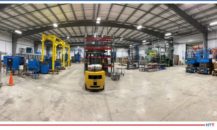
Peters’ Heat Treating, Inc., a 40-year-old heat treating company that specializes in a variety of high tech heat treating processes, moved its headquarters into a newly expanded Meadville, Pennsylvania facility located in the western part of the state.
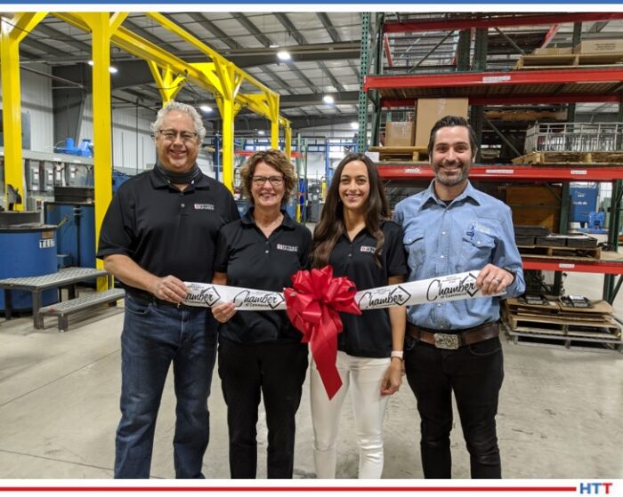
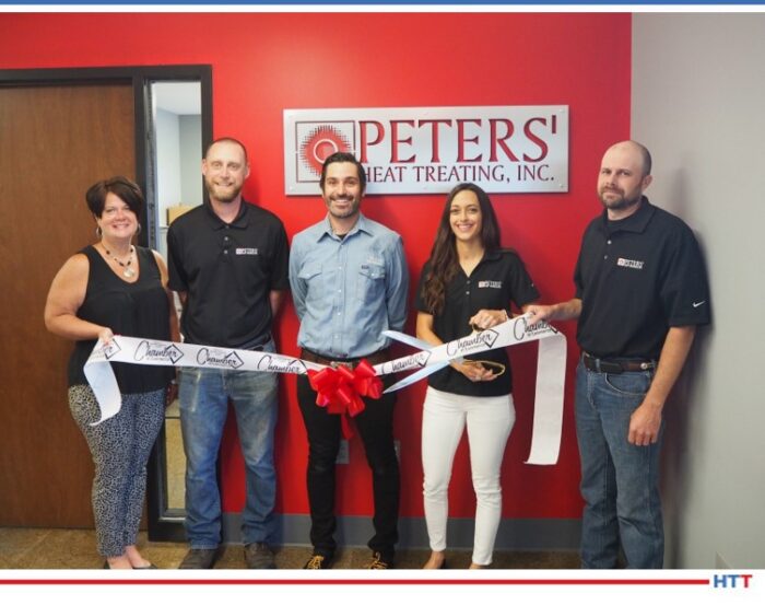
Ribbon Cutting with the Owners: Doug and Jackie Peters (founders), Diana Wilkosz (VP), and Andy Wilkosz (President) (photo source: Peters' Heat Treating, Inc.)
Additionally, Peters' Heat Treating also announced two new lines of business: aluminum alloy processing and stainless steel black oxide.Vice President Diana Wilkosz shared in a recent interview, "We added these two new lines because of the growing demands from the automotive, aerospace, energy, and defense industries. We are also working on Nadcap certifications."
The company specializes in vacuum processing, atmosphere heat treating/integral batch quench processing, laser heat treating, aluminum alloy processing, carburizing, scale free aging/stress relieving, cryogenics, black oxide coating, induction processing, nitriding/FNC and the proprietary Nitreg nitriding processes.
After being in their original facility for 40 years, this expansion, that covers 32,000 square foot of manufacturing space, has provided them the opportunity to expand and update their vacuum line, provide room to add new vacuum furnaces, as well as increase their product offerings and continue to grow the now 60-employee business.
“We are excited to consolidate our services and knowledge in a way that maintains our history and dedication to the local community and industry while providing us the runway for a successful future,” said Andy Wilkosz, newly named president in 2019 and son-in-law of founders Doug and Jackie Peters. “These current times are challenging, but we know our business and the country will persevere.”
In addition to Peters' Heat Treating, the family also co-ownsLaser Hard, a robotic laser heat treating company.
“It’s been a pleasure to be a part of the local community and to help companies grow,” Doug Peters said. “Probably the thing I’m most proud of is the great people I’ve had the opportunity to work with. I’ve watched them buy houses and have children, and now their kids are having children.”
Induction hardening has played a critical role for decades in heat treating. In this Heat TreatToday Technical Tuesday feature, Kyle Hummel, Professional Engineer at Contour Hardening, shares his engineering insights on the necessity of induction-hardened components for automotive powertrains. As a manufacturer with in-house induction hardening or a commercial heat treater, learn about viable considerations in moving forward with your induction hardening process.
This article appeared in the edition June 2020 edition of Heat TreatToday'sAutomotive Heat Treating magazine.
Induction hardening has played a crucial role in the automotive industry for many decades and is poised to continue that role into the future as the industry prepares for the inevitable shift to electric vehicles. Over the past 15 years, the emphasis on fuel economy, increased quality standards, and the emergence of other heat treat methods have drastically altered the design and necessity of induction-hardened components for automotive powertrains.
Transformation of Component Design
Increased residual compressive stress, minimal distortion, and the ability to selectively harden portions of a component are some of the main characteristics that have made induction hardening a popular choice for gears and shafts in the automotive industry. From the early 1980s to the 2000s the number of gears being hardened via induction was tremendous. The strength requirements for gears in four- and six-speed transmissions demanded the added compressive stress coupled with low distortion for noise reduction that induction hardening provides. As transmissions have increased to eight, nine, and 10 speeds over the past 10 years, the peak loading conditions of the gears has decreased, opening up the availability of other heat treat options. Low distortion processes such as nitriding and ferritic nitrocarburizing have now been successfully utilized in these gear applications because the gears do not require the high amounts of residual compressive stress. As the volume of these gears has decreased, other highly complex and high-volume components still remain great candidates for induction hardening.
Constant velocity joints (CVJ) rely on induction hardening and should remain relatively unaffected by the transition to electric vehicles. CVJs are typically designed for individual vehicle platforms rather than transmission platforms which can encompass a number of different vehicles. This leads to a greater variety of different part numbers to be hardened, and most CVJs typically require hardening in more than one region. These aspects require the need for specialized equipment to harden the CVJs that are difficult to adapt to other types of components.
Automated Hardening of CVJs
In addition to CVJs, the advancements in powder metal (PM) capabilities in the past decade have also created a surge in the number of PM components that require induction. PM sprockets and other uniquely shaped components that require high wear resistance are paired with induction hardening to replace traditionally machined components.
As the technology in PM has improved, the ability to achieve full density at varying depths below the surface has recently led to the production of internal gears that can be induction hardened for added strength and wear properties. Other technically complex components such as sliding panels, stator shafts, and input shafts continue to utilize induction to increase strength and wear resistance in specific areas. As engineers continue to push the design limits of components, specialized induction hardening equipment with precision control, higher power, and shorter heat times is required to successfully develop a robust process.
Unique Technical Challenges
Induction Hardening Machine (both figures)
The technical challenges for induction heat treaters have increased with the added complexity of these components and the emphasis on several quality standards. It requires an entire team of engineers to provide input with coil design, process development, and adherence to quality standards. The days of having a print specification simply list a visual case depth and a surface hardness are a distant memory. Specifications now commonly require effective case depths at multiple locations, microstructure evaluations, and hardness and dimensional inspections. CVJs in particular can have over 35 metallurgical inspection points and over 25-dimensional inspection points. The component complexity has also led to the need for increased crack inspection. Sharp corners, thin walls, lubrication holes, and the use of higher carbon steels have led many parts to require nearly 100 percent inspection for cracks.
Along with the print specifications, heat treaters must also comply with the growing number of technical standards required to be an approved automotive supplier. IATF 16949 Quality Management System, AIAG’s Heat Treat Assessment (CQI-9), ASTM standards, and customer specific requirements can create a vast network of conditions that must be examined and constantly monitored to ensure compliance. Although these added requirements can be an inconvenience, the quality of parts being produced has significantly improved and that ultimately leads to safer and more reliable vehicles for the customer.
Adapting to the Future
Unfortunately, the technical challenges and increased quality requirements of automotive parts do not always come with higher margins. With the competition in Mexico and Asia, U.S. manufacturers with their own in-house heat treating and commercial heat treaters must continue to find ways to remain competitive. The volatility of OEM volume predictions and platform start and end dates requires manufacturers and heat treaters to be dynamic in capacity considerations. With induction hardening, having excess capacity at a variety of different frequencies and power capabilities can be crucial to landing the next job. Automotive work can frequently come in due to unplanned downtime at a competitor, or on a customer’s own heat treat line. If your organization does not have the ability to produce test samples almost immediately, that opportunity for valuable work will be missed. Having the knowledge and equipment to understand and provide testing for dimensions is another key to offering value to automotive customers. The ability to test parts green and immediately after hardening can drastically reduce scrap and rework and can be a crucial selling point to customers.
The piece by piece processing of induction hardening is suited well for automation and the benefits reach beyond simply reducing labor costs. The reduction in tooling changeovers not only reduces wasted time, it also improves the quality and consistency of the product. With tight dimensional tolerances on final parts, slight variations in heat treat patterns can be eliminated by dedicating and automating a heat treat line. The ROI for automating a cell, including temper and rust preventative application can be as little as six months with the added bonus of supplying a more consistent part to the customer.
High-volume, complex components provide special challenges for induction heating.
The modern induction hardening facility should be moving to automate not only the production itself, but also the inspections, factory information systems, and ERP systems. Inspections such as eddy current can be automated to reliably inspect 100 percent for proper hardening and even crack detection. Automated microhardness equipment can save lab technicians hours of valuable time they would have spent waiting at the tester. These technologies, when used appropriately, can result in more efficient processes that produce higher quality parts at competitive prices.
Although the landscape of the automotive industry in the next 15 years is as exciting as it is uncertain, induction hardening will continue to be a vital process that is utilized into the future. The changes over the past 15 years have produced more complex components with stricter requirements that must be processed with greater efficiency. Induction hardening suppliers must remain focused on keeping pace with the developments in technology that continue to improve the heat treat industry as a whole in order to remain relevant and be a value-added process for automotive customers.
About the author: Kyle Hummel is a licensed Professional Engineer who has worked for Contour Hardening for 14 years as a metallurgical engineer focusing on process development and quality improvement.
For more information, contact Kyle at khummel@contourhardening.com or (317) 876-1530 ext. 333.
Dr. Steve Offley, Product Market Manager, PhoenixTM
Knowing the precise temperature from within your continuous heat treat process is now possible. In this Heat Treat Today Technical Tuesday article, Steve Offley, “Dr. O,” Product Marketing Manager at PhoenixTM identifies how this innovative temperature profiling system can help you with your continuous aluminum brazing or other processes.
This article appeared in the edition June 2020 edition of Heat Treat Today’sAutomotive Heat Treating magazine.
In the automotive industry, aluminium brazing is key to many of the manufacturing processes used to produce radiators, condensers, evaporators, etc. The quality of the brazing process is important to the performance and product life for its intended function. A critical requirement of the brazing process is the optimization and control of the product temperatures during the complete brazing process. A valuable tool to achieve such requirements is the use of ‘Thru-process’ temperature profiling as a direct alternative to the traditional trailing thermocouples as discussed in the following article. Obtaining the product temperature profile through the brazing furnace gives you a picture of the product/process DNA.
The Basic Brazing Principle and its Temperature Dependence
Aluminium brazing employs the principle of joining aluminium metal parts by means of a thinly clad soldering ‘filler’ alloy, whose melting point is lower than the base/parent metal.
As part of the brazing process, control of the product temperature is critical to achieve selective melting of the filler alloy 1076°F-1148°F (580°C -620°C) to allow it to flow and fill the joints between the parent metal substrate without risk of melting the substrate itself. Often the difference between the melting points of the two materials is small, so accurate temperature monitoring through the entire furnace is critical to the success of the brazing process.
[spacer color="3366ff" icon="fa-lightbulb-o"]
PhoenixTM works with major automotive radiator manufacturer customizing a brazing barrier solution to meet their specific application needs.
PhoenixTM was approached by a major automotive radiator manufacturer in the USA. The manufacturer had a specific need for a reliable CAB brazing monitoring system that would withstand heavy use, approximately 45 runs per week. The two companies collaborated to design a unique barrier solution which was adopted for standard profiling use.
“The new barrier is great; the operators love them. All those design iterations paid off.”
It is estimated that barriers supplied back in 2014, which have seen routine use over five years and are still operational, have accumulated in excess of 2,500 successful profile runs without damage or any wear problems. Over the same period, many conventionally designed barriers have been scrapped due to HF acid damage of cloth and microporous insulation. The customer for this reason has now standardized the TS08 design for all their CAB profiling activity.
[spacer color="3366FF" icon="Select a Icon"]
Critical Challenges of the Brazing Process
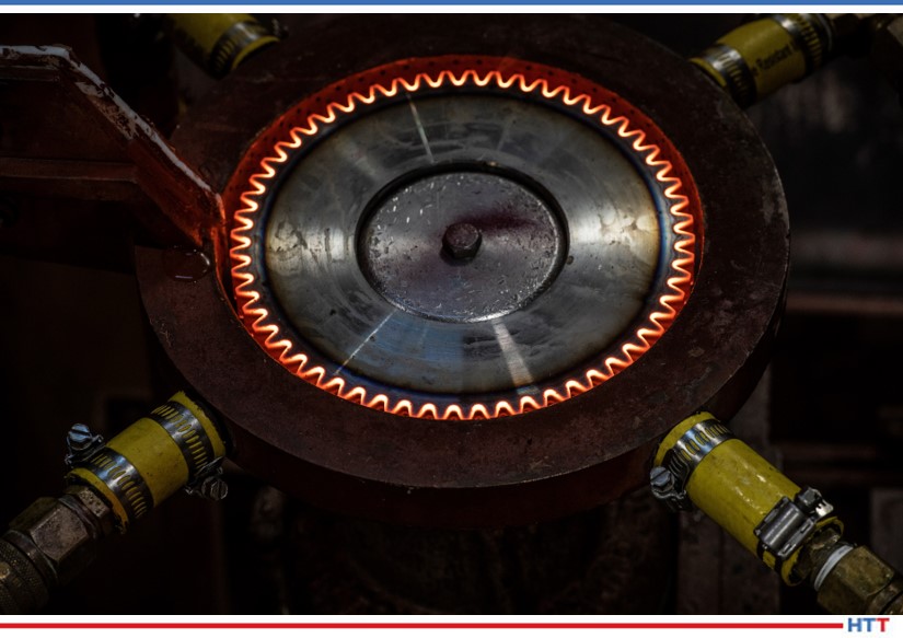
The system enters the continuous aluminum brazing furnace with product being monitored.
Prior to any brazing process, it is important that the substrate surface is prepared correctly to allow the brazing process to work correctly. Surface preparation before brazing may involve thermal degreasing where the substrate temperature is elevated to drive off lubricants. A second more important procedure is the removal of any surface oxide layer to allow wetting, and therefore flow of the brazing filler alloy over the parent substrate. Unfortunately, aluminium is easily oxidized and the resulting aluminium oxide (Al2O3) prevents such wetting processes. Therefore, prior to brazing, the oxide layer needs to be eliminated. In most cases, cleaning of the substrate layer is achieved by the application of a corrosive flux, which in a molten state, dissolves the oxide layer.
A data logger with 10 thermocouple channels.
The type of flux used must be matched to the application substrate and filler alloy composition. A common brazing process used today is that of the Nocolok Process® in which the flux is potassium fluoroaluminate K 1-3 AlF4-6, a white powder deposit.
For the reasons discussed above, elimination of oxygen - and especially water - from the brazing process is a critical requirement, so the furnace is generally run under a nitrogen atmosphere (Controlled Atmosphere Brazing ‘CAB’ Oxygen < 100 ppm, Humidity < -40°F /-40°C). The design and construction of monitoring systems needs to be carefully considered, as discussed later, to ensure that the furnace atmosphere is not contaminated (by oxygen and water), in any way.
Design Principles and Challenges of a "thru-process" Brazing Furnace Monitoring System
The ‘thru-process’ profiling system concept is based on the principle of sending a data logger through the brazing furnace which is protected from the heat and harsh brazing environment by a thermal barrier. Multiple thermocouples connected to the product test piece (radiator), which are connected directly to the data logger, measure the product temperature (and furnace) as it travels through the furnace storing the information in the data logger memory. The resulting temperature profile can be reviewed, analyzed, and a validation report generated. As the system is compact and travels with the product, there is no need to use the cumbersome and potentially hazardous challenge of feeding (and retrieving) long thermocouples through the furnace, as required in the use of traditional trailing thermocouples.
Innovative Thermal Barrier Design
The thermal barrier has the job of providing thermal protection to the data logger. Although this is the case for aluminium brazing, the barrier also needs to be designed in such a way as to avoid damage to itself from potentially hostile corrosive chemicals generated in the furnace, and prevent contamination of the CAB atmosphere from barrier outgassing materials.
Traditionally, thermal barriers are manufactured employing micro-porous block insulation wrapped in high-temperature glass cloth. During use, moisture trapped in the insulation block is released within the barrier cavity where it can form hydrofluoric (HF) acid in combination with chemicals in the brazing flux. Over only a short period of time, the highly corrosive HF acid can cause significant damage to both the barrier cloth and insulation. This compromises the integrity of the barrier, reduces its thermal performance, and potentially creates a dust contamination risk to the process.
Air trapped in the micro-porous insulation block and within the barrier cavity during heating can expand and escape from the barrier into the furnace. Obviously, being made up of 21% Oxygen (O2 (g)), the air will contaminate the CAB environment, and potentially create a risk of aluminium oxide formation resulting in wetting/brazing problems.
To eliminate the damage to barriers, extend operational life expectancy, and minimize outgassing of air (O2(g)) or moisture, PhoenixTM developed a unique new TS08 specifically for the demands of CAB brazing.
As shown in figure 1, the logger draw loading mechanism significantly reduces the amount of insulation cloth that is exposed to the aggressive flux. Prior to supply, the insulation block is preheated in a high vacuum and back flushed with nitrogen (N2(g)) to drive out any air trapped in the porous insulation structure. For processes where any air outgassing is a significant contamination risk, it is possible, with specific barrier configurations, for customers to purge the small barrier cavity of any remaining air with a supply of low-pressure Nitrogen (N2(g)).
Figure 1: The brazing barrier is designed to give low height thermal protection to the data logger. Designed with front loading logger tray and metal construction to limit exposure of insulation and cloth materials to corrosive HF. Available with nitrogen purge facility option to remove any risk of O2 (g) outgassing into the furnace.
PhoenixTM Datalogger with 6, 10 or 20 Channels
Front loading logger tray with encapsulated thermal insulation protecting from HF
Thermal breaks reduce heat conduction to logger
Heat sinks provide additional thermal protection employing phase change technology
Mineral Insulated Thermocouple inserted into radiator fins
Rear barrier optional Nitrogen feed nozzle for pre-run purging of insulation and barrier cavity of air (02(g))
Unveiling the Mystery of your Brazing Furnace with a ‘thru-process’ Temperature Profile Trace
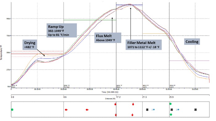
The key temperature transitions/phase of the brazing process are clearly shown on a typical temperature profile as in figure 2.
Figure 2. Thru-process temperature profile of a typical CAB brazing furnace showing critical temperature transitions.
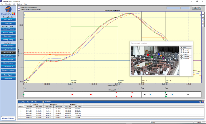
Thermal profile graph displayed in the Thermal View Plus software package.
The brazing system is supplied with Thermal View Plus software, which is designed to provide full analysis and reporting tools for monitoring the brazing process against the monitoring requirements detailed in Table 1.
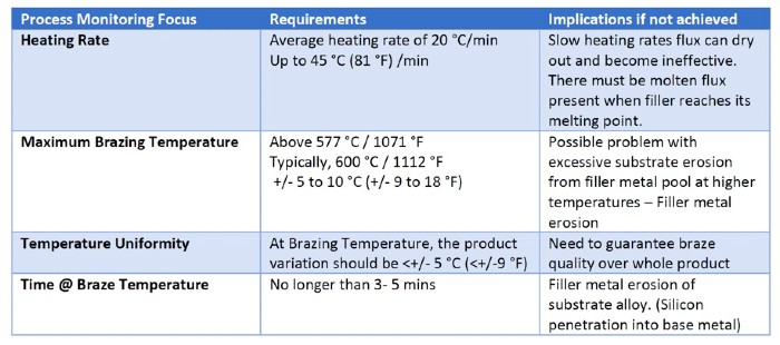
Below in Table 1 is a summary of the target temperature transitions in the CAB brazing process, the impact on process, and possibly, the quality of the brazed final product.
The PhoenixTM brazing system is supplied with Thermal View Plus software, which is designed to provide full analysis and reporting tools for monitoring the brazing process against the monitoring requirements detailed in Table 1.
Table 1. Critical monitoring requirements for the CAB brazing process.
Overview
The PhoenixTM ‘Thru-process’ brazing system provides a rugged, reliable, and clean solution for performing product temperature profiling of Automotive CAB brazing furnaces. Providing the means to Understand, Control, Optimize and Certify the brazing heat treat process.
About the author: Steve Offley, “Dr. O,” the product marketing manager at Phoenix TM, is an experienced global marketing manager with a demonstrated history of working in the industrial temperature monitoring industry over the last 25 years.
Piotr Skarbiński, Vice President of the aluminum and CAB Product Segment at SECO/WARWICK (photo source: secowarwick.com)
A global manufacturer of electric cars based in Asia has purchased Controlled Atmosphere Brazing (CAB) technology. The CAB technology will be designed for brazing large size car battery coolers.
The supplier, SECO/WARWICK, believes that green technology is increasingly in-demand. "The electric car industry," says Piotr Skarbiński, Vice President of the Aluminum and CAB Products Segment at SECO/WARWICK, "is constantly investing in technologies for the production of advanced vehicles and systems in which these vehicles are equipped.”
The current and forecast development of electric cars and the related rapid and long-term increase in demand for battery coolers is very positive for the segment of the company dealing in aluminum soldering and heat treatment.
A global automotive supplier has placed an order for an electrically heated continuous belt brazing furnace to be installed in Mexico in the 4th quarter of 2020.
Abbott Furnace Company will design and manufacture the industrial furnace for brazing of fuel delivery components and their Mexico location will install and provide after sale support of the four (4) zone line that is rated for 2,150° F and includes a 24” wide belt and silicon carbide domed muffle.
Evolution of ideas and transitions to more innovative and efficient methods of heat treating are common themes in this ever-changing world. In this article, Dennis Beauchesne, GeneralManager atECM USA, Inc., explores the integration of heat treatment for in-line machining cells and the benefits and efficiencies experienced.
This articlearticle first appeared in the latest edition (June 2020) of Heat TreatToday’sAutomotive Heat Treat magazine.
Introduction
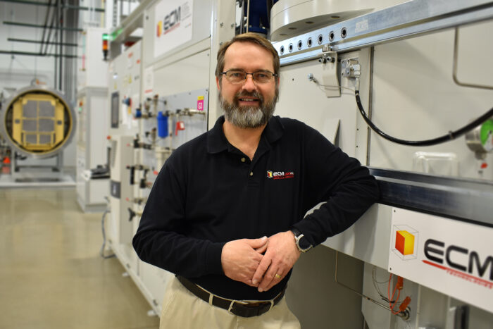
Dennis Beauchesne, General Manager, ECM-USA, Inc.
Heat treating in the automotive industry has evolved tremendously over the last 20 years. From the dinosaur pusher furnaces of yesterday to the low-pressure carburizing and high-pressure gas quenching of today, we are now embarking on new concepts with not only in-line processing, but also automated single piece and bulk loading in small batches. Modern heat-treating equipment is now being sized to fit into single-piece flow lines with small batches and in-line with pre- and post-machining centers. This article will examine the integration of heat treatment for in-line machining cells, and the influences for the customer to provide an overall quality system. These details will be compared to batch or continuous batch heat treatment as commonly known in the automotive industry.
Over the last 20 years, low pressure vacuum carburizing (LPC) has been proven as the choice for carburizing high production parts in a variety of markets all over the world. It is the process of choice for many high-fatigue and low-distortion parts; thus, it can be used in conjunction with vacuum oil quenching (VOQ) and, in most cases, high pressure gas quenching (HPGQ). Advantages of this process include the fact that equipment is more easily maintainable, flexible, and independent from operators’ intervention than traditional atmosphere carburizing. In addition, reduction of effluents from the process are significantly decreased. A benefit of this process is that the furnace equipment is used more along the lines of a machining cell, which has most commonly been reserved for induction heat treating in the past. With the added benefits of LPC, the importance of strength and fatigue life have increased beyond previous process capabilities; in turn, LPC in-line processing has been considered more frequently.
The rapid shut-down/cool-down (5-6 hours) of a vacuum system is a significant advantage compared to the convoluted days of cooling an atmosphere system. Simply shutting down one day per week due to scheduled maintenance, without the need for supervision, or use of additional utilities required for idling during downtime, is also highly desirable. Other facets of the equipment and process have allowed vacuum furnace equipment to be more conducive to high production manufacturing. This includes recipe ease, process repeatability, and load-to-load processing flexibility in a continuous flow environment. These additional benefits allow the use of part-specific “recipes” while allowing for high production through the system and insuring individual metallurgical requirements.
High pressure gas quenching (HPGQ), using a dedicated quenching cell, is often linked with LPC for several reasons. Some of the most important reasons are:
to provide a cleaner environment in the plant
to remove oil-quenching tanks and the need for oil on a production floor
to eliminate the need for pits in the floor or managing oil containment
to obtain a safer, more ergonomic environment via the elimination of open flame and hot surfaces
to achieve more precise distortion control of dimensionally critical parts
to reduce or eliminate post-heat treat machining needs
to eliminate post-heat treat blasting (for cleanup)
to eliminate post-heat treat washing (for quench oil removal)
to eliminate post-heat treat washer effluent (sludge) removal
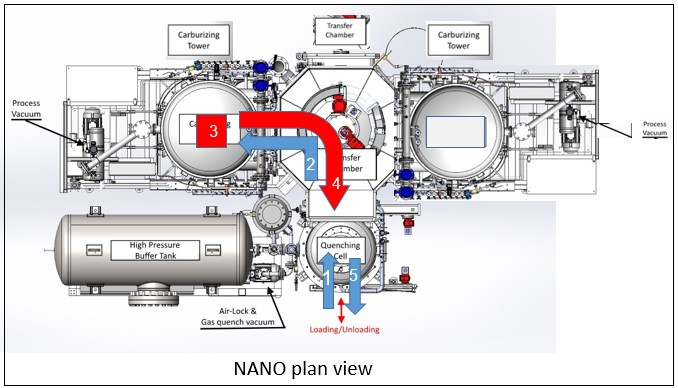
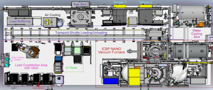
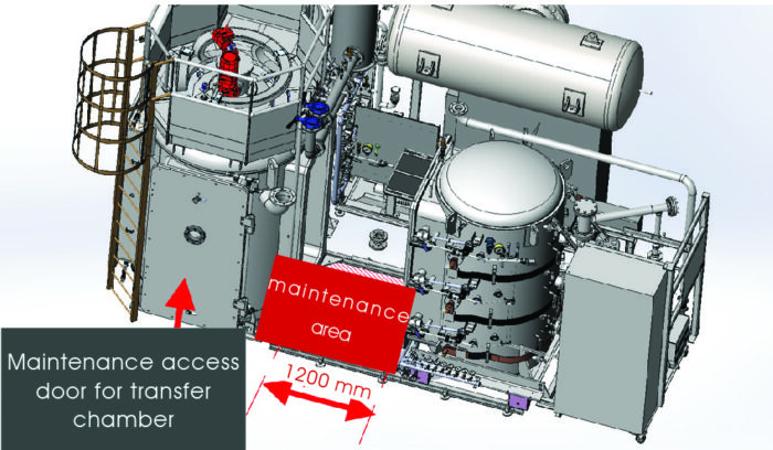
Plan view of in-line heat treatment system
ECM Technologies has been manufacturing LPC and HPGQ systems for over 25 years and designed an innovative in-line system, called NANO. The name NANO is appropriate in terms of the equipment design as the load size is smaller than traditional loads and the physical equipment is more compact than furnaces more commonly used today. The system has also been designed with maintenance and expandability in mind. The premise of the design is to be able to process loads as quickly as
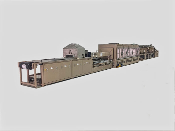
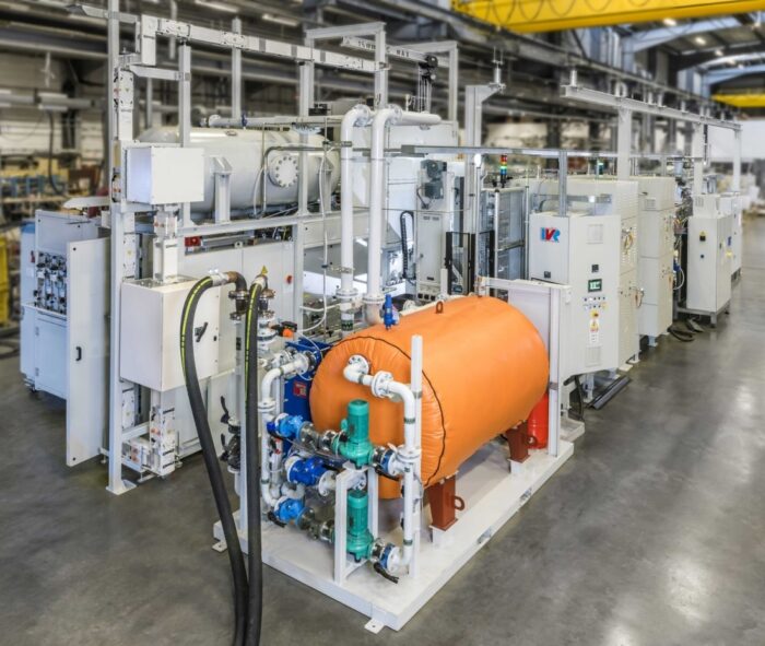
In-line heat treatment system being fully-tested prior to shipment to customer
every 7.5 minutes per load. The system is modular in production capacity with growth from three to six heating cells, which can be supplied. The system is ready for a low number of loads, with flexible needs for varying part requirements, or can be maximized to provide throughput for modern high-demand production needs. The NANO consists of four basic modules, the heating module (typically two), the transfer module, and the high-pressure gas quench module. The gas quench module uses a 20 bar gas quench system. With a smaller chamber size and the ability to quench at 20 bar, materials that were not able to be quenched in gas are now applicable for gas quenching. This gas-quenching method will open up this technology to more applications that were limited by core and surface hardness requirements in the past.
Using the NANO as the heat treat equipment base, automation completes the overall single- piece flow system to provide true in-line heat treating. The parts can be presented to the system in bulk or in single-piece trays. These parts can then be loaded and virtually tracked through the system using vison systems.
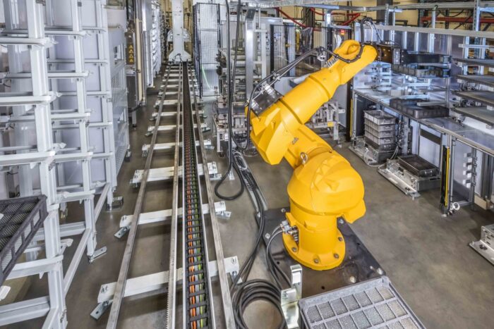
In-line heat treat installation showing robotic arm facilitating automated loading/unloading
The NANO accommodates a workload size of 24” wide x 20” deep x 10” high (600mm wide x 500mm deep x 250mm high); see Figure 1. Workload parts can be processed on industry-typical alloy fixturing or more preferably on CFC fixtures. The goal of designing the system, beyond better maintenance accessibility and gradual production increase, is low distortion and in-line production flow.
By processing loads with less work pieces, part uniformity and distortion are identical from part to part as the “3D” or 3-sided heating elements heat the parts uniformly and homogenously. These elements are designed not to sag onto the parts and provide adequate clearance for the automated loader to perform accurate transfers within the system.
Automation and Integration
The system has been designed for manual or automated loading. Manual loading can be as simple as manually loading basic fixtures or baskets, and manually loading through the system and subsequent processes. Automated loading can be from a simple robot platform that loads parts onto a small fixture from a single part flow to the handling of many pieces in a bulk load. The robot can handle all functions of the installation from loading single parts on to the fixture to placing the loads in the furnace, and then, cryogenic treatment, tempering and eventually back to a single-piece flow. The system is also capable of checking surface hardness and registering the data to be kept with the load report. This total integration can allow for a smaller footprint and less manpower in the heat treat area.
In addition, automation can handle typical small bulk-loaded parts. Some of these parts are traditionally processed using mesh belt furnaces but can now be processed by this vacuum furnace in-line system. Bulk loads are loaded into basket-like CFC trays and can be weighed and processed as needed to ensure the quality of each load.
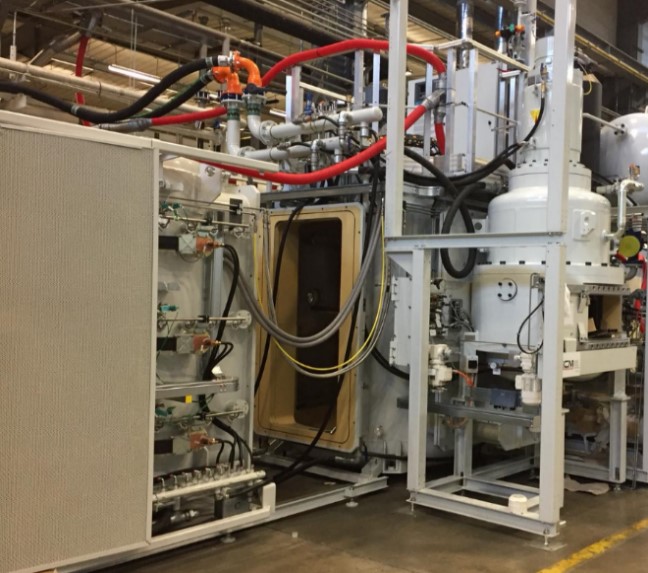
Low pressure carburizing installation showing easy access for maintenance
In-line heat treating is not just for carburized products, it can be for hardening, brazing, annealing, and integrated with post treatments—such as cryogenic and complex tempering operations. This allows the NANO to fit into various markets for many different types of heat treatments, not only steel parts, but for special heat-treating processes as well.
Equipment layouts are typically developed to accommodate specific applications. They can be as simple as a manual load station to a robot loading single-piece flow parts onto smaller fixtures or loading bulk parts into baskets for processing.
Maintenance Features
In-line processing, as well as bulk processing, together with automation to load and unload single-piece production are not the only key items in this design. Maintenance and operation were high on the list of criteria as well. Maintenance features such as ease of access are important on production equipment, but especially within heat treating. With the smaller load sizes and equipment, cool-down is significantly faster resulting from the smaller, water-cooled heating zones. Once cooled and released to atmospheric pressure, the system can then be opened via the full opening maintenance access door for easy, internal service effort. However, this is rare because all mechanisms that require control and quick review are located on the exterior of the system and outside the vacuum chamber. This allows for ease of access to all major components and reduces the need to stop or interrupt production. Additionally, for hot zone service, each heating module can be rolled away from the central transfer module to allow easy access to all hot zones in that module. This allows for easy-open access without the hindrance of confined spaces.
Distortion Evaluation
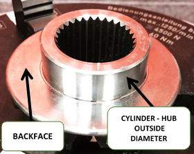
Figure 2. Differential gear used for distortion evaluation
Using a differential gear (Figure 2), we monitored two characteristics, which are usually requested for this type of gear, and tabulated the results. This evaluation was done using a current day load that will be illustrated as a large batch (FLEX) and those processed in the NANO will be a small batch (NANO). The two characteristics that have the most influence: (1) Cylindricity (circularity) of the outside diameter and the runout between the same diameter and (2) “Backface” flatness of the gear teeth.
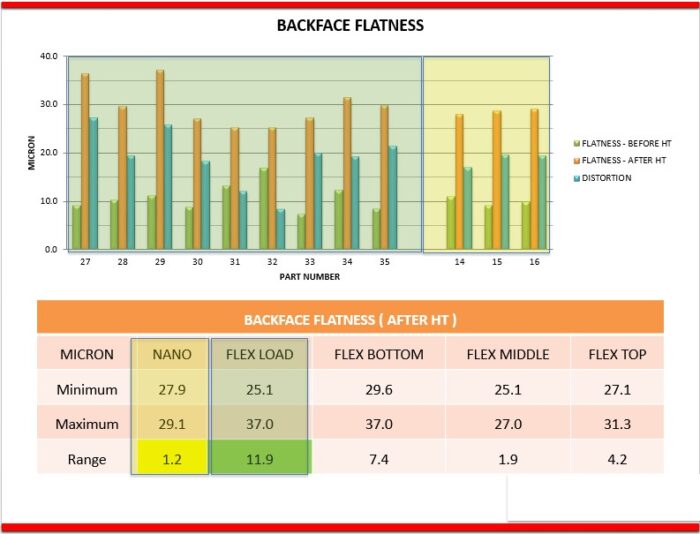
Backface flatness (Figure 3) shows greater variance through the large batch with further distance from the nitrogen used in quenching in the range of 11.9 µm. For the small batch results, the backface flatness distortion range was limited to only 1.2 µm. This uniform result is directly connected to the uniform quenching in the smaller load. This allows for parts to be processed closer to actual machined dimensions (near net shape), as well as being handled on an in-line production basis.
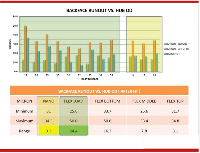
The runout analysis (Figure 4) shows a uniformity for the small batch with a spread of only 3.2 µm across the load. In the large batch, you will see a wider range of distortion uniformity using 10 bar nitrogen quenching with a spread of 24 µm. This is most likely due to the lower layers being further from the vertical down flow of gas through the load. These results are quite extraordinary for a full-size load.
Figure 4. Backface flatness comparing large batch processing (FLEX LOAD) and one-piece processing (NANO)
Conclusion
In-line processing can now be a common thought in the layout of future facilities. In practice, it is a growing aspect of the heat-treating world. With the new NANO vacuum furnace system and automation options, better part-to-part quality can be achieved along with better control of metallurgical parameters and results. Overall, streamlining heat treating into production cells throughout the facility allows for better part flow, and optimally sizing products for the production of particular throughput requirements.
References
[1] Beauchesne, D., “FNA2016 - LPC with OIL & GAS Quenching” (2016)
[2] Esteve, V. & Lelong, V., “LPC - What Does it Mean to Metallurgy” (ASM-Mexico 2016)
[3] Welch, A. & Lelong, V., “How it’s done and Why: Transitioning Parts from Atmosphere Carburizing to Low Pressure Vacuum Carburizing” (HT 2015)
About the author: Dennis Beauchesne is the general manager of ECM USA and brings experience of over 200 vacuum carburizing cells installed on high pressure gas quenching and oil quenching installations. He has worked in the thermal transfer equipment supply industry for almost 30 years, 18 of which have been with ECM USA.
In this article by Lee Gearhart, Principal Engineer, Materials and Processes, Moog, Inc., and Chair, Aerospace Metals Engineering Committee, read about a “real time” heat treat inquiry regarding the interpretation of changed oil quenching effectiveness testing in AMS 2759, and Lee’s desire to ensure that the heat treater’s system maintains its effectiveness.
This articlearticle first appeared in the latest edition (June 2020) of Heat Treat Today’s Automotive Heat Treatmagazine.
* Please see the bottom of the article to view the AMS2759 sections to which Lee refers.
The Query:
Lee Gearhart, Principal Engineer, Materials and Processes, Moog, Inc., Chair, Aerospace Metals Engineering Committee
A gentleman, to whom I’ll refer as Mr. XXXX, sent the following query to SAE, the publisher of Aerospace Materials Specifications. The subject line was as follows: “Clarification of AMS 2759G for Committee ‘E’.”
The letter read:
I would like to get some clarification about AMS 2759, Revision G, paragraphs 3.10.3 through 3.10.3.1.5.5. My issue, as an independent testing lab, is the terminology used in 3.10.3.1.5.1 and 3.10.3.1.5.3., and how
I am to determine the acceptance criteria for the hardness in the center diameter of the quench effectiveness samples supplied to us by heat treating companies. Let me walk through the steps that lead up to the determination of minimum hardness at the center of the diameter of the coupon prepared.
Paragraph 3.10.3.1.2 states specific size test bars to use for the quench effectiveness testing, based on the alloy, in sub-paragraphs a., b., c., and d. For 4130 (a.), use 1.5” long, 0.50” diameter bar and for 4330V (c.), use 7.5” long, 2.5” diameter bar. Then, we cut the test coupon from this specimen todetermine hardness at the center diameter, per 10.3.1.4.
Next, we have to determine whether this hardness result, taken at the center diameter, conforms to the spec, and here is where my issue is. Paragraphs 10.3.1.5.1 and 10.3.1.5.3 both state, “…shall not be less than the hardness on the end-quench hardenability curve corresponding to the diameter of the specimen…” So, if I am to use the diameter of the specimen as my guide from paragraph 3.10.3.1.2, a.and c., then the end-quench result on the mill cert corresponding to 8/16 would represent the 0.50”diameter, and 40/16 would represent the 2.5” diameter. ASTM A255 has you stop taking readings on the Jominy bar at 32/16 (2.0”), so there would not be a result on the Mill Cert for the 40/16 requirement.
I don’t believe this is the correct depth. I believe the end-quench result corresponding to one-half the diameter would be the appropriate depth to use as a minimum requirement, since we are taking the hardness reading at one-half the diameter; in the center of the diameter. So, the end-quench result on the mill cert corresponding to 4/16 would represent the 0.50” diameter and 20/16 would represent the 2.5” diameter bar. These requirements are more stringent and would better represent the effectiveness of the quench media to properly quench the specimens and correlate this back to the certified values of the material based on the mill cert reading for the corresponding J values.
Please review this and consult with the Committee to see if this would better represent the intent of these paragraphs for acceptance of quench effectiveness.
The Response:
Because of my position as chairperson of the Aerospace Metals Engineering Committee, the question eventually made its way to my desk. Here is my response:
When reading your question, it suddenly struck me – you’re missing the secret decoder ring! In other words, you cannot directly compare an oil quenched sample to a water quenched (Jominy) test coupon.
Allow me to give you a long-winded explanation that I wrote for Committee E on Steel for the Aerospace Materials Division, the committee that has jurisdiction of AMS2759 on Heat Treating of Steel. The committee had been asked for an explanation of what the 3.10.3 Quench System Monitoring is supposed to do; after the text in italics, I’ll directly answer you.
Let me start by noting the whole purpose of 3.10.3.1, which was to provide a means for a heat treater to demonstrate that their oil quenching system continues to work well. If they do the steps outlined in 3.10.3.1, they do not need to seek approval from their customers for this method. If they choose a different method for monitoring the quench system, they need approval by the cognizant engineering organization (CEO). Since a heat treat firm will probably have many customers with different CEO’s, it makes sense to have one test procedure on which all can agree.
The method starts with the heat treat quality function choosing one of the suggested alloys and bar size configurations noted in 3.10.3.1.2. The constraints of the choice are that the hardenability of the sample has to be enough that they will get full hardening in the center, but not so much that a bar 1.25 times the diameter chosen would get full hardening. (That prevents me from using an air hardening steel, which will not show any difference when my quench system degrades.) If the three choices in 3.10.3.1.2 (a-c) will not work, then (d) offers an out, using other materials and dimensions, established in pre-production testing.
Prior to initial production, and quarterly afterward, the heat treater runs one of the test bars in a typical or simulated production load. They then section out a half-inch slice from the middle of the length of the bar and test the hardness. If in the quarterly testing it remains above the acceptance criterion established by the pre-production testing, their quench system passes.
Figure 1. Cert 4130
Accept/reject criteria is that the hardness in the center meets the hardness of the end-quench hardenability curve done by the original mill, or someone else, per ASTM A255, on the material used for the test. AMEC wanted this because using the generic curves in ASTM A304 is too general, and the curves are routinely done by the steel mills. I’ve attached an example cert (Figure 1) for some 4130 we bought not long ago, and at the bottom of the page are the Jominy numbers! They range from 51 to 24; so, which should I use?
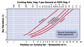
To find the correct accept/reject hardness, I go to a curve that shows what Jominy distance in sixteenthsof an inch reflects the cooling at the center of the size of test bar I use. If I’m using 4130 steel from my certified lot of material, the specimen is half inch in diameter, and the attached Timken curves say that the center of a half inch bar cooled with an H of 5 (good agitation) corresponds to a Jominy distance of 3/16, so the hardness required is 49 HRC. If I use a different curve, like the other one attached from an old Copperweld brochure (Figure 2), I get a Jominy distance of 31⁄2, so my acceptance number is somewhere between 49 and 46, so I’ll use 48 HRC. This difference is small, and unimportant, since I’m only using it to show if there is degradation in the oil quench performance.
This “compare it with the Jominy curve done by the mill” is only for the 4130 and 4330V specimens noted in 3.10.3.1.5.1 and 3.10.3.1.5.3. For specimens made of 4140, we call out HRC 44 in the center and HRC 50 in the 3⁄4 radius position of the 11⁄2 inch diameter specimen.
So, the 8/16 position on the Jominy curve doesn’t mean it’s appropriate for a half inch diameter specimen – it’s just pointing to the spot on the Jominy bar that’s 8/16 inch from the end that gets sprayed with water. The “secret decoder ring” I mentioned are the “Jominy cooling rates” or the “Pages from Timkin” attachment (Figures 3). These translate the speed of quenching at any sixteenth- inch position of a Jominy bar to the equivalent rate of quenching of surface, mid-radius, and center of bars of different size quenched in various coolants. I tend to use the “Jominy cooling rates” attachment, which I got from an old Copperweld Steel brochure, but since the Timkin Practical Data Handbook for Metallurgists is on the web for free, it’s probably a more universal reference.
Hence for 0.50” diameter 4130 bar, the center hardness should be that corresponding to between 3 and 4 sixteenths of an inch. For the 2.5” diameter bar, quenched in mildly agitated oil, the cooling rate at the center would be represented by the 14/16” position on the Jominy bar. Maybe 15/16” – it’s kind of hard to read. Hence you read the data from the mill cert FOR THE STEEL FROM WHICH THE PIECES WERE MADE and use those numbers as accept/reject. HTT
About the author: Lee Gearhart, P.E., has worked for Moog, Inc. since 1982 and is currently Principal Engineer, Materials and Process Engineering. In addition to being a worldwide resource for the company, Lee is the current chair of the Aerospace Metals Engineering Committee, where much of the discussion on heat treating specifications occurs.
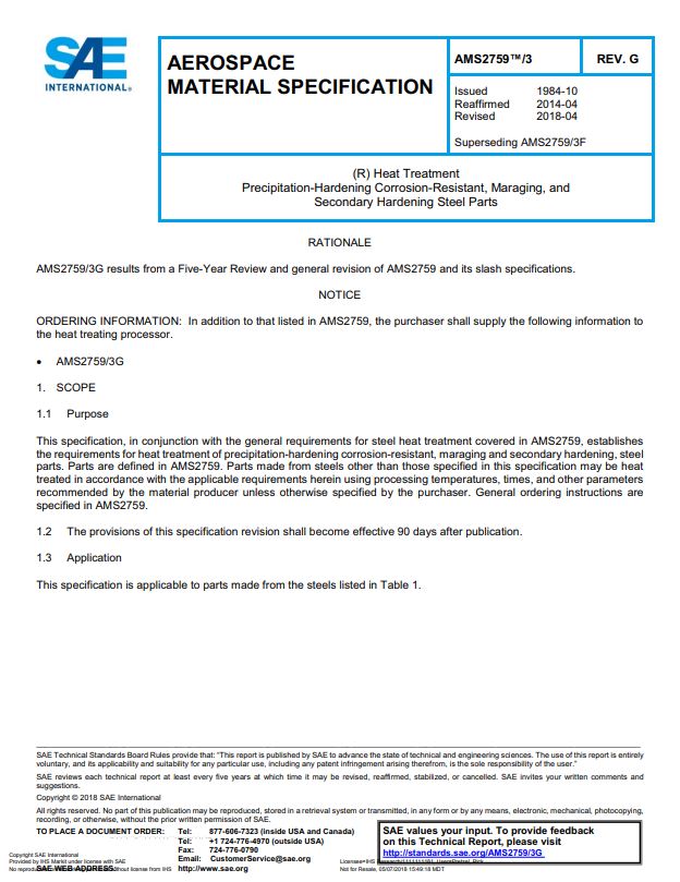
*Section 3.10.3 from AMS2759 Heat Treatment of Steel Parts(This section is one of the big changes to AMS2759 revision F, April 2018, which was then tweaked to revision G in August 2019)
The sections to which the article discusses is 3.10.3.1, 3.10.3.1.2 (a-d), 3.10.3.1.5.1 and 3.10.3.1.5.3
3.10.3 Quench System Monitoring
The quench system includes the quench volume, type of fluid, recirculation velocity and uniformity, and heat exchange capacity. The consistency of the quench system shall be monitored quarterly, by processing test parts, as outlined below, which are capable of detecting changes in the cooling characteristics of the system. Testing of water quench systems is not required. Quench system monitoring test procedures other than those described in 3.10.3.1 shall be approved by the cognizant engineering authority. When destructive mechanical property testing is required for part acceptance, quench system monitoring is not required.
3.10.3.1 Test Specimen Requirements
3.10.3.1.1 Test Specimen Alloy/Configuration
3.10.3.1.1.1Round specimens of carbon or low alloy steel, of appropriate hardenability and dimensions shall be used. Selection of the specimen dimensions/hardenability combination shall be aimed at achieving full hardening (e.g., 95% martensite) at the center of the specimen. The specific combination of alloy/dimensions chosen shall be such that the specimen would not be capable of achieving full hardening at 1.25 times the diameter chosen for the test specimen. The length of the test specimen shall be at least three times the diameter.
3.10.3.1.1.2The test specimens used for the initial and subsequent evaluation of a particular quenchant shall be from the same alloy and preferably the same chemistry heat of material to eliminate material chemistry and hardenability differences from the alloy selection. Hardenability results shall not be lower than that represented by requirements in 3.10.3.1.5.
3.10.3.1.2Test specimen alloy/dimensions shall be one of the following:
4130 round bar, minimum 1.50 inches (3.81 cm) long, 0.50 inch (1.27 cm) nominal diameter.
Other material and dimensional requirements established in pre-production testing or as specified by the cognizant engineering organization. See 8.5 for shape equivalent guidelines.
3.10.3.1.3Test Specimen Processing
Quarterly quench system monitoring tests shall be run with a typical or simulated production load. Heat treat loads shall be processed in accordance with the appropriate AMS2759 slash specification requirements.
3.10.3.1.4Specimen Testing Requirements
After quenching the test specimen, a 0.5-inch-thick specimen shall be cut from the center of the test specimen length and prepared for hardness testing in the untempered condition. Specimen shall be prepared to ensure it is free from overheating. The minimum hardness at the center of the diameter shall meet the hardness requirements of the approved procedure in 3.10.3.
3.10.3.1.5Test Specimen Hardenability
3.10.3.1.5.1Round Bar Specimen 4130
After quenching, the center of the diameter shall not be less than the hardness on the end-quench hardenability curve corresponding to the diameter of the specimen when tested in accordance with ASTM E18. The end-quench hardenability curve shall be the actual hardenability curve determined in accordance with ASTM A255 on the material used for the test specimen.
3.10.3.1.5.2Round Bar Specimen 4140
The hardness in the center of the diameter shall not be less than HRC 44 and the 3/4 radius shall not be less than HRC 50 when tested in accordance with ASTM E18.
3.10.3.1.5.3Round Bar Specimen 4330V
The hardness in the center of the diameter shall not be less than the hardness on the end-quench hardenability curve corresponding to the diameter of the specimen when tested in accordance with ASTM E18. The end-quench hardenability curve shall be the actual hardenability curve determined in accordance with ASTM A255 on the material used for the test specimen.
3.10.3.1.5.4If other combinations are established, the accept/reject criteria shall be as specified in the ordering information.
3.10.3.1.5.5It is the responsibility of the heat treater to provide the material and hardenability data specified above.
3.10.3.2 Any failures shall be documented by the heat treater’s corrective action system.
3.10.3.2.1As a minimum, if the test specified in 3.10.3 fails, the quench medium shall be analyzed as specified in 3.10.3.3.
3.10.3.3 Quench Media Control
3.10.3.3.1Each new shipment of quenchant from a vendor shall meet the requirements for the particular quenchant listed in 3.10.3.3.1.1 through 3.10.3.3.1.3 as applicable. The vendor shall furnish a certificate of conformance stating that the quenchant meets the requirements including, in addition to the vendor designation, the cooling curve, the cooling rate curve, the maximum cooling rate, and:
3.10.3.3.1.1For mineral oil based quenchants, the certificate shall also include the viscosity, flash point, temperature at the maximum cooling rate.
3.10.3.3.1.2For vegetable or ester-based oil quenchants, the certificate shall also include the viscosity, flash point, temperature at the maximum cooling rate.
3.10.3.3.1.3For polymer quenchants, the certificate shall also include the undiluted pH and viscosity. The pH, viscosity, maximum cooling rate and the temperature at the maximum cooling rate shall be provided at 20% concentration by weight.
3.10.3.3.2Cooling curve tests shall be performed semi-annually, or when required by corrective action (3.10.3.2), in accordance with ASTM D6200, ISO 9950 or JIS K 2242, ASTM D6482, or ASTM D6549, as applicable to the specific quench medium. If no alternative limits have been established by pre-production tests or specified by the cognizant engineering authority, exceeding the following limits compared to the initial shipment of quenchant shall be cause for corrective action:
For mineral oils: Temperature of the Maximum Cooling Rate: (±68 °F) (37.8 °C) Maximum Cooling Rate: (±25 °F/s) (13.9 °C/s)
For vegetable or ester-based oils: Maximum Cooling Rate: (±25 °F/s) (13.9 °C/s) Temperature of the Maximum Cooling Rate: (±68 °F) (37.8 °C)
For polymer quenchants: Maximum Cooling Rate: ±15% Temperature of the Maximum Cooling Rate: ±15%
The rebuild included a new 330 stainless steel muffle, new silicon carbide heating elements, new cooling sections, and new furnace controls to meet CQI-9 requirements. The CQI-9 controls package includes data acquisition, preventative maintenance alerts, remote connectivity, furnace parameter trending, and temperature deviation alarms.
The partner chosen for this rebuild, Gasbarre Thermal Processing Systems, designs, manufactures, and services a full line of industrial thermal processing equipment, offering batch and continuous thermal processing equipment for both atmosphere and vacuum applications as well as a full line of alloy fabrications, replacement parts and auxiliary equipment.
Eric Ford, Vice President of Sales and Marketing, Graphite Metallizing Corp.
In this Technical Tuesday original article, read how an automotive manufacturing plant is able to solve high-temperature bearing failures by upgrading to bearings that use a self-lubricating material that can operate in extreme temperatures. Author, Eric Ford, Vice President of Sales and Marketing at Graphite Metallizing Corp., shares how these bearings decreased the need for unplanned and costly maintenance of parts in the case study that follows.
An automotive engine manufacturing plant in the Midwest upgraded the bearings in their gas nitriding ovens after encountering numerous failures with rolling element bearings.
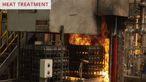
An example of a flame curtain in an industrial setting (Photo source: Graphite Metallizing Corp)
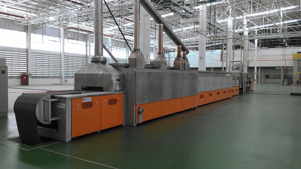
This large manufacturing plant runs automated gas nitriding furnaces for treating their various engine components. A flame curtain, at the entrance to the furnace, produces a vertical stream of combustion products to minimize both the infiltration of room air into the furnace chamber and the disruption of the furnace atmosphere inside. The bearings for the conveyor rollers, closest to the flame curtain, are subjected to intense heat for a short period of time, about 30 seconds, which is enough to cook the grease in the bearings and degrade their performance.
In many automotive plants, these machines are running 24/7 for up to six months at a time. Any breakdown of this equipment has serious consequences in terms of profitability and delivery schedules.
Excessive Downtime
The plant was having trouble with the repeated failure of the rolling element bearings, located just prior to the furnace’s flame curtain. These bearings were failing within six months, causing unscheduled maintenance and downtime. Though there was an automatic grease system, temperatures of approximately 300°F resulted in the grease being cooked away rapidly, resulting in conveyor roller seizure.
When the bearings seized, production on the line stopped. The furnaces then needed time to cool sufficiently for maintenance personnel to be able to access and replace the bearings. Starting the system up again wasted yet more production time.
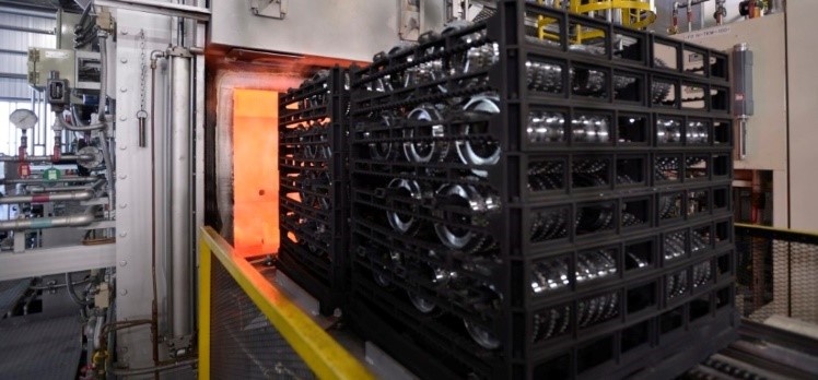
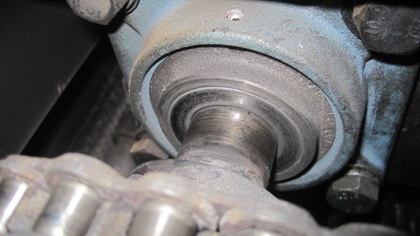
The conveyor transporting the parts has bearings to support the load and convey the product through the furnace. (photo source: Graphite Metallizing Corp)
It was taking three people about four to six hours to replace the bearings and start the furnace again each time the bearings failed. These unscheduled shutdowns cost tens of thousands of dollars in production loss, labor, and materials. In addition to the expense of the downtime, there was also the added safety risk of handling parts when unloading the furnace and performing maintenance on the equipment, which was still hot.
Successful Trials
At a heat trade show during this time, the production manager of the plant learned about Graphalloy bushing materials; Graphalloy is the name for a specific family of proprietary graphite/metal alloys developed by Graphite Metallizing Corp of Yonkers, NY. Its featured qualities include non-galling, corrosion resistant, dimensionally stable, and can operate at temperatures from cryogenic to higher than 1000°F (538°C). These materials work very well in severe environments and services due to their self-lubricating properties – no grease or oil is required. There are more than 100 grades of these high-temperature bushings which are designed for specific conditions.
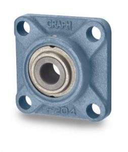
Flange Bush 845 (photo source: Graphite Metallizing Corp)
Soon after the show, company representatives went to the plant and proposed a simple drop-in replacement for the current greased bearing flange block assemblies. The production manager agreed to test a few of the company's 4-bolt flange blocks with copper bushings, and they were installed a few weeks later.
The target was a difficult one: The production supervisor said that a doubling of the lifespan of the roller element bearings would enable the plant to stick to its twice-annual scheduled maintenance intervals. By achieving this goal, unscheduled maintenance shutdowns would be avoided.
During the one-year trial period, the high-temperature bushings were a success. Based on the positive result, the production manager installed additional bushing assemblies of this brand type during subsequent scheduled maintenance dates, until all furnaces had been converted to new self-lubricating bushings.
The original bearing assemblies, installed over six years ago, have been operating without a single failure or showing any appreciable wear.
By replacing the metal bearings with newer graphite bushings, the automotive company eliminated at least two unscheduled shutdowns and dozens of hours of maintenance work per year. According to the production manager, using this has saved this automotive giant hundreds of thousands of dollars to date.
This is one of the best thermocouple basics articles you’ll read this year. It covers the different types of thermocouple, questions to consider when deciding which type of thermocouple to use, as well as a fascinating discussion on thermocouple wire and wire insulations.
Ed Valykeo, Thermocouple Specialist, Pelican Wire
John Niggle, Business Development Manager, Pelican Wire
Learn about thermocouples and their place in your heat treat department in this Technical Tuesday original Heat TreatToday article by John Niggle, Business Development Manager, and Ed Valykeo, Thermocouple Specialist, at Pelican Wire, Naples, FL.
This article appears in the upcoming edition (June 2020) of Heat Treat Today’sAutomotive Heat Treating magazine.
The six common types of temperature measurement sensors used in industry are thermocouples, RTD’s, infrared, bimetallic, liquid expansion and change of state devices. Thermocouples are by far the most used of all these sensors. Their popularity is due to their simplicity and ease of use, as well as their size and speed of response. For these reasons, thermocouples are commonly used in the automotive industry for purposes such as component testing, for example brakes, exhaust gas temperature measurement, and in oven temperature profiling in paint systems. Most importantly for readers of this article, thermocouples are widely used in heat treat applications as well.
A thermocouple is a simple, robust, and cost-effective temperature sensor used in a wide range of temperature measurement processes. It consists of two dissimilar metal wires that produce a voltage proportional to a temperature difference between either ends of the pair of conductors. Thermocouples are self-powered and require no external form of excitation.
Thermocouple materials can be divided into two groups based on their compositions. The two types are base metal and noble metal thermocouples. Base metal thermocouples are made of inexpensive and readily available metals such as nickel, iron, copper and chromium. Noble metal thermocouples are made of costly elements such as platinum, rhodium, gold, tungsten, and rhenium. This article will focus on base metal thermocouples.
For convenience, base metal thermocouples are identified by letter, K, J, T, E, and N. Type K and J are the most widely used in industry. Base metal thermocouples are chosen for use based on emf output, temperature range, and the most often overlooked, environment. Base metal thermocouples are used in a wide range of industries including medical, diagnostics testing, vehicle engines, gas appliances such as boilers, water heaters, and ovens. They are widely used in the heat treat industry. Thermocouples are invaluable in monitoring and validating critical processes.
Type K Thermocouple
Type K thermocouples are nickel based so they work well in most applications. Type K thermocouples have good corrosion resistance. They’re inexpensive, accurate, reliable, and have wide temperature ranges. Maximum continuous temperature is 2012°F (1,100°C).
Advantages:
Good for high temperature applications
Appropriate for use in oxidizing or inert atmospheres at temperatures up to 2300°F (1260°C)
Best in clean oxidizing atmospheres
Disadvantages:
Not recommended for use under vacuum or partially oxidizing atmospheres
Not for use in sulfurous atmospheres unless protected
Not recommended in a vacuum at high temperatures
Type J Thermocouple
Type J thermocouples consist of a positive leg of iron and a negative leg of copper nickel alloy. They have smaller temperature ranges and shorter lifespans at higher temperatures than the Type K. They are equivalent to the Type K in terms of expense and reliability. It is a good choice for general purpose applications.
Advantages:
Relatively high thermoelectric power
Appropriate for use in vacuum, air, reducing, or oxidizing atmospheres
Disadvantages:
The Iron leg is susceptible to oxidation
Should not be used in sulfurous atmospheres
Iron leg limited at subzero use due to rusting and embrittlement
Type T Thermocouple
Type T are very stable thermocouples and are often used in extremely low temperature applications such as cryogenics. They are found in other laboratory environments as well. The type T has excellent repeatability between –380°F to 392°F (–200°C to 200°C)
Advantages:
Very stable
Moisture resistant
Useful to 700°F (370°C)
Can be used in vacuum, reducing, or inert atmospheres
Disadvantages:
Lower temperature range
Type E Thermocouple
Type E are nickel-chromium versus copper-nickel thermocouple alloy combinations that produce the highest emf per degree of any of the base metal thermocouple alloy combinations. Type E can be used in temperatures from 300°F to 1600°F (149°C to 871°C).
Advantages:
Good in oxidizing atmospheres
Higher temperature range than type J
More stable than type K
Has the highest output EMF of any standard type
Disadvantages:
Vulnerable to sulfur attack
Only short-term use in a vacuum
Only short-term use under partially oxidizing conditions.
Only short-term use in alternating cycles of oxidation and reducing atmospheres
Type N Thermocouple
Type N thermocouple alloys are nickel based. Type N shares the same accuracy and temperature limits as the Type K. Type N has better repeatability between 572°F to 932°F (300°C to 500°C) compared to the type K.
Advantages:
Good in oxidizing or inert atmospheres
Less aging as compared to Type K
Better suited for nuclear environment
Disadvantages:
Do not use in sulfurous atmospheres
Slightly more costly than Type K
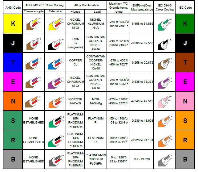
Thermocouple Color Code Chart
Questions to Ask When Choosing Thermocouples
Besides the metallurgy of the thermocouple, consideration needs to be given to the style of sensor, probe or wire, and construction of the wire that carries the signal from the sensor to the instrument reading the signal. The purpose of the sensor is to achieve the same temperature as the process it is measuring and relay that temperature to the process instrumentation. The process being measured should dictate the type of sensor. If the process would in some way damage the sensor or invalidate its accuracy through corrosion, flow, pressure, or another condition, then a probe style sensor would be best. If the temperature being measured is in a static environment like a paint booth in an automotive assembly plant, an engine and exhaust system on a test stand, heat treating oven, or even a fluid that is not flowing, then a wire style sensor should work. The wires can even be tack welded in smelting or forging operations in one-time use applications.
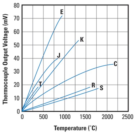
Thermocouple Output Voltage for Types E, J, T, K, C, R, S
Thermocouple Wire
Thermocouple wire construction or design has many factors to consider. These factors include accuracy, resistance to heat, abrasion, moisture and chemicals, flexibility, and durability as well as size constraints Accuracy falls into two classifications, Standard Limits of Error and Special Limits of Error. Special Limits of Error wire or conductor shares the same metallurgy with Standard Limits of Error but has better accuracy as the name implies. Standard Limits of Error wire or conductor would have a wider understood range of inaccuracy. A quick rule of thumb for understanding the accuracy divergence between special and standard limits of error; special limits of error tolerance ±2.0°F (±1.1°C) up to 500°F (260°C) and then 0.4% beyond 500°F (260°C). As an example, the tolerance for a special limit thermocouple at 1000°F would be ±4.0°F (±2.2°C) (1000 X .004). For a standard limit thermocouple, the quick rule of thumb is ±4.0°F (±2.2°C) up to 500°F (260°C) and then 0.8% beyond 500°F (260°C). Using the same example, the tolerance at 1000°F (538°C) for a standard limit thermocouple would be ±8.0°F (±4.4°C) (1000 X .008).
Extension grade is a third class or grade of wire that should also be mentioned. Extension grade wire should not be confused with either of the thermocouple grade wires mentioned previously. Extension Grade wire in fact should not really be considered a thermocouple grade wire, but rather a signal wire that carries the signal of the temperature being measured by the sensor to the process instrumentation. Typically, extension grade wire is not exposed to the same conditions that the probe and thermocouple wire would be. It is usually removed at a distance from the process being monitored, and as such, the requirements for the construction of the extension grade wire are not as stringent. For instance, the heat resistance requirement for the insulation would not be as high or critical. The maximum temperature extension grade wire is certified to is 392°F (200°C).
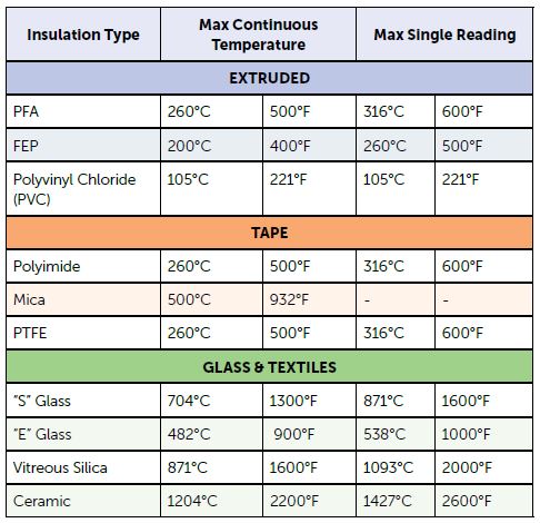
The choice of insulation is a critical factor in thermocouple wire design. Selection of insulation is influenced greatly by the atmosphere in which the wire will be operating. In the case of extension grade wires, the conditions will not be very demanding, for the most part, so PVC is a commonly used insulation. It has sufficient heat resistance for most environments, although not to the maximum certification temperature extension grade wire of 392°F (200°C), and has adequate moisture, chemical and abrasion resistance as well as flexibility. PVC is also an economical choice for insulation.
However, in many instances especially as the distance to the sensor and process temperature being monitored decreases, PVC does not have the properties necessary to withstand the conditions of those environments. This is particularly true of heat resistance with PVC being rated to 221°F (105°C ) only. Other insulations offer much higher heat resistance with the additional benefits of abrasion, moisture and chemical resistance if required. These other insulations can be broken down into 4 categories. Those categories are: extruded insulating compound, tapes, fiberglass, and high temperature textiles. Common extruded higher heat resistant extruded insulations would be fluoropolymer compounds like FEP and PFA. Heat resistance of these compounds range from 392°F to 500°F (200°C to 260°C). They exhibit excellent abrasion, moisture, and chemical resistance as well. They are also cost-effective solutions within their functional temperature ranges. Wires using fluoropolymer compounds for insulation are many times chosen for their smaller overall size.
Tapes most often used for insulating thermocouple wires are polyimide, PTFE, and Mica. They are normally chosen for higher heat resistance requirements. In the case of polyimide tape, it would be chosen when a lighter weight wire is desired. A desirable feature of PTFE tape is that it is a thermoset. Depending upon the tape, heat resistance is rated at 500°F (260°C) for polyimide and PTFE to 932°F (500°C) for the mica insulation. The polyimide tape has good abrasion, moisture and chemical resistance as does the PTFE. Mica is usually used to supplement PTFE and fiberglass insulations in dual insulation wire constructions. Flexibility of the wire is reduced with the use of mica tape. The overall dimensions of tape insulated wires are like wires with extruded insulation, except for mica taped wires as the mica tape increases the wall thickness of the wire.
Wire insulation types and temperature rating
If higher heat resistance is required, then the next logical insulation is fiberglass. Fiberglass insulation can be braided on the individual conductors, then braided again over both conductors to form the overall jacket; or the individual conductors can have fiberglass spiral wound, or ‘served’, around them with a braided overall jacket over both. This determination in construction is usually dependent on the gauge of the wire and the limitations of the braiding equipment.
The two types of glass encountered are E glass and S glass. E glass is rated for 900°F (482°C) and S glass for 1300°F (704°C). Glass insulated wires will have slightly larger walls than extruded, and tape insulated wires yield slightly larger overall diameters. While giving the user higher heat resistance than extruded or taped insulations, glass sacrifices some abrasion, moisture, chemical resistance and possibly some flexibility depending upon the wire gauge. Glass is seen in the automotive world because of the higher temperature requirements for component testing.
For more demanding heat resistance applications, there are the high temperature resistant textile insulations. These would be vitreous silica and ceramic fibers. Ratings for these insulations are 1600°F (871°C) for vitreous silica and 2200°F (1204°C) for ceramic. These insulations are also applied to wires on braiding equipment. These textiles produce a heavier wall than any of the other insulations previously mentioned so wires constructed with materials will have larger overall dimensions as well. Additionally, the insulations would be considered somewhat fragile and would lack abrasion resistance so they would best be used in a static environment. Applications requiring moisture or chemical resistance would not be recommended for these.
There are other options for thermocouple wire construction available including the gauge of the conductors, whether solid or stranded, shielding, drain wires, twisting, cabling, custom color coding or even applying a metal overbraid such as stainless steel or Inconel. While there are many constructions that are considered standard, not all applications are the same and there may be multiple processes with a facility requiring different types of sensors and wires. Given the critical nature of temperature in many manufacturing processes and testing scenarios, it is important that the data is gathered accurately, reliably and consistently to be relayed to the process instrumentation where the validity of the results can be trusted. It is best to consider as many factors and requirements as are known then consult with a manufacturer for the sensor and wires that would be best for the different processes being monitored.
About the Authors: John Niggle has been the business development manager at Pelican Wire since 2013 and has prior sales experience in process instrumentation. Ed Valykeo, a 40-year veteran in the wire industry, many with Hoskins, is a thermocouple specialist who has worked with Pelican for 10 years.


 To learn more about Laser Hard, listen to the Heat Treat Radio episode in which they are featured.