Let’s discover new tricks and old tips on how to best serve air and atmosphere furnace systems. In this series, Heat Treat Today compiles top tips from experts around the industry for optimal furnace maintenance, inspection, combustion, data recording, testing, and more. Part 3, today's tips, examines AI and record keeping. Look back to Part 1 here for tips on seals and leaks and Part 2 here for burners and combustion tips.
This Technical Tuesday article is compiled from tips in Heat Treat Today's February Air & Atmosphere Furnace Systems print edition. If you have any tips of your own about air and atmosphere furnaces, our editors would be interested in sharing them online at www.heattreattoday.com. Email Bethany Leone at bethany@heattreattoday.com with your own ideas!
1. Use AI To Simplify Your Maintenance
Contact us with your Reader Feedback!
"cloud view of heat treating operation" Source: NITREX
Simplify your maintenance! Today, using artificial intelligence (AI) software allows the “Cloud” to do the hard work. NITREX has introduced QMULUS, a web-based software solution, with each of its nitriding systems, which examines key parameters to determine if your furnace is having any issues. Gas flows, amperage, motors, and cycles are all monitored for health factors. But QMULUS is so much more than that. It also analyzes input usages and calculates the cost of each run; logs all data relevant to running processes more efficiently; and provides an easy and seamless cloud view of heat treating operations.
This is a very simple tip that is often overlooked when customers are focused on meeting production goals instead of the maintenance of their equipment. It is critical to record the operating settings of their furnace systems when parts are coming out at their best, or simply before issues arise. When something goes awry in the process and troubleshooting is required, service technicians hear all too often that there is no record of what the ideal or correct setpoints are for various systems. Nearly every item on a modern heat treating furnace (or in its control panel) has a setpoint or position that can be recorded or physically marked. Now, clearly some items are more critical than others when it comes to air and atmosphere settings. Below are a few items you’ll want to have setpoint/positioning records of before they require troubleshooting:
Flowmeter setpoints (at the furnace and generator)
Blower/pump/motor VFD setpoints (primarily frequency setpoints and ramp rates)
Manual or actuated damper positions on flues
Regulator setpoint (from pressure gauge or in-line test port)
High/low pressure switch setpoints
Any air/gas/atmosphere ratios for various recipe steps
Burnout frequency and duration (if applicable)
An added incentive to record these settings is the preventative maintenance benefit. The best way to avoid supply chain issues and delivery delays is to fix a problem before it grows into a bigger issue. When a setpoint/setting is correct but product quality begins changing, it is a warning sign that consumables may be approaching end of life (such as nickel catalyst in endothermic gas generators) or components require maintenance (such as air inlet filter replacements).
Let’s discover new tricks and old tips on how to best serve air and atmosphere furnace systems. In this series, Heat Treat Today compiles top tips from experts around the industry for optimal furnace maintenance, inspection, combustion, data recording, testing, and more. Part 2, today's tips, examines burner and flame safety. Look back to Part 1 here for tips on seals and leaks.
This Technical Tuesday article is compiled from tips in Heat Treat Today's February Air & Atmosphere Furnace Systems print edition. If you have any tips of your own about air and atmosphere furnaces, our editors would be interested in sharing them online at www.heattreattoday.com. Email Bethany Leone at bethany@heattreattoday.com with your own ideas!
1. Operating with a Multiple Burner System
Contact us with your Reader Feedback!
If a furnace or oven has a multiple burner combustion system with only one valve train, a multi-burner combustion safeguard should be used. This ensures that if one burner fails, they all go out.
Source: Bruce Yates, "Ten Tips for Safeguarding Combustion Processes"
#multiburner #combustion #safety
2. Regularly Inspect Retort Alloys
Source: Nitrex
Retort alloys must be inspected on a regular basis. Hot spots can be identified by bulges. Plastic deformation occurs due to overheating, causing the hotter section to bulge because it is surrounded by stronger metal. Inspect your retorts or radiant tubes for deformations. In addition, constant thermal cycling can cause problems with some alloys. Look for cracks in welds or near welds. Some leak detection methods can also detect alloy issues or overheating.
Localized overheating could indicate a problem with the burner or the heating element. Early detection and correction can save you a lot of money on expensive alloys.
Flame supervision may be defined as the detection of the presence or absence of flame. If a flame is present during the intended combustion period, the supervisory system will allow a fuel flow to feed combustion. If the absence of flame is detected, the fuel valves are de-energized.
This basic definition does not consider the hazard potential during startup or ignition, however. A dangerous combustible mixture within a furnace or oven consists of the accumulation of combustibles (gas) mixed with air, in proportions that will result in rapid or uncontrolled combustion (an explosion). It depends on the quantity of gas and the air-to-fuel ratio at the moment of ignition.
Source: Bruce Yates, "Ten Tips for Safeguarding Combustion Processes"
#flamedetection #combustion #valves
4. Remember that Flame Safety Starts with Purging
The sequence for flame safety starts with purging the furnace or oven. Purge time should allow for four air changes.
Fuel valves can — and do — leak gas. The purpose of purging is to remove combustible gases from the combustion chamber before introducing an ignition source. The four air changes in the combustion chamber are based on a worst-case scenario that includes having a burner chamber that is completely filled with gas.
Once airflow for purge is verified, the proof-of-valve closure is confined and safety limits are proven. Then the purge timer — which may or may not be integral to the combustion safeguard — determines the period of time required to evacuate the combustion chamber.
Source: Bruce Yates, "Ten Tips for Safeguarding Combustion Processes"
Let’s discover new tricks and old tips on how to best serve air and atmosphere furnace systems. In this series, Heat Treat Today compiles top tips from experts around the industry for optimal furnace maintenance, inspection, combustion, data recording, testing, and more. Part 1, today's tips, examines seals and leak points.
This Technical Tuesday article is compiled from tips in Heat Treat Today's February Air & Atmosphere Furnace Systems print edition. If you have any tips of your own about air and atmosphere furnaces, our editors would be interested in sharing them online at www.heattreattoday.com. Email Bethany Leone at bethany@heattreattoday.com with your own ideas!
1. Tip-Up Furnace Perimeter Insulation Maintenance Is Key to Efficiency & Quality
Contact us with your Reader Feedback!
Due to their construction, the insulation at the perimeter of a tip-up furnace is subject to more abuse than typical furnace insulation. Whether from the repeated stress of cycling the case open and closed — or from high temperature operation — fiber modules will eventually begin to shrink/compact. Be watchful for high case temperatures (or worse: case discoloration and paint damage) as a signal that insulation issues are present in that area.
Heat-damaged case wall Source: Premier Furnace Specialists
An air/atmosphere tight seal is critical for maintaining heating efficiency and process quality. Inspect the seal material around the furnace perimeter often and replace sections that are worn. Common perimeter seals are sand seals, fiberglass tadpole tapes, and insulating fiber blankets. These sealing materials are easy to keep on hand to ensure a quality seal is never delayed by lengthy lead times or supply chain issues.
Seals are everywhere on any furnace. Do you know where all the seals and leak points are? Rope gaskets is an obvious example; high temperature gaskets need to be flat, smooth, and unbroken. Another clear example is in the world of vacuum furnaces: O-rings need to be clean and protected from abrasion. Almost every item of your furnace is sealed in some manner. It is best to replace seals as part of a preventative maintenance program. While your nose can detect ammonia, vacuum leaks require special helium leak detectors and a lot of training. Your furnace manufacturer’s service technician can assist in identifying problem areas and developing a maintenance routine to keep your furnace running. And a simple electronic manometer is great to have handy for running leak-down tests using positive pressures. Auto supply stores sell inexpensive halogen detectors, and some people use smoke bombs to detect leaks.
According to "Dr. O" – Dr. Steve Offley, product marketing manager at PhoenixTM – temperature control of the heat treatment application is critical to the metallurgical and physical characteristics of the final product, and hence its ability to perform its intended function. Explore today's Technical Tuesday article to find the light at the end of your mesh belt furnace tunnel.
This article first appeared in Heat TreatToday’sFebruary 2022 Air & Atmosphere Furnace Systems print edition.
Dr. Steve Offley, “Dr. O" Product Marketing Manager PhoenixTM
Introduction – The Need for Accurate Product Temperature Measurement
Even though modern furnaces are supplied with sophisticated control systems, they are still not always capable of truly giving an accurate picture of the actual product temperature as it passes through the process. Temperature sensors positioned along the furnace give a snapshot of what the environmental temperature is possibly zone by zone. Furnace controllers, as the name suggests, can give confidence that the process heating is performed in a controlled manner but will never give an accurate view of what the actual product temperature is. When monitoring, it is important to be able to distinguish between process and product.
The challenge to any process engineer is understanding how the product heating cycle relates to the operation of the furnace. A furnace environment may be well controlled, but very different product temperatures can be experienced with variation in key properties such as product material, size, shape, thermal mass, and position/orientation in the furnace. Infrared (IR) pyrometers and thermal imagers can provide surface temperature measurements only and require line of sight, so they limit the areas of the product that can be measured. Setup can sometimes be complex considering surface characteristics (emissivity) and process background/atmosphere compensation. As with air sensors, being fixed, typically IR sensors only give information at that specific furnace location which prevents accurate calculation of soak times at critical temperatures. Without additional information, soak times and temperatures may need to be extended well beyond the target to guarantee the heat treat process is completed with confidence with an obvious compromise to throughput and energy conservation.
Product Temperature Profiling
To fully understand the operational characteristics of the heat treat process it is necessary to measure both the environment and product temperature continuously as it travels through the process. Such technique provides what is referred to as a “temperature profile” which is basically a thermal fingerprint for that product in that furnace process. This thermal fingerprint will be unique but will allow understanding, control, optimization, and validation of the heat treat process.
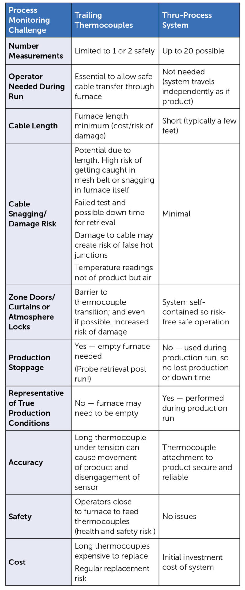
Table 1. Table showing the numerous benefits of thru-process temperature monitoring over traditional trailing thermocouples methodology for a mesh belt furnace
Historically, trailing thermocouples have been the go-to technique for product temperature monitoring. A very long thermocouple is attached to the product in the furnace. The data logger measuring the live temperature reading is kept external to the furnace. Although possible for static batch processes, the technique has significant limitations in a continuous/semicontinuous process, especially mesh belt furnaces (See Table 1).
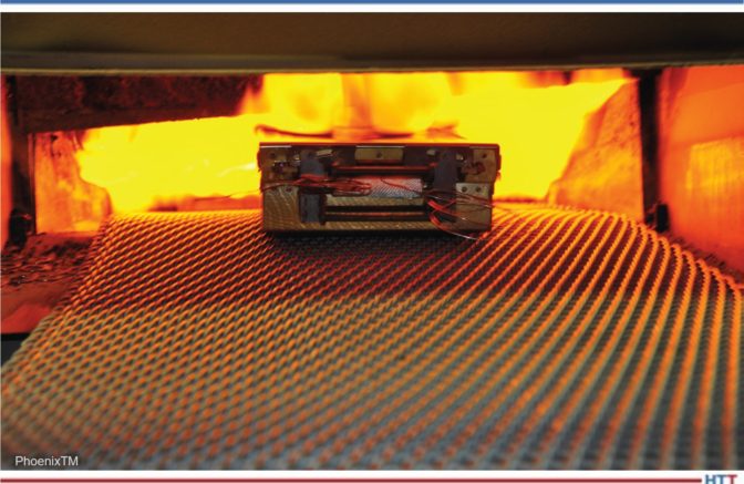
Fig 1. Robust multichannel data logger designed specifically for thru-process temperature profiling
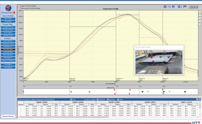
In thru-process temperature profiling the data logger travels with the product through the furnace. The data logger (Figure 1) is protected by an enclosure, referred to as a thermal barrier, which keeps the logger at a safe operating temperature (Figure 2). Temperature readings recorded by the data logger from multiple short length thermocouples can be retrieved post run. Alternatively, if feasible, the data can be read in real time as the system passes through the furnace using a two-way radio frequency (RF) telemetry communication option. The resulting temperature profile graph (Figure 3) provides a comprehensive picture — product thermal fingerprint — of the thermal process.
Fig 2. Thermal barrier protecting the data logger safely entering the conveyor furnace during the temperature profile run. Barrier size is customized to suit process credentials.
Fig 3. Typical temperature profile recorded for an aluminum CAB brazing line giving a complete temperature history for a brazed radiator at different product locations.(1)
Monitoring Your Heat Treat Process Temperature at the Product Level
Applying thru-process temperature monitoring product temperature measurement can focus on the micro product level which at the end of the day is most important. Static control thermocouples give an environmental temperature of the furnace in a zone, but this only reflects the true temperature wherever the thermocouple is located. This may be some distance from the product and may give some bias to its position if located on one side of the furnace. The thru-process monitoring system allows simultaneous product and/or air temperature measurement directly at the mesh belt. Monitoring can be performed across the belt with thermocouple placement on and in the core of the product and can be made to identify areas of different thermal mass resulting in differing heating characteristics.
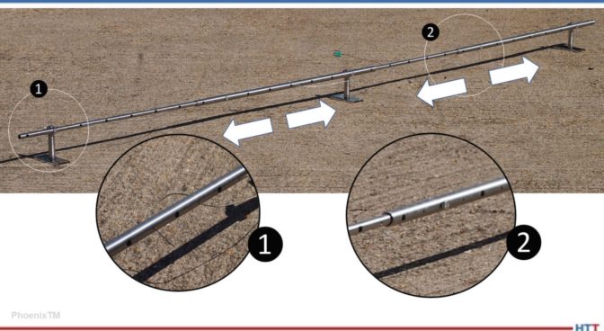
A useful strategy to use before looking at the product temperature is to thermally map the furnace. Thermocouples, connected to the data logger protected within the thermal barrier, are positioned across the mesh belt using a mount jig such as that shown in Figure 4. The jig guarantees reliable location of the measurement sensor run to run and adjustment means it can be adapted to different belt widths. Applying this principle, the thermal uniformity of air across the belt width through the entire furnace can be measured.
Fig 4. Thermocouple mount jig allowing accurate positioning of thermocouples (1) across the mesh belt width with adjustment to suit different belt dimensions (2).
Such data can be compared with zone control thermocouples to see what temperature differential the product may be experiencing at the belt level. Temperature imbalances across the belt and hot or cold spots along the process journey can be identified.
Furnace mapping can be further developed to satisfy either CQI-9/CQI-29 or AMS2750F pyrometry standards where a two-dimensional jig is constructed to perform the temperature uniformity survey (TUS).2 Employing the plane method, a frame jig is constructed to match the furnace work zone with the necessary number of thermocouples to satisfy the furnace cross section dimensions. Temperatures recorded over the working zone are compared to the desired TUS levels to ensure that they are within tolerance as defined in the standards.
Discover the True Root Cause of Your Furnace Problems
When it comes to product quality and process efficiency in any mesh belt furnace applications, temperature monitoring is only part of the story. Gaining an insight into what is physically happening in the product’s furnace journey can help you understand current issues or predict issues in the future, which can be corrected or prevented. To allow true root cause analysis of temperature related issues, it is sometimes necessary to “go to Gemba” and inspect what the product is experiencing, directly in the furnace. This is not always possible under true production conditions.
For a classic mesh belt furnace application such as controlled aluminum brazing (CAB), internal inspection of the furnace is not a quick and easy task. Operating at 1000°F, the cool down period is significant to allow engineers safe access for inspection and corrective action and then further delay to get the furnace back up to a stable operating temperature. Such maintenance action may mean one or two days lost production, from that line, which is obviously detrimental to productivity, meeting production schedules, satisfying key customers, and the bottom line.
In addition to process temperature problems there are many other production issues that can be faced relating to the furnace operation and safe reliable transfer of the product through the furnace. In the CAB process a day-to-day hazard is the build-up of flux debris. Flux materials used to remove oxides from the metal surface and allow successful brazing can accumulate within the internal void of the furnace. These materials are most problematic at the back end of the muffle section of the furnace where, due to the drop in temperature entering the cooling zone, materials condense out. Flux buildup can create many different process issues including:
Physical damage to the conveyor belt or support structure requiring expensive replacement
Reduction in belt lubricity creating jerky movement and causing unwanted product vibration
Lifting of the mesh belt creating an uneven transfer of products causing possible excessive product movement, clumping, or clashing
Reduction in inner furnace clearance creating possible product impingement issues and blockages
To prevent such problems, regular scheduled inspection and clean out of the furnace is necessary. This is not a pleasant, quick operation, and requires chipping away flux debris with pneumatic tools. Often requiring a furnace down time of 1 to 2 days, this task is only performed when essential. Leaving the clean-up operation too long can be catastrophic, causing dramatic deterioration in product quality or risk of mid-production run stoppages.
Figure 5. PhoenixTM Optical profiling ‘Optic’ System - Optical Profile View. System adaptable for both temperature and optical profiling.
Figure 5.1. High temperature thermal barrier for aluminum brazing system protecting camera and torches through CAB furnace
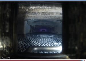
Figure 5.2 Video image in inner CAB furnace showing condition of inner furnace, mesh belt and product transfer
Figure 5.3. Identification of flux debris at back end of muffle furnace prompting scheduling of clean down operation
Optical Profiling – The Efficient Alternative
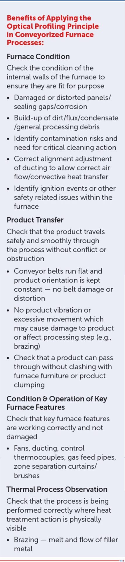
Optical profiling is a new complementary technique to that of thru-process temperature profiling. The innovative technology allows for the first-time process engineers to view the inner workings of the furnace under normal production conditions. Traveling through the furnace with the products being processed, the optic system gives a product’s eye view of the entire heat treatment journey. A thermal barrier, similar in design to that used in temperature profiling, protects a compact video camera and torch that are used to record a video of what a product would see traveling through the furnace (Figure 5). The principle is just like your car’s dash cam, the only difference being that your journey is being performed in a furnace at up to 1000°F. The resulting video, “Optical Furnace Profile,” shows process engineers so much about how their process is operating without any need to stop, cool, and dismantle the furnace. This allows safe routine furnace inspection without any of the problems of costly lost production and days of furnace down time.
Summary
Monitoring your mesh belt furnace from a temperature and optical perspective allows you to fully understand what truly happens in that black box. Understanding leads to better control, which helps you get the optimal performance out of your heat treat process from a quality, productivity, and energy efficiency perspective.
Don’t get left in the dark. Consider the power of temperature and optical profiling which will literally provide a light at the end of your furnace tunnel!
References:
[1] Steve Offley, “Unveiling the Mystery of Your Al Brazing Furnace with ‘Thru-Process’ Temperature Profiling," Heat Treat Today Magazine, June 2020, p40.
[2] Steve Offley, “Applying ‘Thru-process’ Temperature Surveying To Meet the TUS Challenge of CQI-9.” HeatTreatToday.com. June, 2019. https://www.heattreattoday.com/heat-treat-news/automotive-heattreat-news/applying-thru-processtemperature-surveying-to-meet-thetus-challenges-of-cqi-9/
About the Author:
Dr. Steve Offley, “Dr. O,” has been the product marketing manager at PhoenixTM for the last 4 years after a career of over 25 years in temperature monitoring focusing on the heat treatment, paint, and general manufacturing industries. A key aspect of his role is the product management of the innovative PhoenixTM range of ‘thruprocess’ temperature and optical profiling and TUS monitoring system solutions.
Heat Treat Todaysurveyed mesh belt industry manufacturers asking for feedback on information heat treaters should know. In this article, Abelard Escura, manager of Export at Codina, gives recommendations when to use specific belts, explains belt vocabulary, and shares trends they are excited about.
This article first appeared inHeat Treat Today’sFebruary 2022 Air & Atmosphere Furnace Systems print edition.
What mesh belt materials, belt weaves, and belt loading (lbs./linear foot or lbs./square foot) are recommended for various heat treatment processes and atmospheres?
For quench tank belts (oil, salt, water), annealing and normalizing applications, and hardening and case hardening (carburizing and carbonitriding in particular), Abelard Escura of Codina said, “Normally for these applications, the parts are small, so we usually go for models with several rods inside one spiral, to close the opening area of the belt. The basic material recommended is AISI 314/AISI 330CB.”
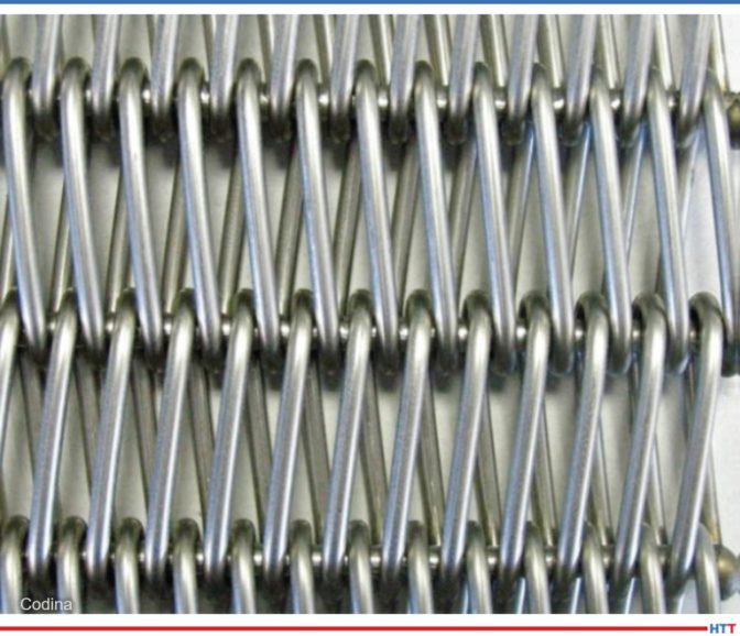
“Because the parts can be large or in baskets during the sintering (specifically irons, stainless steels) and brazing (silver, copper, nickel) processes, it is recommended that balance or double balance weave (models AE or AE-A) with just one rod inside one spiral be used. The basic material recommended is AISI 314. By the way, in the EU, the model B1ES is popular for brazing because it’s stronger and allows heavy loads on the mesh belt.” Escura added.
Photo Credit: Codina
Explain the “vocabulary” of belts:
Understanding the mesh belt lingo is critical for achieving successful results.
Heat Treat Todayasked, What about the types of belt weaves (open versus closed weaves), upturned edges — when/why are they recommended, and why are certain alloys (e.g., 316 SS) such a popular choice for general purpose belts? Escura responded, “The closed weave belts are used for small products like fasteners. Open weave belts are used for larger products.” He continues, “The material content, for heat treatment in general, needs to be high in nickel and chromium to be strong enough to resist high temperatures and oxidation.”
What is the typical belt life for processing running in the 1600°F–1800°F temperature range in a nitrogen or nitrogen/hydrogen atmosphere? Escura weighed in, “This will always depend on the process, application, and how the belt is used on the furnace. However, as a rule, the lifetime of the mesh belt can be from 6 to 12 months.”
What about the pre-conditioning (prestretching) of the belt — when is it recommended and for what applications?
Escura explained, “We do not believe this preconditioning is helpful. It’s also an extra cost. If the belt is produced properly, pre-conditioning is not necessary.”
What are a few common problems encountered when operating mesh belts?
“The main problems are belt deformations from extra load, cuts on the mesh belt due to parts stacking on the furnaces and cutting the belt. Another problem we see is lateral plates break, fall out, and come into contact with the ‘floor’ of the furnace,” Escura shared.
Are there any advances or trends in the mesh belt world that you’re excited about? What is one thing that you believe is vital for people to know about mesh belts?
Escura concluded, “We are excited about looped edges instead of welded edges terminations. These looped edges prevent the breaking of the welding, and belts can last longer in sintering and brazing applications.”
Mesh belt furnaces are the workhorse of the heat treating industry. With constant pressure to enhance performance and develop quality products, mesh belt furnaces are keeping up with the demand. In this article written by Tim Donofrio, vice president of Sales at CAN-ENG Furnaces International Limited, discover the ways mesh belt furnaces are addressing demands for innovation and quality.
This Technical Tuesday article appeared in Heat TreatToday’s February 2022 Air & Atmosphere Furnace Systems print edition.
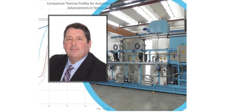
Tim Donofrio Vice President of Sales Can-Eng Furnaces International Source: Can-Eng Furnaces International Ltd.
Introduction
Manufacturers of high volume, high strength metal components constantly face increasing pressures to improve and develop enhanced performance and quality products while simultaneously addressing cost pressures placed upon them. The quality products include cold-formed automotive fasteners and clips, construction nails and screws, cutting and timing chain products, drive system gears, and bearing components, to mention a few. These reference components all require different types of heat treatment processes that impart a unique thermal profile which results in making the component stronger, tougher, more flexible, resistant to wear and corrosion, and improves the overall life of the component.
Mesh Belt Furnaces — Background
Mesh belt furnaces are synonymous with high volume heat treatment of formed, forged, and machined metal components that require soft handling methods to prevent part damage during processing. Furthermore, these systems are well equipped with features that reduce the opportunity for part mixing and contamination within the system. Modern mesh belt furnaces have been put into production around the world to achieve capacities from 100 lb/hr to 7000 lb/hr. Manufacturers today often favor higher capacity heat treatment systems as they offer more efficient returns on investment over lower capacity systems. The heat treatment processes ideally suited for mesh belt furnace systems include neutral hardening, marquenching, austempering, light case carburizing, carbonitriding, carbon restoration, normalizing, and tempering. In most cases, these processes include a multi-step process which involves heating the product to austenitizing temperatures under a reducing or carbon rich atmosphere, followed by an automatic transfer for drop from the furnace belt conveyor into a liquid quench conveyor system where the material transformation takes place. Quench systems vary in size and capacities and are custom designed around the product being heat treated. Design features may include agitation, fluid flow, and conveyor design which can greatly influence the quench speed and material transformation that results in the final physical properties achieved through quenching. Mesh belt heat treatment systems can implement various quench medias that include oil, polymer, water, and molten salts.
Mesh Belt Furnaces — Benefits
Mesh belt furnace benefits have grown significantly from their earlier developments that targeted reduced part damage and part mixing potential. Today, users are exploiting the benefits associated with increased part size range processing flexibility and capability. In the early days, part processing size range was limited to parts that weighed less than 1lb and were less than 4” in length. Today, with design enhancements, users can now process a product range that includes part sections ranging from 3/16” to 1-3/8”, part lengths up to 12” long, and part weights exceeding 2.5lbs each. This increased processing flexibility is made possible through the integration of modernized automated loading and transfer systems that minimize part drop heights and inertia, ensure precise loading, convey, and distribute products that protect against part damage while also ensuring dimensional stability is maintained to acceptable levels.
Additional advancements in the application and use of molten salt quenching have been recently exploited in response to the demand for low distortion and low residual stress level part processing. These demands are largely a result of customers’ needs to engineer products that outlive and outperform previous designs. This is largely a result of recent advancements made to support the shift in transportation technology; most noticeably, vehicle electrification and increased demands of vehicle propulsion systems. This has resulted in improved austemper and martemper technologies, paving the way for new molten salt handling designs that increase the overall safety and use of the systems. Specifically, new techniques for molten salt quench agitation, distribution, and quench drop chute fluid control have greatly improved the controllability of these systems and have also greatly improved the maintainability which has traditionally been difficult for users of previous designs.
Conclusion
It is well understood that the mesh belt furnace design provides significant benefits over other continuous and batch type processing systems for processing high volume and high-quality components that require exact metallurgical properties. The benefits of this system are immense, and system customization allows for further benefits to be integrated. The benefits discussed earlier represent recent advancements made to the mesh belt atmosphere furnace system that users are enjoying today. It should be recognized that several other design benefits also include:
Electrical heating systems, natural gas, and atmosphere reduction systems as a means of reducing users’ carbon footprint
Improved temperature uniformity of systems to support the expectations of the Automotive Industry Action Group (AIAG) CQI-9 guidelines
Hybrid quenching systems that allow for greater processing flexibility and sophisticated Industry 4.0 diagnostics, reporting and data archiving of equipment conditions, and process and product processing attributes
In closing, there are many options available to manufacturers requiring heat treating processes; therefore, the benefits of the mesh belt atmosphere heat treatment system should be strongly considered when seeking out the lowest cost of ownership for manufacturing processes.
About the Author:
Tim Donofrio, vice president of Sales at CAN-ENG Furnaces International Limited, has more than 30 years of thermal processing equipment experience. Throughout his career, he has held various positions within the custom engineered forging, commercial heat treating services, and custom engineered heat treating equipment industries.
Contact Tim at tdonofrio@CAN-ENG.com or (905) 380-6526.
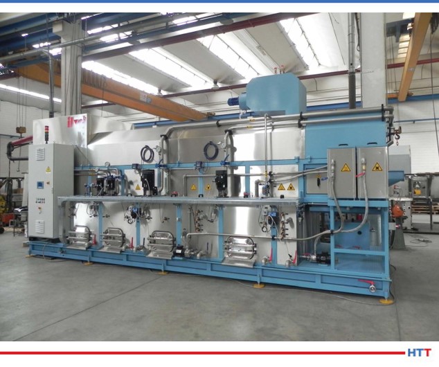
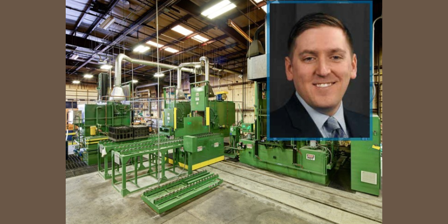
For Ovako, a centuries old manufacturer of engineering steel, innovative approaches to producing their product has taken the form of electrifying their roller hearth furnaces over the course of the past decade.
The process of converting to electric heating began in 2014, each furnace installed with up to 86 Tubothal® metallic heating elements from Kanthal. Now, 14 roller hearth furnaces are electrified. The estimated CO2 savings is around 1,400 to 2,000 tons per year per furnace.
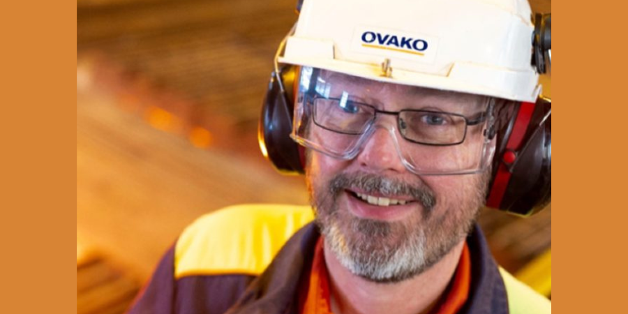
“[In] our heat treatment shop in Hofors,” shares Anders Lugnet, a furnace technology specialist at Ovako (pictured above), “we originally had around 450 gas burners, and there was always a problem somewhere in one of them. Since replacing them with 300-odd Tubothal® elements, the daily maintenance is simply not there. Occasionally, an element needs to be replaced, but it is nothing compared to the way it was.”
He continues that, previously, NOx and CO2 emissions were problematic. But with green electricity, emissions are zero, and with no flue-gas losses, total efficiency has improved significantly.
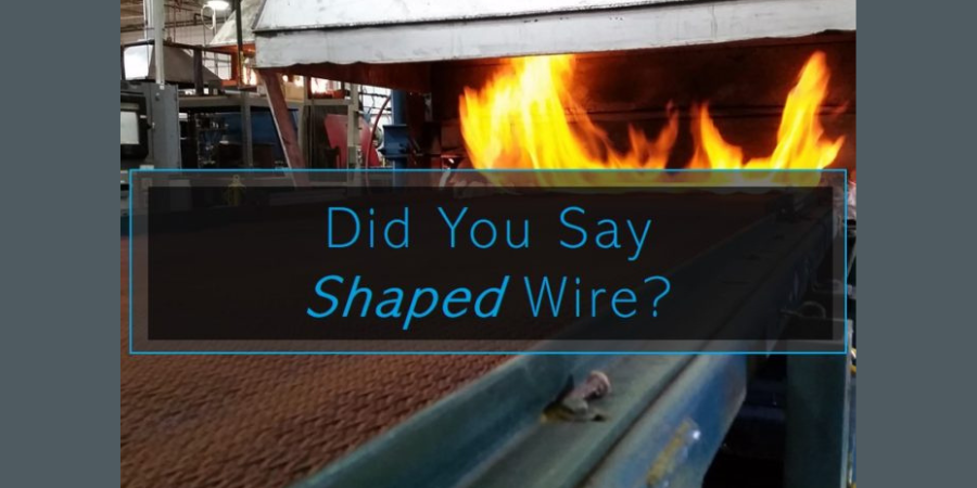
Engineered geometry increases strength, decreases stretch, and withstands thermal cycling.
For today’s Technical Tuesday, we are sharing an original content article on how innovative design of wire for mesh belts in heat treat can reduce costs to heat treaters. Technical writer Del Williams writes, that though it seems that manufacturers regard the “periodic replacement of wire belting simply a cost of doing business, innovative alternatives have been developed that can significantly prolong its life and drive down operational cost.” Read on to learn more!
Engineered geometry increases strength, decreases stretch, and withstands thermal cycling.
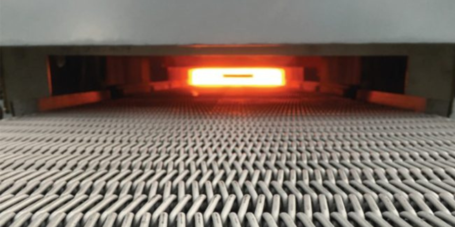
Whether for automotive, aerospace, or heavy equipment, manufacturers using heat treatment – which can reach temperatures up to 2400°F and vary from a few seconds to 60+ hours – need conveyor belting that can withstand the rigors of the process. However, traditional round balance weave wire belting has changed little in 100 years and often requires annual replacement, causing costly production downtime.
Heat treating is essential to improve the properties, performance and durability of metals such as steel, iron, aluminum alloys, copper, nickel, magnesium, and titanium. This can involve conveying to hardening, brazing, and soldering, as well as to sintering furnaces, carburizing furnaces, atmosphere tempering furnaces, and heat processing in annealing and quenching furnaces. Parts treated can range from bearings, gears, axles, fasteners, camshafts and crankshafts to saws, axes, and cutting tools.
Heat treat-grade balance weave belts – made of temperature-resistant stainless steel or other heat resistant alloys, suitable to be run on a conveyor with friction drive – can cost thousands of dollars, depending on the dimensions and quality. So, even though wear and premature replacement seems inevitable, such wire belting should not be considered a low-cost consumable. While many manufacturers using heat treating consider periodic replacement of wire belting simply a cost of doing business, innovative alternatives have been developed that can significantly prolong its life and drive down operational cost.
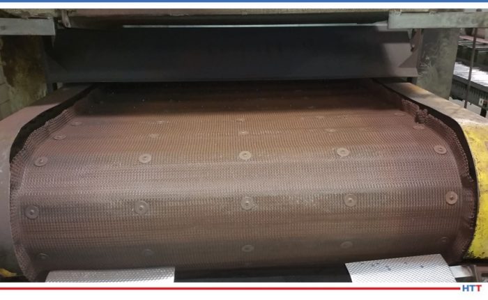
Conveyor belting for heat treating process Source: Del Williams
Although heat resistant wire belting is available, repeated thermal cycling between heating, soaking, and cooling while carrying substantial loads can continually weaken its structure until it fails. The greater and more frequent the temperature fluctuations in heat treatment steps, the shorter the wire belt’s usable life becomes.
In addition, on conveyor belts, belt stretch accelerated by heat and dynamic loading forces on the belt, is typically the main cause of breakage and failure.
Fortunately, industry innovation in the form of engineered, “shaped” wire belting has minimized these challenges. The design vastly prolongs usable life with increased strength and decreased stretch, which dramatically curtails replacement costs and production downtime.
This approach can also help to extend the longevity of wire belting used with increasingly popular powder metal parts, particularly sintered parts that may be heat treated to enhance strength, hardness, and other properties. In such cases, powder metal serves as a feed stock that can be processed into a net-shape without machining.
Resolving the Core Issues
Although conventional round wire belt has been the industry standard for generations, the geometry of the wire itself contributes to the problem.
Traditional round wire belt and even top-flattened wire belting is prone to belt stretch and premature replacement, particularly under high heat treatment temperatures. In testing, typical round and top flattened conveyor wire belt have been observed to stretch approximately 7%.
Even though many producers of conveyor wire belting simply import semi-finished product and finish it domestically, at least one U.S.-based manufacturer has gone to the root of the problem.
“Shaped” wire is designed to provide more strength in the wire belt of a given diameter so it can better withstand high heat processing conditions. This significantly prolongs its usable life.
As an example, one engineered wire belt, called Sidewinder, by Lancaster, PA based Lumsden Belting, compresses and expands wire so it is taller than it is wide with flat sides.
To begin with, the patented side flattened wire’s “I-beam” design provides 3 times greater structural support for heat treated parts compared to standard round wire. The added height of the wire also provides a longer wear life without needing heavier wire. Together, the design limits belt stretch to only 1-2%. This minimizes the potential for damaged belt. Minimal belt stretch also helps the conveyor belt to track straighter, improving production throughput with less required maintenance.
The design significantly extends the usable life of wire belt conveyors used in a variety of heat treat processes. This ranges from hardening, brazing, and soldering to sintering, carburizing, and atmosphere tempering furnaces.
It is also prolonging wire belt conveyor life in secondary powder metal processes used to improve hardness and other mechanical properties. In this vein, it could be utilized in a mesh belt sintering furnace, where compacted parts are placed in a controlled atmosphere and heated. It could also be used in processes such as quench and temper, case carburizing and induction hardening.
When heat treatment is used for hardening, followed by rapid cooling submerged in a medium like oil, brine or water, the shaped wire belt also enhances the open area for the same gauge wire. This reduces residue build up and eases cleaning, while minimizing drag.
Although the cost of the shaped wire belt is slightly more than traditional round wire, for manufacturers relying on heat treatment the gains in lifespan and production uptime can provide a speedy ROI.
About the Author: Del Williams is a technical writer based in Torrance, California. Images provided by the author.
Tim Donofrio Vice President of Sales CAN-ENG Furnaces International Limited Source: Can-Eng Furnaces International
Manufacturers of high volume, high strength precision automotive fasteners have constantly faced increased product quality standards, delivery and price pressures over the last decade. These pressures force manufacturers to seek new developments and creative methods for improving their long-term competitive positions.
This Technical Tuesday article by Tim Donofrio, vice president of sales at CAN-ENG Furnaces International Limited, will discuss two developments of mesh belt heat treatment systems – innovative tempering and dephosphating systems – that have been successfully integrated and exploited by manufacturers to maintain their competitive position.
Heat TreatToday first published this Original Content article in the Air and Atmosphere 2021 print magazine. Access the digital version of the magazine here. Contact Karen Gantzer for more information on how to contribute to future editions.
Introduction
Methods for heat treating threaded fasteners have evolved significantly over the last 20 years. Earlier versions of low-capacity shaker hearth, rotary hearth, and plate belt systems have now become extinct in favor of modern, highly efficient, continuous soft handling mesh belt heat treatment systems.
Figure 1. Mesh belt fastener heat treatment system Source: Can-Eng Furnaces International
Today’s mesh belt fastener heat treatment systems (Figure 1) integrate soft handling techniques that use bulk dunnage unloading and sophisticated metering systems. These metering systems uniformly distribute fasteners across the conveyor width, avoiding any inconsistent loading that could vary the heat-up and soak times which can impact the fasteners’ mechanical properties distribution. Fasteners are conveyed through various washing, austenitizing, quenching, tempering, and post-treatment soluble oil processes, while carefully controlling critical processing parameters that ensure compliance to DIN EN ISO-898 fastener manufacturing standard and, more recently, Automotive Industry Action Group (AIAG) CQI-9 heat treatment system assessments.
With the integration of soft handling conveyors and low inertia part transfers, modern mesh belt furnaces can significantly reduce the opportunity for part damage and the likelihood of part mixing. Further system efficiencies are realized through external furnace load preparation, allowing for precise presentation of fasteners to the conveyor belt, resulting in minimal empty belt gaps between lots for part traceability integrity.
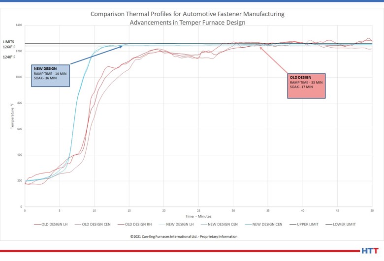
Figure 2. Comparison of automotive fastener temper furnace thermal profiles following integration of technology advancements Source: Can-Eng Furnaces International
Temper Furnace Uniformity Improvements
With increased quality objectives placed upon fastener manufacturers, furnace systems must be more and more precise. One of the most critical steps in the fastener heat treatment process is tempering, which is performed after austenitizing and quenching. Tempering is performed to increase iron-based alloy toughness, resulting in the reduction of excess hardness that occurs after subjecting the fastener to temperatures below the critical temperature for a defined period of time required for transformation. As quality restriction limits are imposed, so is the need to reduce the product temperature variation to meet the desired metallurgical and mechanical properties distribution.
With advancements in tempering furnace design, modern high capacity (+6000 lbs/hr) mesh belt temper furnaces can achieve product temperature uniformities of ±10°F or better, which is half of the allowable temperature uniformity survey (TUS) limits set out in AIAG CQI-9 assessment at ±20°F for continuous tempering furnaces (Figure 2).
These improvements in performance are made possible through the use of modern computational fluid dynamic (CFD) modeling tools. CFD modeling gives engineers the ability to conduct higher level analysis and optimization of the furnace’s forced recirculation and heating systems, internal furnace geometry, and product-to-airflow relationship.
Today, users of modern temper furnaces enjoy design improvements that increase the overall process reliability, while also exceeding the quality expectations of their customers.
Integration of Dephosphate Removal Systems
For a long time, washers integrated into continuous heat treatment systems have been considered to have companion equipment status, with not much attention paid to their product quality and total cost of ownership. The importance of washer design is currently changing, mainly due to a desire to protect furnace internal components, increase uptime, and improve the quality of the final product.
Washer design configurations include rotary drum, belt, and batch bin systems. For the purpose of this discussion, we will focus on the continuous rotary drum and belt washers for integration with high-capacity mesh belt fastener heat treatment systems (Figure 3). Both systems, if properly designed, can provide suitable performance, with each system providing enhanced features depending upon the fastener size and performance expectations. Careful consideration should be taken during the application review process to identify the configuration that best suits the range of products that will be processed.
Most modern manufactured fasteners are mechanically formed from carbon and alloy steel coils and are normally coated with a phosphate lubricant which is applied to reduce cold forming friction and increase tooling life and part quality. It is widely understood that DIN EN ISO 898 Part 1, Class 12.9 requirements for fasteners specifies that phosphate lubricants be removed prior to heat treatment as phosphate elements can diffuse into the austenite during the heat treatment process and form delta ferrite, which can lead to fastener brittleness and crack propagation failures.
Figure 3. High-capacity in-line rotary dephosphating system Source: Can-Eng Furnaces International
A recent trend in the industry is the increase in demand for integrated inline pre-heat treatment dephosphating systems. Although not a new requirement to the North American fastener market, more demand has recently been recognized largely due to increased demand for 12.9 strength class fasteners and increased localization of European automotive fasteners (Volkswagen/Audi), who specify strength class 10.9 and greater be dephosphated before heat treatment.
To satisfy these demands, modern heat treatment manufacturers are often integrating inline continuous dephosphating capability as part of their pretreatment strategies. The aqueous chemical removal of phosphate can be by acid or alkaline, however due to the risk of hydrogen-induced brittle fracture, the alkaline processes are preferred. Pretreatment wash systems implement a multi-stage process that includes:
Oil removal & rinse
Dephosphate
Rinse 1
Rinse 2
Drying
Careful consideration must be taken to guarantee wash solutions are completely removed and fasteners are properly rinsed prior to entry into the high temperature furnace to ensure protection of the furnace internals and product quality concerns.
The fasteners are conveyed either by independent conveyors or continuous rotary drums that transport fasteners through each stage of the washing and dephosphating process. Careful consideration and control of wash solution concentration, solution circulation, product dwell time, solution temperatures, and avoidance of contamination is integrated into the equipment design as it is paramount to successful dephosphating integration and final product quality.
The effectiveness of the removal of phosphate is determined by colorimetric analysis, also known as the “blue test.” In this test, a defined quantity of product with a known surface area is immersed into a chemical solution, which will react with any residual phosphate present to form a blue color. The intensity of the color is proportional to the amount of phosphate present.
The effective removal of the phosphate layer prior to the heat treatment is critical to the final fastener quality. Modern dephosphating systems, when properly integrated with the pretreatment and heat treating system, can provide the manufacturer with improved processing flexibility and product quality performance at the lowest cost per pound to process.
About the Author: Tim Donofrio, vice president of sales at CAN-ENG Furnaces International Limited, has more than 30 years of thermal processing equipment experience. Throughout his career, he has held various positions within the custom engineered forging, commercial heat-treating services, and custom engineered heat treating equipment industries.
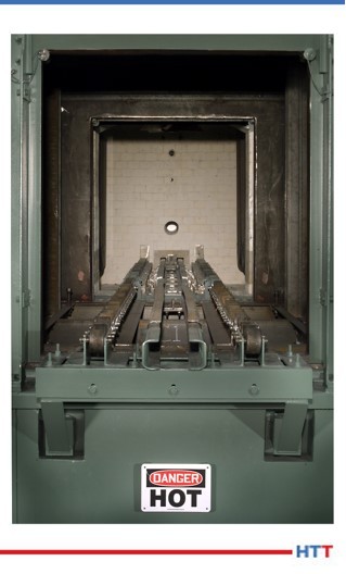
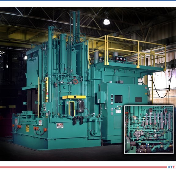
Considerable investment is made when purchasing a batch integral quench (BIQ) furnace. These popular furnaces need specific care and maintenance to keep them in prime operating condition. In this informative article by Ben Gasbarre, president of Industrial Furnace Systems at Gasbarre Thermal Processing Systems, learn how you can protect your BIQ from avoidable downtime.
This original content article appears in Heat TreatToday’s Air and Atmosphere’s February 2021 magazine. When the print edition is distributed, the full magazine will be accessible here.
Ben Gasbarre President, Industrial Furnace Systems Gasbarre Thermal Processing Systems
The batch integral quench furnace, or sealed quench furnace, is one of the most popular pieces of equipment in the heat treating industry. The core benefit is its versatility as it can easily adjust to changes in load weight, configurations, and heat treating processes. This makes
it a highly efficient and profitable piece of equipment for both captive and commercial heat treaters.
With all the good that is done in these furnaces, the downside comes in the maintenance of the equipment. By nature, these furnaces are hot, dirty, and have many moving parts, including multiple doors, load handlers, elevators, fans, quench agitators, and pumping systems; this furnace has it all! Although there are many areas of an integral quench furnace, understanding the subassemblies and having a good maintenance program can ensure the equipment operates safely and maintains its highest level of performance year after year.
Maintenance Safety
The discussion on maintenance of any piece of equipment begins and ends with safety. Prior to any work being done on the equipment, safety measures need to be considered based on the work being performed. Certain maintenance activities must be completed while the equipment is in operation; in these cases, proper personal protective equipment must be considered for work being done around hot surfaces, high voltages, elevated work, and potentially hazardous gases. If work is necessary while the equipment is offline, additional safety procedures must be followed, including lockout/tagout of all major power sources, special atmospheres, and natural gas supplies to the furnace.
Integral quench furnaces are considered confined spaces. Prior to entry into the quench vestibule, furnace chamber, and even quench pit, confined space procedures must be followed; hard stops must be in place for doors and elevators. Technicians need to ensure proper oxygen levels and air circulation prior to entry. The buddy system is always recommended when someone is entering the furnace. Prior to returning the furnace to operation, it is important to ensure all necessary safety and maintenance equipment has been removed, all supply lines are receiving designed gas pressures, and proper startup procedures are followed.
For furnace safety during shut down periods, it is wise to review furnace interlock systems and safeties to ensure proper operation. This includes items such as high-limit controllers, solenoid valves, burn off pilots, and other components critical to emergency situations. Additionally, per NFPA 86 requirements, valves and piping should be leak-checked periodically.
Reporting and Metrics for Optimum Performance
Image Source: Gasbarre Thermal Processing Systems
While Industry 4.0 is a popular concept in today’s manufacturing environment, the basic concepts behind the technology are what is important to any good maintenance plan. First, having an asset management system that enables engineers, operations, and maintenance personnel to access maintenance records is critical to ensure they can troubleshoot issues and perform maintenance activities more efficiently. Asset management tools are readily available and can range from well-established cloud-based software systems to simple Excel spreadsheet records. Ensuring important information, such as alloy replacements, burner tuning, or control calibration information, can help operations and maintenance personnel as they plan and assess future equipment needs.
The second concept is preventive or predictive maintenance plans. While these are not interchangeable concepts, the goal of implementing either is to reduce the likelihood of significant unplanned downtime, which can be costly to an organization. Preventive maintenance is a schedule of planned maintenance activities on a piece of equipment using best practices that give the best chance to catch a problem before it arises.
Predictive maintenance uses data and analytics from equipment operations that can be used to predict when problems are likely to occur. There are considerations for either approach, and the evaluation criteria for preventive versus predictive maintenance plans could be an article in and of itself.
Integral Quench Furnace Maintenance
As stated previously, breaking the furnace down into a series of subassemblies is the easiest way to develop an overall maintenance plan for equipment that has many sections and components. Discussed items will include mechanical assemblies, the heating system, the filtration system, atmosphere controls, temperature controls, and furnace seals. Each has its own importance to ensuring reliable equipment performance.
Mechanical Assemblies
Typical load transfer system alignment.
The mechanical system includes the load transfer system, recirculation fans, quench agitators, door assemblies, and elevator system. There are many exterior items that can cause abnormal equipment operation, including position sensors, rotary cam switches or encoders, and proximity switches, that if not operating properly can interrupt or cause failure within the furnace. Position settings should be logged for future reference, and sensors should be inspected regularly. Belts that may be used on recirculation fans and quench agitators should be inspected regularly for damage and excessive wear. Vibration of these items should be monitored as excess vibration can be an indication of damage or wear to the fan or agitator bearings, shaft, or blades.
The largest item of concern in this system is the alignment of the load transfer system. Unsuccessful load transfer due to misalignment or obstruction can cause significant furnace damage and create unsafe conditions within the furnace. Internal alloy components should be evaluated for integrity and alignment every six to twelve months. Elevator alignment should be reviewed to ensure smooth operation during the same period. Frequent visual inspection through sight glasses, quench time monitoring, and motor load data can give valuable information of future potential transfer issues within the furnace.
Heating Systems
Whether your furnace is gas or electrically heated, well-maintained systems can have significant impact on the operating efficiency of a furnace. For gas-heated systems, proper burner tuning and combustion blower filter cleaning can ensure optimum gas usage and can also improve radiant tube life. Burners, pilots, and flame curtains should be cleaned at least once or twice a year to ensure proper performance.
Electrically heated systems typically require less general maintenance and have fewer components that are susceptible to failure. Regular checks of heating element connections and electrical current resistance can help to identify upcoming element failure.
The largest and most critical components of reliable process performance are the radiant tubes. A crack or leak in a radiant tube can cause part quality issues. Changes in your furnace atmosphere gas consumption or troubles from controlling carbon potential can be signs of tube leaks. If the radiant tube failure is unexpected, it can also cause significant downtime if replacement tubes are not available. Cycle logs and run hour timers are the best metrics for preventive or predictive maintenance on radiant tubes.
Filtration Systems
Filtration systems are recommended for most integral quench applications. They help to eliminate build up and contamination in the oil recirculation system that flows through the heat exchanger and top/atmosphere cooler on the furnace quench vestibule. Filtration systems typically are comprised of a pump, dual filters, and an alarm system to alert users when it is time to change filters. Maintenance on your quench oil can vary by composition. Quarterly analysis of the quench oil performance is common. However, it is recommended to consult with your quench oil supplier to ensure safe and effective performance.
Atmosphere Controls
Integral quench furnace atmosphere systems can vary both by manufacturer and in overall gas composition. The most common being endothermic gas, nitrogen/methanol, along with options for ammonia or other process gases. Although these items may vary, maintenance remains consistent. Users need to ensure the integrity of the piping system including regulators, solenoid valves, and safety switches.
Endothermic gas lines should be cleaned out at least once or twice a year. Many furnace atmosphere problems can be traced back to endothermic gas generator issues, so it is important to have a well-maintained atmosphere generator to ensure peak performance in your integral quench furnace.
Typical integral quench furnace atmosphere system.
Recent technology allows for automatic burn-off of carbon probes and automated atmosphere sampling. However, probes should be burned off once per week if they are manual. Probes will require calibration and periodic replacement, and they can be rebuilt to like-new specifications. Controllers or gas analyzers that support carbon potential control should be calibrated quarterly, biannually, or annually depending on heat treat specification requirements.
Updates in the automotive CQI-9 specification will require calibration of all atmosphere flowmeters on a periodic basis. Users will need to be aware of this requirement and understand how their gas flowmeters should be calibrated. In some cases, control upgrades may be required.
Temperature Controls
Temperature control maintenance typically follows AMS2750 or CQI-9 specifications. This would relate to thermocouple replacement, system accuracy test procedures, and controller calibrations. Depending on the age of the equipment and specification requirement, these items may need to be done as frequently as once per quarter or annually.
Temperature uniformity surveys (TUS) follow similar specifications for frequency. However, a TUS can diagnose areas of the furnace that may need maintenance attention. Having a baseline TUS to reference will help identify changes in furnace performance. Changes to a TUS can indicate burner or element tuning requirements, an inner door leak, refractory damage, fan wear, or radiant tube failure.
Furnace Seals
Integral quench furnace seals can be a source of heartache for any maintenance technicians working to troubleshoot a furnace. Typical seal areas include the inner door cylinder rod, elevator cylinder rods, inner door seal against furnace refractory, outer door seal against quench vestibule, fan shaft(s), and an elevator seal if there is a top atmosphere cooler.
Typical sealing of cylinder shafts are glands comprised of refractory rope and grease. Greasing of these areas should be completed weekly. Outer door and elevator seals are typically fiber rope and may have adjustment built in as they wear, but ultimately will need to be replaced. Frequent inspection of these areas will help identify early issues. Using a flame wand or gas sniffer can help find leaks in unwanted locations. Small furnace leaks can cause part quality issues, and larger leaks can also create safety concerns within the furnace.
Additional Maintenance Items
Other key maintenance items include a bi-monthly or monthly burn out of the furnace heating chamber. This requires the furnace to have air safely injected into the chamber at or slightly above process temperature to allow the carbon to burn out of the furnace. Doing this process on a regular basis will help improve refractory and alloy component life as well as helping to maintain good process control.
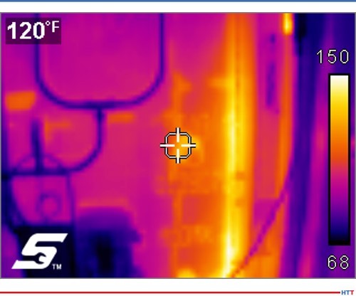
Example thermal camera image
Another helpful snapshot of furnace health is using a thermal camera to take images of the equipment. It is recommended to do this on a monthly or quarterly basis. Thermal camera images can identify hot spots on the furnace outer steel shell that may indicate refractory deterioration or a furnace atmosphere leak. Thermal images can also identify potential issues with motors or bearings on fans and agitator assemblies.
Conclusion
In the end, all furnaces have different nuances that require different maintenance approaches. This could be based on the manufacturer, types of processes being run, or utilization of the equipment. By consulting with your original equipment manufacturer or other furnace service providers, a strong maintenance plan can be developed and implemented. This can include support and training from experienced professionals on that style of furnace. Broader cost benefit analysis should be done as it relates to spare part inventories, resource allocations, frequency of preventive maintenance activities, or investments into predictive maintenance and asset management technologies and how those activities can maximize utilization of each piece of equipment.
About the Author: Ben Gasbarre is president of Gasbarre’s Industrial Furnace Systems division. Ben has been involved in the sales, engineering, and manufacturing of thermal processing equipment for 13 years. Gasbarre provides thermal processing equipment solutions for both atmosphere and vacuum furnace applications, as well as associated auxiliary equipment, and aftermarket parts and service.
All images provided by Gasbarre Thermal Processing Systems.


 Find heat treating products and services when you search on Heat Treat Buyers Guide.com


 Furnace mapping can be further developed to satisfy either CQI-9/CQI-29 or AMS2750F pyrometry standards where a two-dimensional jig is constructed to perform the temperature uniformity survey (TUS).2 Employing the plane method, a frame jig is constructed to match the furnace work zone with the necessary number of thermocouples to satisfy the furnace cross section dimensions. Temperatures recorded over the working zone are compared to the desired TUS levels to ensure that they are within tolerance as defined in the standards.