Leone

ESA Launches First Metal 3D Printer to ISS

HTD Size-PR Logo

Sometimes our editors find items that are not exactly “heat treat” but do deal with interesting developments in one of our key markets: aerospace, automotive, medical, energy, or general manufacturing.

To celebrate getting to the “fringe” of the weekend, Heat Treat Today presents today’s Heat Treat Fringe Fridayan exciting development in metal 3D printing that one might even say is "out of this world."


Rob Postema Technical Officer ESA

Metal 3D printing will soon take place in orbit for the first time. A pioneering European-made metal 3D printer is on its way to the International Space Station on the Cygnus NG-20 resupply mission which launched January 30, 2024.

“This new 3D printer printing metal parts represents a world first, at a time of growing interest in in-space manufacturing,” explains ESA technical officer Rob Postema. “Polymer-based 3D printers have already been launched to, and used aboard the ISS, using plastic material that is heated at the printer’s head, then deposited to build up the desired object, one layer at a time.

“Metal 3D printing represents a greater technical challenge, involving much higher temperatures and metal being melted using a laser. With this, the safety of the crew and the Station itself have to be ensured – while maintenance possibilities are also very limited. If successful though, the strength, conductivity and rigidity of metal would take the potential of in-space 3D printing to new heights.”

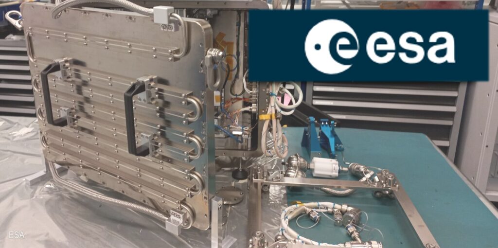
Once arrived at the International Space Station, ESA astronaut Andreas Mogensen will prepare and install the approximately 180 kg Metal 3D printer in the European Draw Rack Mark II in ESA’s Columbus module. After installation, the printer will be controlled and monitored from Earth, so the printing can take place without Andreas’s oversight.

Metal 3D printer in operation on Earth
Source: ESA

The Metal 3D Printer technology demonstrator has been developed by an industrial team led by Airbus Defence and Space SAS – also co-funding the project – under contract to ESA’s Directorate of Human and Robotic Exploration.

“This in-orbit demonstration is the result of close collaboration between ESA and Airbus' small, dynamic team of engineers,” comments Patrick Crescence, project manager at Airbus. “But this is not just a step into the future; it's a leap for innovation in space exploration. It paves the way for manufacturing more complex metallic structures in space. That is a key asset for securing exploration of Moon and Mars.”

The printer will be printing using a type of stainless-steel commonly used in medical implants and water treatment due to its good resistance to corrosion.

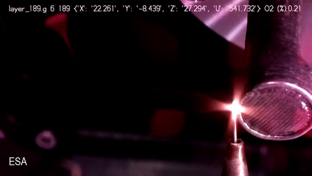
The stainless-steel wire is fed into the printing area, which is heated by a high-power laser, about a million times time more powerful than your average laser pointer. As the wire dips into the melt pool, the end of the wire melts and metal is then added to the print.

ESA materials engineer Advenit Makaya from the ESA’s Directorate of Technology, Engineering and Quality, provided technical support to the project: “The melt pool of the print process is very small, in the order of a millimetre across, so that the liquid metal’s surface tension holds it securely in place in weightlessness. Even so, the melting point of stainless steel is about 1400 °C so the printer operates within a fully sealed box, preventing excess heat or fumes from reaching the crew of the Space Station. And before the print process begins the printer’s internal oxygen atmosphere has to be vented to space, replaced by nitrogen – the hot stainless steel would oxidise if it became exposed to the oxygen.”

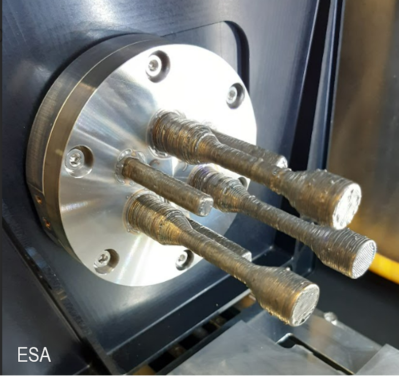
Four interesting shapes have been chosen to test the performance of the Metal 3D printer. These first objects will be compared to the same shapes printed on ground, called reference prints, to see how the space environment affects the printing process. The four prints are all smaller than a soda can in size, weigh less than 250 g per print, and takes about two to four weeks to print. The scheduled print time is limited to four hours daily, due to noise regulations on the Space Station – the printer’s fans and motor of the printer are relatively noisy.

Once a shape has been printed, Andreas will remove it from the printer and pack it for safe travels back to Earth for processing and analysis, to understand the differences in printing quality and performance in space, as opposed to Earth.

Metal 3D printer test print
Source: ESA

One reference and 0xg print, which is a part of a dedicated tool, will go to the European Astronaut Centre (EAC) in Cologne, Germany. Another two will be headed to the technical heart of ESA, the European Space Research and Technology Centre (ESTEC), where a team at the Materials and Electrical Components Laboratory awaits the samples for macro and micro analysis of the printed parts. The final print will go to the Technical University of Denmark (DTU), who proposed its shape, and will investigate its thermal properties in support of e.g. future antenna alignment.

“As a technology demonstration project, our aim is to prove the potential of metal 3D printing in space,” adds Rob. “We’ve already learned a lot getting to this point and hope to learn a lot more, on the way to making in-space manufacturing and assembly a practical proposition.”

One of ESA’s goals for future development is to create a circular space economy and recycle materials in orbit to allow for a better use of resources. One way would be to repurpose bits from old satellites into new tools or structures. The 3D printer would eliminate the need to send a tool up with a rocket and allow the astronauts to print the needed parts in orbit.

Tommaso Ghidini, head of the mechanical department at ESA, notes: “Metal 3D in space printing is a promising capability to support future exploration activities, but also beyond, to contribute to more sustainable space activities, through in-situ manufacturing, repair and perhaps recycling of space structures, for a wide range of applications. This includes in-orbit large infrastructure manufacturing and assembly as well as planetary long-term human settlement. These aspects are key focuses in ESA's upcoming technology cross-cutting initiatives.”

Thomas Rohr, overseeing ESA's Materials and Processes Section, adds: “This technology demonstration, showcasing the processing of metallic materials in microgravity, paves the way for future endeavours to manufacture infrastructure beyond the confines of Earth.”

This press release from The European Space Agency can be found in its original form here.


Find Heat Treating Products And Services When You Search On Heat Treat Buyers Guide.Com

ESA Launches First Metal 3D Printer to ISS Read More »

Box Furnace Increases Tempering Capabilities for Castings Company

Tom Schulz Sales Manager L&L Special Furnace Source: L&L
HTD Size-PR Logo

An investment castings manufacturer's heat treat department received a large floor-standing box furnace from a North American specialty furnace company. The furnace will be used as support in the client's tool and die production along with tempering of finished castings.

The L&L model XLE3436 box furnace from L&L Special Furnace has an effective work zone of 34” wide by 22” high by 32” deep. It is equipped with a direct-lift vertical door with a floor switch to activate. The cantilevered vertical door eliminates the need for the upright structure to reduce the overall height of the equipment.

Tom Schulz, sales manager at L&L, highlights the key role this will play for the heat treat department, saying that this type of furnace is the company's “workhorse when it comes to thermal processing.”

The inert blanketing gas enables the part to be heat-treated with minimal surface de-carb. A stack light indicates the furnace status via an audible and visual indicator light mounted on top of the control.

Additionally, the furnace is equipped with a pyrometry package that has reference control thermocouple ports along with corner locations to record the high and low points within the unit as indicated by the latest temperature uniformity survey.

The original press release from L&L Special Furnace is available upon request.


Find Heat Treating Products And Services When You Search On Heat Treat Buyers Guide.Com

Box Furnace Increases Tempering Capabilities for Castings Company Read More »

Exo Gas Composition Changes, Part 2: Cool Down and Use in Heat Treat Furnaces

In Part 1, the author underscored the importance of understanding the changes in gas composition through three steps of its production: first, the production in the combustion chamber; second, the cool down of gas to bring the Exothermic gas (Exo gas) to below the ambient temperature; and third, the introduction of the gas to the heat treat furnace. Read Part 1, published in Heat Treat Today’s August 2023 Automotive Heat Treat print edition, to understand what Exo gas is and to learn about the composition of gas in the first step.


Harb Nayar
Founder and President TAT Technologies LLC Source: TAT

As the author demonstrated in Part 1, Exo gas composition changes in its chemistry for heat treatment; this first step is how the gas composition changes when it is produced in the combustion chamber. The composition of reaction products, temperature, Exothermic energy released, various ratios, and final dew point are all factors that need to be considered to protect metal parts that will be heat treated in the resulting atmosphere.

Now, we’ll turn to Steps 2 and 3.

Step 2: Composition of Exo Gas after Exiting the Reaction Chamber Being Cooled Down

The two examples that follow demonstrate how lean and rich Exo under equilibrium conditions change as they are cooled from peak equilibrium temperature in the combustion chamber down to different lower temperatures (Table B). This cool down brings the Exo down to below ambient temperatures to avoid water condensation.

Example 1: Lean Exo Gas with a 9:1 Air to CH₄ Ratio

The first column highlighted in blue shows the composition of the lean Exo gas as generated in the reaction chamber with an air to natural gas ratio of 9:1. The peak temperature as generated in the combustion chamber is 3721°F. The next four columns show how the composition changes when the lean Exo gas is slowly cooled from 3721°F to 2000°F, 1500°F, 1000°F, and 500°F under equilibrium condition. The following key changes take place as the temperature of the lean Exo is lowered from the peak temperature to 500°F:

  1. Hydrogen volume almost triples from 0.67% to 1.97%.
  2. H₂O volume decreases slightly from 19.1% to 17.5%, but still is very high at all temperatures.
  3. Oxidation-reduction potential (ORP) changes as the H₂ to H₂O ratio increases from 0.035 to 0.111. At all temperatures, it is very low.
  4. CO and the CO to CO₂ ratio drop in a big way, making lean Exo from being decarburizing at higher temperatures to being highly decarburizing at lower temperatures.
  5. The percentage of N₂ remains at 70.34 at all temperatures.
  6. There is no C (carbon, i.e., soot) or residual CH₄ at all temperatures.
  7. For all practical purposes, at an air to natural gas ratio of 9:1, the Exo gas as generated is predominantly an N₂ and H₂ (steam) atmosphere with some CO₂ and small amounts of H₂ and CO.
Table B. Air to Natural Gas at 9:1 and 7:1, cooled to various temperatures

Example 2: Rich Exo Gas with a 7:1 Air to CH₄

The column under ratio of seven is highlighted as red to show the composition of the rich Exo gas as generated in the reaction chamber with an air to CH₄ ratio of seven. The peak temperature is 3182°F — significantly lower than that for lean Exo. The next four columns show how the composition changes when the rich Exo gas is slowly cooled from 3182°F to 2000°F, 1500°F, 1000°F, and 500°F. The following key changes take place as temperature of the rich Exo is lowered from the peak temperature to 500°F:

  1. Hydrogen volume almost doubles from 5.58% at peak temperature to 9.91% at 1000°F, and then it drops to 5.70% at 500°F. The overall volume of H₂ in rich Exo is significantly higher than in lean Exo.
  2. H₂O volume decreases slightly from 17.9% to 15.1%, but it is still very high at all temperatures.
  3. Oxidation-reduction potential (ORP) changes as the H₂ to H₂O ratio increases from 0.312 at peak temperature to 0.737 at 1000°F before decreasing to 0.377 at 500°F. Overall, ORP in rich Exo is significantly higher than that in lean Exo.
  4. CO and the CO to CO₂ ratio drop in a big way, making it mildly decarburizing to more decarburizing
  5. The percentage of N₂ remains at 65– 67%, which is lower than lean Exo.
  6. There is no C (carbon, i.e., soot) at any temperature. However, there is residual CH₄ at 1000°F and lower. This increases rapidly when cooled slowly below 1000°F.
  7. For all practical purposes, the rich Exo gas (at air to natural gas ratio of 7:1) generated is still predominantly a H₂
    and H₂O (steam) atmosphere, but with more H₂; hence, it has somewhat higher oxidation-reduction potential (ORP) than lean Exo and a bit higher CO to CO₂ ratio (less decarburizing than lean Exo).

In summary, rich Exo as generated in the combustion chamber differs from lean Exo as follows:

  1. It has a little less N₂ % as compared to lean Exo.
  2. It has significantly more H₂ , but a little less H₂O than lean Exo. As such, it has a significantly higher H₂ to H₂O ratio (ORP).
  3. It is decarburizing, but less than lean Exo.
  4. It has residual CH₄ at temperatures below 1000°F. Therefore, it must be cooled very quickly to suppress the reaction of developing too much residual CH₄.

Discussion

Let us take the example of rich Exo (an air to natural gas of 7:1) exiting from the reaction chamber in Table B (see column highlighted in red). The total volume is 853.3 SCFH and has H₂O at 152.4 SCFH (17.9% by volume). This is equivalent to dew point of 137°F. Its H₂ content is 47.6 SCFH (5.58% by volume). And the H₂ to H₂O ratio is 0.312.

If this were quenched to close to ambient temperature “instantly,” this composition would be “frozen,” except most of the H₂O vapor will become water. Let us assume the Exo gas was instantly quenched to 80°F (3.6% by volume after condensed water is removed). Rough calculation shows that the final total volume of H₂O vapor has to be reduced from 152.4 SCFH to about 26.0 SCFH in order to meet the 80°F dew point goal. This means 152.4 – 26.0 = 126.4 SCFH of H₂O vapor got condensed to water.

Now the total volume of Exo gas after cooling down to 80°F= 853.35 – 126.4 = 726.95 SCFH, or almost 15% reduction in volume of Exo gas as compared to what was generated in the reaction chamber.

Of course, the composition of Exo gas will not be the same as calculated above. The exact composition after being cooled down depends upon the following:

a. Cooling rate of the reaction products from the peak temperature in the reaction chamber to some intermediate temperature, typically around 1500°F.
b. Cooling rate of the gas from the intermediate temperature to the final (lowest) temperature via water heat exchangers — typically 10–20°F below ambient temperature unless a chiller or dryer is installed on the system.

Depending upon the overall design of the generator, especially how Exo gas coming out of the combustion chamber is cooled and maintained during the period of its use, the expected Exo gas composition should be in the range of the light red columns in Table B — where temperatures are between 1500°F to 1000°F — however:

  1. Total volume closer to 727 SCFH (since a major portion of H₂O was condensed out)
  2. N₂ between 74–77%
  3. Dew point between 80–90°F
  4. CH₄. between 0.1–0.5%
  5. H₂ percentage between 7–9%

Step 3: Composition of Exo Gas after Being Introduced into the Heat Treat Furnace

The cooled down Exo gas will once again change its composition depending upon the temperature inside the furnace where parts are being thermally processed.

As an illustration, let us assume the following composition of the rich Exo gas (with a 7:1 air to natural gas ratio) at ambient temperature just before it enters the furnace:

  • Total volume: 727 SCFH
  • H₂: 8% (58.16 SCFH)
  • Dew Point 86°F or 4.37% (31.77 SCFH)
  • CO: 6% (43.62 SCFH)
  • CO₂: 6% (43.62 SCFH)
  • CH₄ : 0.4% (2.91 SFH)
  • Balance N₂ (%)
  • 75.23% (546.92 SCFH)

Table C shows how the composition changes once it reaches the high heat section of the furnace where parts are being thermally treated. The column highlighted blue shows the composition of Exo gas as it is about to enter while it is still at the ambient temperature. The next three columns show the composition of the Exo gas in the high heat section of furnaces operating at three different temperatures depending upon the heat treat application — 1100°F like annealing of copper, 1500°F like annealing of steel tubes, and 2000°F like copper brazing of steel products. The H₂ to H₂O ratio decreases as temperature increases.

Other general comments on Exo generators:

  1. Generally, they are horizontal.
  2. Size ranges from 1,000 to 60,000 SCFH.
  3. Rich Exo generators use Ni as a catalyst in the reaction chamber. Lean Exo does not.
  4. Lean Exo generators typically operate at a 9:1 air to natural gas ratio. There is no carbon/soot buildup.
  5. Rich Exo generators typically operate at a 7:1 air to natural gas ratio. Below about 6.8 and lower ratios, soot/carbon deposits start appearing that require carbon burnout as part of the maintenance procedure.
Table C. Exo gas compositions in heat treat furnaces

Conclusions

A walkthrough of the entire cycle of gas production to cool down to use in the high heat section of the furnace clearly shows that as temperature changes, so does the Exo gas composition for any air to natural gas ratio.

Having a well-controlled composition of Exo gas requires the following:

  • Well-controlled composition of the natural gas used
  • Air supply with controlled dew point
  • Highly accurate air and natural gas mixing system
  • Highly controlled and maintained cooling system
  • A reliable ORP analyzer or the H₂ to H₂O ratio analyzer as part of the Exo gas delivery system.

Protecting metallic workpieces is paramount in heat treating, and in order to do this, the atmosphere created by Exothermic gas must be understood, both in the cool down phase and within the heat treat furnace. For further understanding of the good progress made in the improvement of Exo generators, see Dan Herring’s work in the reference section below.

References

Herring, Dan. “Exothermic Gas Generators: Forgotten Technology?” Industrial Heating, 2018, https:// digital.bnpmedia.com/publication/?m=11623&i=53 4828&p=121&ver=html5.

Morris, Art. “Exothermic Atmospheres.” Industrial Heating (June 10, 2023), https:// www.industrialheating.com/articles/91142-Exothermic-atmospherees.

About the Author

Harb Nayar is the founder and president of TAT Technologies LLC. Harb is both an inquisitive learner and dynamic entrepreneur who will share his current interests in the powder metal industry and what he anticipates for the future of the industry, especially where it bisects with heat treating.

For more information: Contact Harb at harb.nayar@tat-tech.com or visit www.tat-tech.com


Find Heat Treating Products And Services When You Search On Heat Treat Buyers Guide.Com

Exo Gas Composition Changes, Part 2: Cool Down and Use in Heat Treat Furnaces Read More »

An Overview of Cemented Carbide Sintering

Source: TAV Vacuum Furnaces

Cemented carbide is often used interchangeably with other terms in the industry to describe a popular material for tool production. However, the specifics of what makes up a cemented carbide, and how this material can be processed, are not so widely discussed.

In this best of the web article, discover the composition, applications, and processes involved in sintering cemented carbide, as well as how vacuum furnaces play an essential role for this material. You will encounter helpful diagrams and resourceful images depicting each step of the process.

An Excerpt:

“Hard metal, or cemented carbide, refers to a class of materials consisting in carbide particles dispersed inside a metal matrix. In most cases, the carbide of choice is tungsten carbide but others carbide forming element can be added, such as tantalum (in the form of TaC) or titanium (in the form of TiC).
The metal matrix, often referred as ‘binder’ (not to be confused with wax and polymers typically used in powder metallurgy) is usually cobalt, but nickel and chromium are also used. This matrix is acting as a ‘cement,’ keeping together the carbide particles (hence the ‘cemented carbide’ definition).”

Read the entire article from TAV Vacuum Furnaces, written by Giorgio Valsecchi, by clicking here: Sintering of Cemented Carbide: A User-Friendly Overview- Pt. 1


Find Heat Treating Products And Services When You Search On Heat Treat Buyers Guide.Com

An Overview of Cemented Carbide Sintering Read More »

This Week in Heat Treat Social Media

Welcome to Heat Treat Today’s This Week in Heat Treat Social Media. As you know, there is so much content available on the web that it’s next to impossible to sift through all of the articles and posts that flood our inboxes and notifications on a daily basis. So, Heat Treat Today is here to bring you the latest in compelling, inspiring, and entertaining heat treat news from the different social media venues that you’ve just got to see and read!

This week, we dive into innovations in several heat treat processes, take a look at some fascinating technological applications for heat treaters, tune into a conversation on batch vs. continuous furnaces, and explore an unexpectedly beautiful result of AM.

If you have content that everyone has to see, please send the link to editor@heattreattoday.com.


1. Bikes of the Future: the titanium revolution

Titanium has historically been limited as a material for bikes, despite its excellence as a material, due to its high cost and difficulty to process. Check out this post by IperionX on LinkedIn, sharing the revolutionary innovations they intend to bring to titanium processing, with applications for biking.

2. Metallurgical Moments: from Medicine, to rust removal, to atomic structure

As all heat treaters know, the world of metals is a vast one. Here are a few fascinating metallurgical moments to inform you and hopefully put a smile on your face.

The Power of Metals in MRI
Laser Cleaning: Heat Treat Potential Of The Future (Or Past?)

Did you know that the first lasers were created in 1960? They may have a futuristic look, but these devices have been around for quite a while, and their potential applications in the heat treating industry continue to grow. Check out this fascinating video from @Metallurgical Engineering on LinkedIn to get an up-close look at how lasers can be used to clean rust and perhaps streamline your heat treating maintenance in the future.

Metallurgical Art: The Structure of Metals

3. Continued Learning

Each of these posts brings an educational aspect of part of the heat treat world you may or may not be familiar with.

A Brief Overview of Quenching

HIP: What the Cool Heat Treaters Are Up To
https://www.youtube.com/watch?v=xPqvquxw9BE

4. Reading (and Podcast!) Corner

You can’t read everything, we get it. Heat Treat Today is here to recommend one informative podcast to enjoy on your daily commute, suggest a quick video on laser heat treating, and put a comprehensive article on surface treatments for automotive on your radar!

The Highly-Anticipated Sequel is Here! Tune in to Listen to Heat Treat Radio #105: Batch IQ Vs. Continuous Pusher Part 2, with Michael Mouilleseaux.
Interested in Surface Treatment? This Article from Race Engine Technology/Race Engine Suppliers magazine is for you!

In case you missed it: An overview of laser heat treating with Aravind Jonnalagadda (AJ), CTO and Co-founder at Synergy Additive Manufacturing LLC

5. AM is the Name of the Game

Additive Manufacturing (AM) is taking the heat treating world by storm, but it’s not often we get to sit back and appreciate the beauty that this technology is capable of creating. Check out this amazing gothic cathedral creating using LMM technology. Be sure to click below to see the full post.


Have a great weekend!


Find Heat Treating Products and Services When You Search on Heat Treat Buyers Guide.com

This Week in Heat Treat Social Media Read More »

Second HIP Contracted For Wallwork

HTD Size-PR Logo

Bringing forward plans by two years, Wallwork Group have signed for a second hot isostatic press. Following hot on the heels of opening their £10 million Wallwork HIP Centre, Wallwork Group is installing this HIP to meet and serve increasing demand from various manufacturers.

David Loughlin
Business Manager Wallwork HIP Centre

This second HIP from Quintus Technologies, a high pressure manufacturer with North American locations, has been contracted following Quintus completing the commissioning of the first HIP in the third quarter of 2023.

“We expected strong demand from UK castings, 3D printing, powder fabrication, and near-net-shape manufacturers. Especially, as the UK is currently under-served with hot isostatic pressing capacity,” says Wallwork HIP Centre, business manager, David Loughlin.

Adds Simeon Collins, group director of Wallwork, “Demand from customers for processing components in our first hot isostatic press has been astonishing. It is prudent to bring forward planned investment for the next HIP, knowing it will take most of 2024 to build and install. We hope to have it up and running by early 2025. Deciding to prepare pits for expansion during the first installation has proved right.”

The second HIP will be identical to the first, operating at pressures from 40 to 207 MPa (5,800 to 30,000 psi) and temperatures up to 2282°F (1250°C). It will also have the latest rapid cooling technology, as well as the capability to offer increased cycle pressures at elevated temperatures, complements engineering advances in metal 3D printing and more.

This press release from Wallwork Group can be found in its original form here.


Find Heat Treating Products And Services When You Search On Heat Treat Buyers Guide.Com

Second HIP Contracted For Wallwork Read More »

Message from the Editor: Winter

Bethany Leone
Managing Editor
Heat Treat Today

This message from Bethany Leone, managing editor at Heat Treat Today, shares some reflections on the season of winter and the opportunity this season provides to ponder the stories that inspire us towards the coming spring.

This article first appeared in December 2023’s Medical and Energy Heat Treat print edition. Feel free to contact Bethany Leone at bethany@heattreattoday.com if you have a question, comment, or any editorial contribution you’d like to submit.


Do you feel the cold of the coming winter?

Beneath the surface of earth is a realm of darkness and death, ruled by Hades. By his throne, the ever-youthful Persephone soon will join him for these winter months, as she has pledged to do each year.

Contact us with your Reader Feedback!

Perhaps you know this Greek myth: Hades, enraptured by the sweetness of Persephone, stole Persephone down to his kingdom of darkness to be his queen. While Persephone was confined below ground for what would be eternity, her mother, Demeter, went into great mourning. Side note: Persephone is a goddess. So, when we say her mother went into mourning, we mean the goddess of the harvest caused drought in the lands, weeping for her daughter.

Clearly, this could not go on. Zeus, the head god of all gods and master of the sky, intercedes on behalf of all humanity for Persephone to return to her mother. Hades agrees, after all, he’s not an evil guy; just selfish through and through, like all anthropomorphic gods. . . But before the Maiden leaves, he offers her seeds from a refreshing pomegranate, which she takes. One, two, three, perhaps six seeds she ate. She is reunited with Demeter, and all is well.

Wrong.

For in eating these seeds from the Underworld, Hades may now claim his bride to dwell with him for several months in the year.

So, each year, while Persephone is confined below ground, the Greek goddess of the harvest roams the earth in mourning, withholding grain from the land. We know that precious Persephone returns to her mother by the telltale signs of spring (yes, she is known as being the goddess of spring).

Persephone and Hades. Tondo of an Attic red-figured kylix, ca. 440-430 BC. Said to be from Vulci. (Source: ©Marie-Lan Nguyen/Wikimedia Commons)

As winter descends, this tale often breaks through my mind. Why? As a student of history, I do not believe it is true, neither does the myth cohere perfectly with my religious beliefs. But this story of six unassuming pomegranate seeds, the power of a mother’s will, and the cruel edge of mourning carries me through cold winter with thoughts of spring.

The myth, though untrue, is truer because it is not true. (For more on this tongue-in-cheek insight, read G. K. Chesterton’s chapter, “The Ethics of Elfland,” in Orthodoxy).

I enjoy telling variations of this myth to myself and turning over and over these subtle implications about life, as well as the humanizing and “just-so” element of why we may have a winter to begin with . . . well, why many of us have a true winter.

But it does not take time-tested myths to inspire. At the recent ASM Heat Treat show, I met a man who shared his passions for the industry, for serving others, for volunteering, and for making the most of 16-hour car drives to make calls to his family. While the details are a blur, the story I left with was that the reason to live was to give. While sales were important — that was his job! — this was just a part of his life story of giving.

What stories inspire you? Perhaps a successful installation of a new vacuum oil quench furnace that you supported brings to mind challenges of logistics, cooperation with culturally different people, or memories of near disasters. Were there themes of endurance, commitment to doing the hard thing so you could get smart enough to do the smart thing?

Whatever the story, remember it so whenever a “winter” in work or life comes, the themes may encourage you of a coming spring.


Find Heat Treating Products And Services When You Search On Heat Treat Buyers Guide.Com

Message from the Editor: Winter Read More »

AM Supplier Delivers Components to GA-ASI

Nicholas Mayer President of Commericial Norsk

Norsk Titanium, a global additive manufacturing supplier for aerospace-grade structural titanium components, announces delivery of flight critical aircraft structure to General Atomics Aeronautical Systems, Inc. (GA-ASI), a leading developer of unmanned aircraft systems and prime contractor to the US Department of Defense.

Under a development contract with GA-ASI’s Additive Design & Manufacturing Center of Excellence, Norsk Titanium has delivered RPD® final machined components for test and evaluation. GA-ASI will conduct destructive testing in support of specification and part development.

Said Nicholas Mayer, president of commercial at Norsk, “After an extensive collaborative qualification effort over the past few years with Norsk Titanium, GA-ASI plans to apply the qualified process to structural components within their next generation platforms currently under development, and is planning on their first flight of a critical, structurally loaded component, within the 2024-2025 timeframe.”

Norsk Titanium has recently announced qualification and production milestones in their core commercial aerospace titanium market.

This press release can be found in its original form here.


Find Heat Treating Products And Services When You Search On Heat Treat Buyers Guide.com

AM Supplier Delivers Components to GA-ASI Read More »

Skip to content