Vacuum Furnaces: Origin, Theory, and Parts
Vacuum furnaces are widely used in the aerospace and automotive industries. These furnaces are used for multiple processes including brazing, aging, and solution heat treating for countless materials. Typically, vacuum furnaces are utilized to ensure a lack of oxidation/contamination during heat treatment. This article will talk about the origins, theory, and main parts of vacuum technology and how it is used in both aerospace and automotive industries.
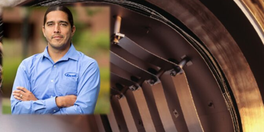
This Technical Tuesday feature was written by Jason Schulze, director of technical services at Conrad Kacsik Instrument Systems, Inc., and was first published in Heat Treat Today's December 2022 print edition.
A Brief History
Vacuum furnaces began to be used in the 1930s for annealing and melting titanium sponge materials. Early vacuum furnaces were hot wall vacuum furnaces, not cold wall vacuum furnaces like we use today. Additionally, most early vacuum furnaces did not utilize diffusion pumps.
Vacuum Heat Treat Theory

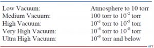
Vacuum technology includes vacuum pumping systems which enable the vessel to be pulled down to different stages through the process. Degrees of vacuum level are expressed opposite of pressure levels: high vacuum means low pressure. In common usage, the levels shown below in Figure 1 correspond to the recommendations of the American Vacuum Society Standards Committee.
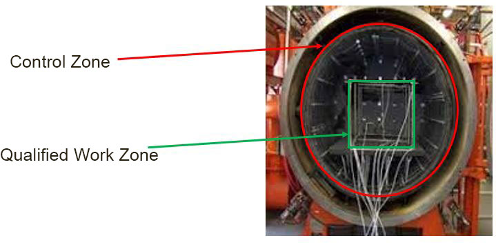
Vacuum level will modify vapor pressure in a given material. The vapor pressure of a material is that pressure exerted at a given temperature when a material is in equilibrium with its own vapor. Vapor pressure is a function of both the material and the temperature. Chromium, at 760 torr, has a vapor pressure of ~4,031°F. At 10¯5, the vapor pressure is ~2,201°F. This may cause potential process challenges when processing certain materials in the furnace. As an example, consider a 4-point temperature uniformity survey processed at 1000°F, 1500°F, 1800°F, and 2250°F. This type of TUS will typically take 6-8 hours and, as the furnace heats up through the test temperatures, vacuum readings will most likely increase to a greater vacuum level. If expendable Type K thermocouples are used, there is a fair chance that, at high readings, you may begin to have test thermocouple failure due to vapor pressure.
Source: Jason Schulze, Conrad Kacsik Instrument Systems, Inc.
Vacuum Furnace Pumping System
Vacuum heat treating is designed to eliminate contact between the product being heat treated and oxidizing elements. This is achieved through the elimination of an atmosphere as the vacuum pumps engage and pulls a vacuum on the vessel. Vacuum furnaces have several stages to the pumping system that must work in sequence to achieve the desired vacuum level. In this section we will examine those states as well as potential troubleshooting methods to identify when one or more of those stages contributes to failure in the system.
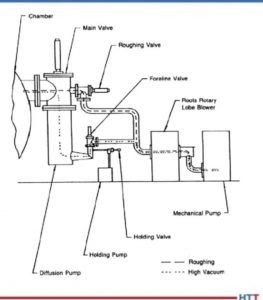
Vacuum furnaces have several stages to the pumping system that must work in sequence to achieve the desired vacuum level. Each pump within the system has the capability to pull different vacuum levels. These pumps work in conjunction with each other (see Figure 2).
Source: Jason Schulze, Conrad Kacsik Instrument Systems, Inc.
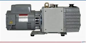
The mechanical pump is the initial stage of vacuum. This pump may pull from 105 to 10. At pressures below 20 torr the efficiency of a mechanical pump begins to decline. This is when the booster pump is initiated.
The booster pump has two double-lobe impellers mounted on parallel shafts which rotate in opposite directions (see Figure 3).
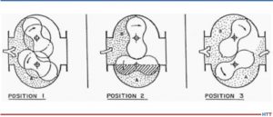
Source: Jason Schulze, Conrad Kacsik Instrument Systems, Inc.
The diffusion pump (Figure 4) is activated into the pumping system between 10 and 1 microns. The diffusion pump allows the system to pump down to high vacuum and lower. The diffusion pump has no moving parts.
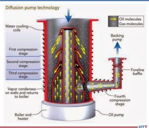
Source: Jason Schulze, Conrad Kacsik Instrument Systems, Inc.
The pump works based on the vaporization of the oil, condensation as it falls, and the trapping and extraction of gas molecules through the pumping system.
Source: Jason Schulze, Conrad Kacsik Instrument Systems, Inc.
The holding pump (Image 1) creates greater pressure within the fore-line to ensure that, when the crossover valve between the mechanical and diffusion pump is activated, the oil within the diffusion pump will not escape into the vessel.
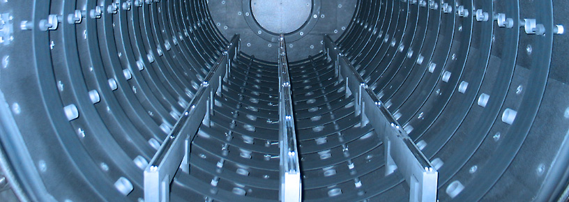
Vacuum Furnace Hot Zone Design
Source: Jason Schulze, Conrad Kacsik Instrument Systems, Inc.
Source: Jason Schulze, Conrad Kacsik Instrument Systems, Inc.
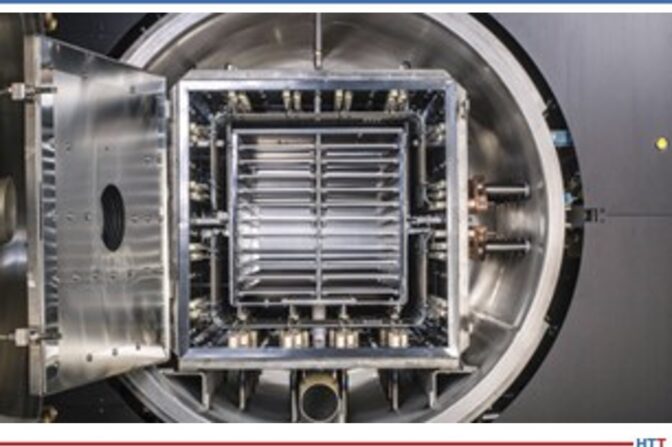
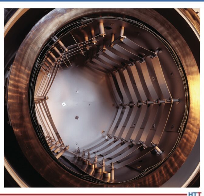
The hot zone within a vacuum furnace is where the heating takes place. The hot zone is simply an insulated chamber that is suspended away from the inner cold wall. Vacuum itself is a good insulator so the space between the cold wall and hot zone ensures the flow of heat from the inside to the outside of the furnace can be reduced. There are two types of vacuum furnace hot zones used: insulated (Image 2) and radiation style (Image 3).
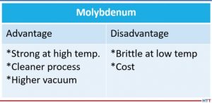
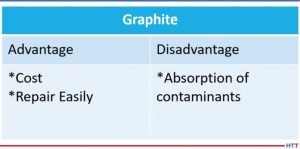
The two most common heat shielding materials are molybdenum and graphite. Both have advantages and disadvantages. Below is a comparison (Tables 1 and 2).
Source: Jason Schulze, Conrad Kacsik Instrument Systems, Inc.
Source: Jason Schulze, Conrad Kacsik Instrument Systems, Inc.
Vacuum Furnace Quenching System
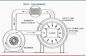
Quenching is defined as the rapid cooling of a metal to obtain desired properties. Different alloys may require different quenching rates to achieve the properties required. Vacuum furnaces use inert gas to quench when quenching is required. As the gas passes over the load, it absorbs the heat which then exits the chamber and travels through quenching piping which cools the gas. The cooled gas is then drawn back into the chamber to repeat the process (see Figure 5).
Source: Jason Schulze, Conrad Kacsik Instrument Systems, Inc.
Vacuum Furnace Trouble Shooting
In Table 3 are some helpful suggestions with regard to problems processors may have.
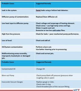
Source: Jason Schulze, Conrad Kacsik Instrument Systems, Inc.
Summary
Vacuum furnaces are an essential piece of equipment when materials need to be kept free of contamination. However, there are times when this equipment may not be necessary, and is therefore considered cost prohibitive, although this is something each processor must research. This article is meant to merely touch on vacuum technology and its uses. For additional and more in-depth information regarding vacuum furnaces, I recommend a technical book called Steel Heat Treatment, edited by George E. Totten.
About the Author: Jason Schulze is the director of technical services at Conrad Kacsik Instrument Systems, Inc. As a metallurgical engineer with over 20 years in aerospace, he assists potential and existing Nadcap suppliers in conformance as well as metallurgical consulting. He is contracted by eQuaLearn to teach multiple PRI courses, including pyrometry, RCCA, and Checklists Review for heat treat.
Contact Jason at jschulze@kacsik.com
website: www.kacsik.com
 Find heat treating products and services when you search on Heat Treat Buyers Guide.com
Vacuum Furnaces: Origin, Theory, and Parts Read More »


 and digital data collection:
 Andrew Bassett (
 “This is a topic that yields great discussions,” adds Jason Schulze (

 Gunther Braus (