One of the great benefits of a community of heat treaters is the opportunity to challenge old habits and look at new ways of doing things. Heat Treat Today’s101 Heat TreatTipsis another opportunity to learn the tips, tricks, and hacks shared by some of the industry’s foremost experts.
Today’s tips come to us from Rob Medeira and Florie Grant of Inductoheat, covering Induction Heating. This includes advice about correcting irregular part distortion and finding solutions to cracked parts.
Situation: Part is distorting irregularly after induction heat processing
Solution:
1. Check quench concentration, flow, & pressure.
2. Make sure there is proper quench uniformity.
3. Check TIR of the spindles and part holding fixtures
4. Check to ensure the part dimensions are accurate & center drills are on center.
5. Check part nest clearance when the part is cold.
6. Check to make sure the heating time is not too long.
HINTS:
· Check the part holding fixtures and spindles to ensure proper positioning.
· Some processes use a negative quench delay, quench on before heating stops, typically 0.05-0.3 seconds to improve TIR of the part.
· The part nest should not fit snug when the part is col – it will grow during the heating & warp the part.
· If the spline area has distortion or the “Go” gage is tight, try a quench delay of 0.2 to 0.4 seconds.
Heat Treat Tip #14
Cracked Parts?
(source: Inductoheat)
Situation : Cracked Parts
Solution:
1. Check parts positioning.
2. Make sure there are no unexpected hot spots; lack of rotation may be the cause.
3. Check for excessive grain growth around the crack surface area.
4. Check if quench condition is out of spec.
5. Check surface finish of part prior to hardening.
6. Apply temper ASAP.
7. Confirm & inspect steel conditions.
HINTS:
· If the part has excessive grain growth, that may lead to cracking.
· If cracking appears around hole area, then the proper chamfering might help.
· Parts out of higher carbon steels (0.55%C or higher) use higher quenching concentration & avoid surface overheating.
One of the great benefits of a community of heat treaters is the opportunity to challenge old habits and look at new ways of doing things. Heat Treat Today’s101 Heat TreatTipsis another opportunity to learn the tips, tricks, and hacks shared by some of the industry’s foremost experts.
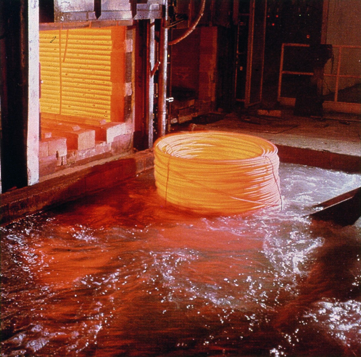
Today’s tips come to us from Quaker Houghton and Contour Hardening, covering Aqueous Quenching. This includes advice about effective filtration in removing particulates in aqueous quench systems and tips for aqueous quenchant selection.
Adding a strong magnetic filter in line after the main filtration system is an effective way to remove fine, metallic particulates in an aqueous quench system.
Submitted by: Contour Hardening
Heat Treat Tip #9
Aqueous Quenchant Selection Tips
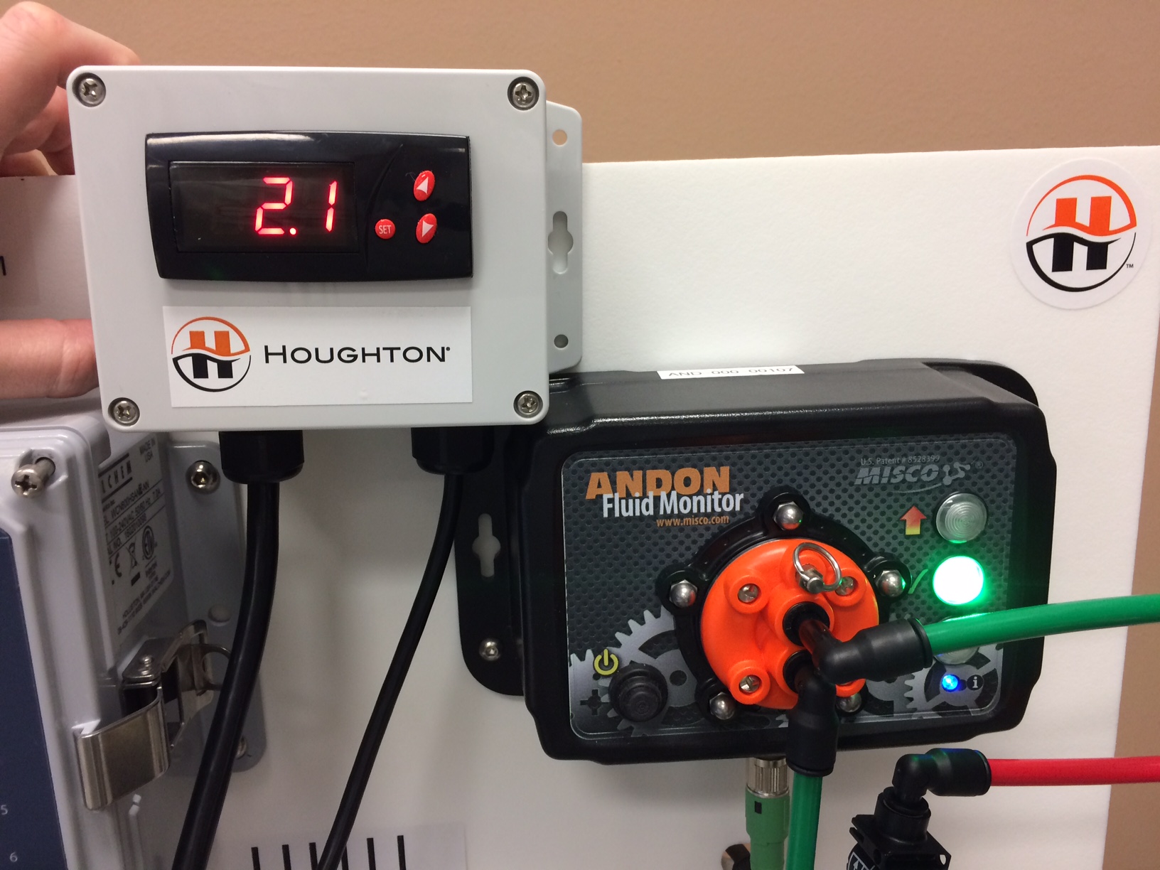
Greenlight Unit (source: Quaker Houghton)
1. Determine your quench: Induction or Immersion? Different aqueous quenchants will provide either faster or slower cooling depending upon induction or immersion quenching applications. It is important to select the proper quenchant to meet required metallurgical properties for the application.
2. Part material: Chemistry and hardenability are important for the critical cooling rate for the application.
3. Part material: Minimum and maximum section thickness is required to select the proper aqueous quenchant and concentration.
Aqueous Quenching (source: Quaker Houghton)
4. Select the correct aqueous quenchant for the application as there are different chemistries. Choosing the correct aqueous quenchant will provide the required metallurgical properties.
5. Review selected aqueous quenchant for physical characteristics and cooling curve data at respective concentrations.
6. Filtration is important for aqueous quenchants to keep the solution as clean as possible.
7. Check concentration of aqueous quenchant via kinematic viscosity, refractometer, or Greenlight Unit. Concentration should be monitored on a regular basis to ensure the quenchant’s heat extraction capabilities.
Greenlight Display (source: Quaker Houghton)
8. Check for contamination (hydraulic oil, etc) which can have an adverse effect on the products cooling curves and possibly affect metallurgical properties.
9. Check pH to ensure proper corrosion protection on parts and equipment.
10. Check microbiologicals which can foul the aqueous quenchant causing unpleasant odors in the quench tank and working environment. If necessary utilize a biostable aqueous quenchant.
11. Implement a proactive maintenance program from your supplier.
One of the great benefits of a community of heat treaters is the opportunity to challenge old habits and look at new ways of doing things. Heat Treat Today’s101 Heat TreatTipsis another opportunity to learn the tips, tricks, and hacks shared by some of the industry’s foremost experts.
Today’s tips come to us from Solar Manufacturing Inc., covering Vacuum Furnaces. This includes advice about avoiding disasters, improving vacuum furnace operations, how and when to use water, and troubleshooting.
Vacuum Furnace Disaster with High Temperature (2400F) Bake Out
Thoroughly understand the metallurgical definition of “Eutectic Reactions”. Never high temperature bake-out a vacuum furnace with the grids in it, i.e. 2400°F.
Heat Treat Tip #83
4 Tips to Improve Your Vacuum Furnace Operations
Four Suggestions for Improved Vacuum Furnace Operations
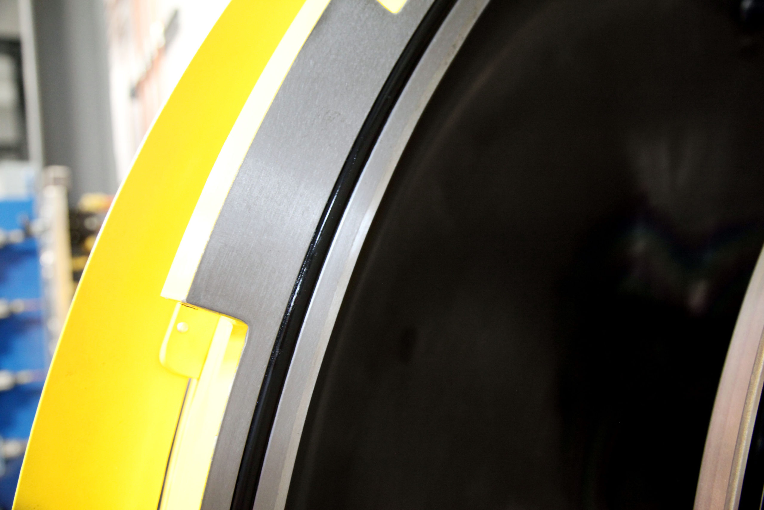
Vacuum furnace door o-ring
1. When wiping the main door O-ring and flange (which must be done every time BEFORE closing the door, especially after unloading a furnace), wipe with only your bare fingers. You risk a splinter or dirty fingers (so what, you are a heat treater), however, a bare fingertip will detect even minute scratches, nicks, or debris on an O-ring or flange. Wiping with a rag increases the likelihood that you won’t detect those conditions until it is too late. Using your bare fingers is also effective in detecting an O-ring that has become dry and in need of a new application of grease.
Thermocouples inserted into an all-metal hot zone
2. After installing a new control or overtemperature thermocouple, and especially when using a Buna N-type grommeted feedthrough, tighten the feedthrough nut quite snugly, and then retighten it after the initial pump-down, checking it again after several furnace cycles. Much of the time the grommet becomes compressed and pulled deeper into the assembly, leaving the nut loose. If this occurs, the TC could be sucked deep into the furnace during a cycle, possibly breaking when unloading the workload. Further, even a modest movement of the control thermocouple can affect the TUS results and lead to product impact concerns.
Vacuum furnace with front door bolted
3. If using an older vacuum furnace with a bolted main flange, always make sure to bolt the flange after achieving a vacuum of about -25″HG. If the door is bolted prior to sufficient evacuation, the bolts will become loose as the O-ring compresses during the pump-down portion of the process. Loose bolts could lead to a gas leak during a positive pressure quench or a vacuum leak during operation.
Recorded chart, green “pen,” of vacuum pump down record
4. During the initial evacuation of a process in a vacuum furnace, let the furnace pump until it gets to a slowly dropping rate prior to introducing partial pressure or turning on the heat. Water vapor is difficult to liberate and it can take some time, especially in a humid environment. Getting as much out as is practical prior to starting a furnace cycle is good practice in the war against discoloration.
Heat Treat Tip #84
When Water Is Your Nemesis!
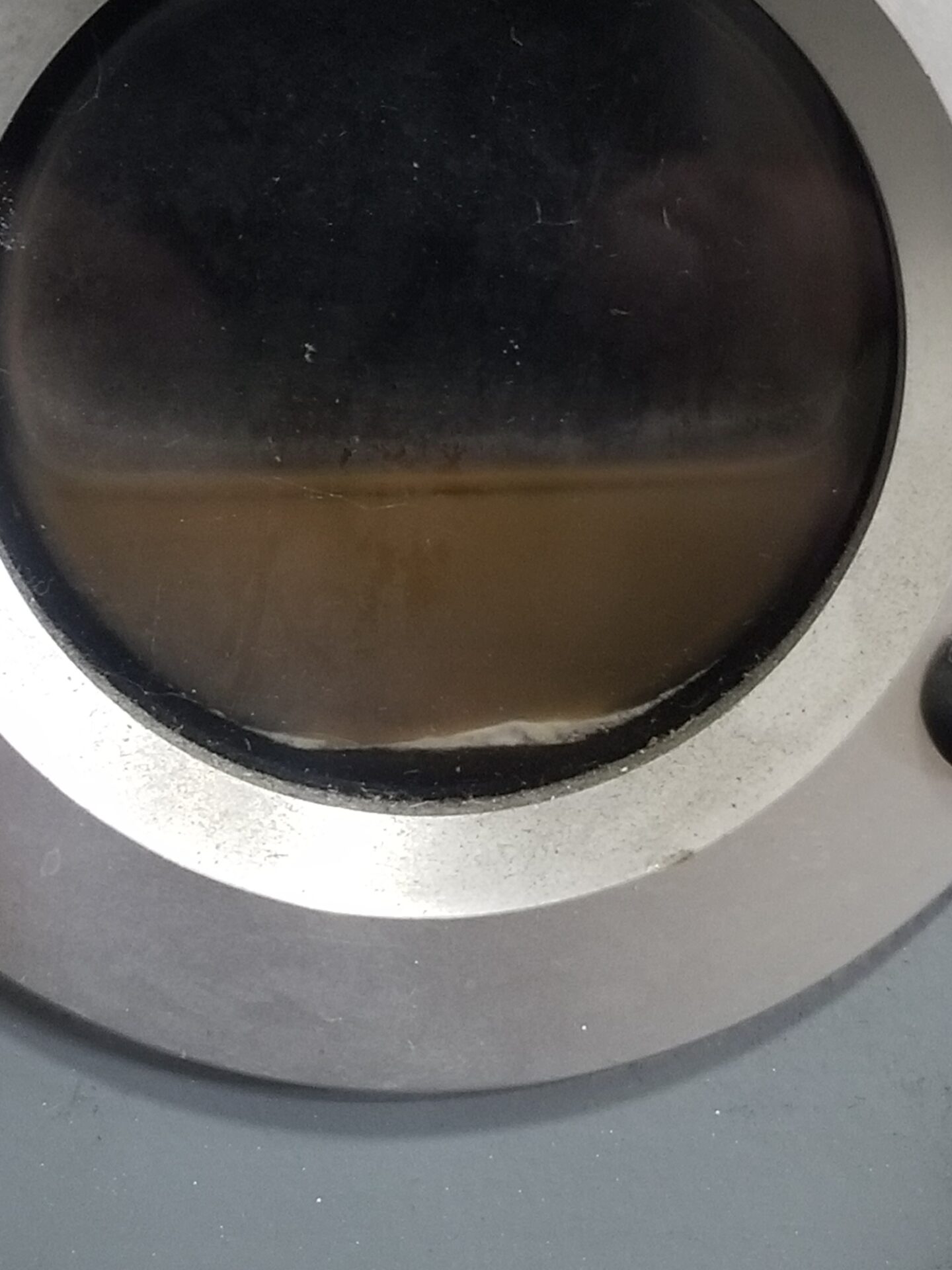
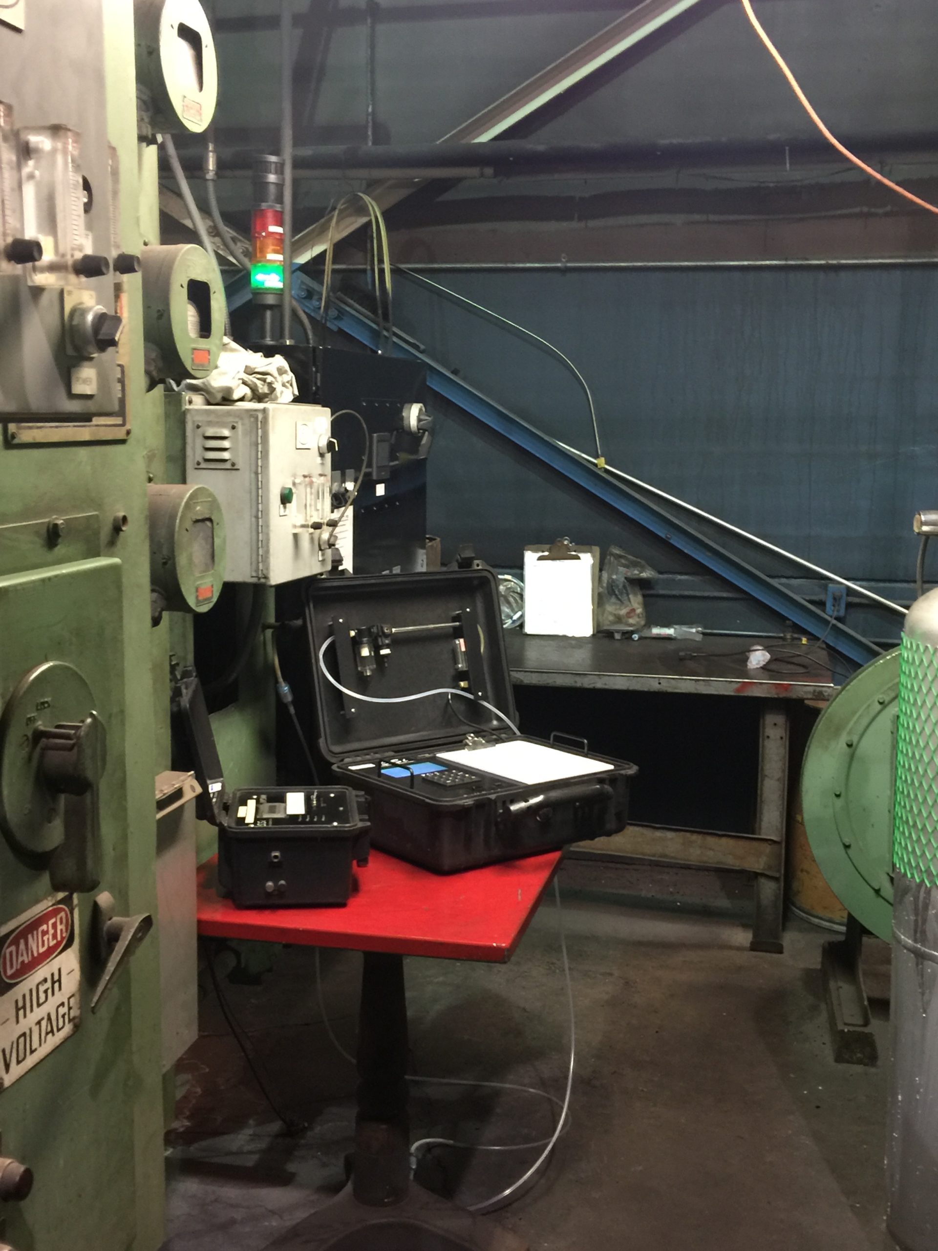
Typical Stokes 412 vacuum pump oil sight glass
On hot, humid days, moisture collects in the roughing pumps after initial cycle pump down.
• Drain as much water out as possible through the oil drain port of the vacuum pumps, usually about ½ cup of water.
• Crack open slightly, just enough for the water to drain. By cracking the gas ballast valves, this will raise the temperature of the pump and boil the rest of the water vapor off and out through the exhaust piping.
• One thing to remember with the gas ballasts open, the pumping time will be longer. So, don’t forget to close the valves after about 15 minutes.
As soon as the water is removed, only oil will remain.
Heat Treat Tip #85
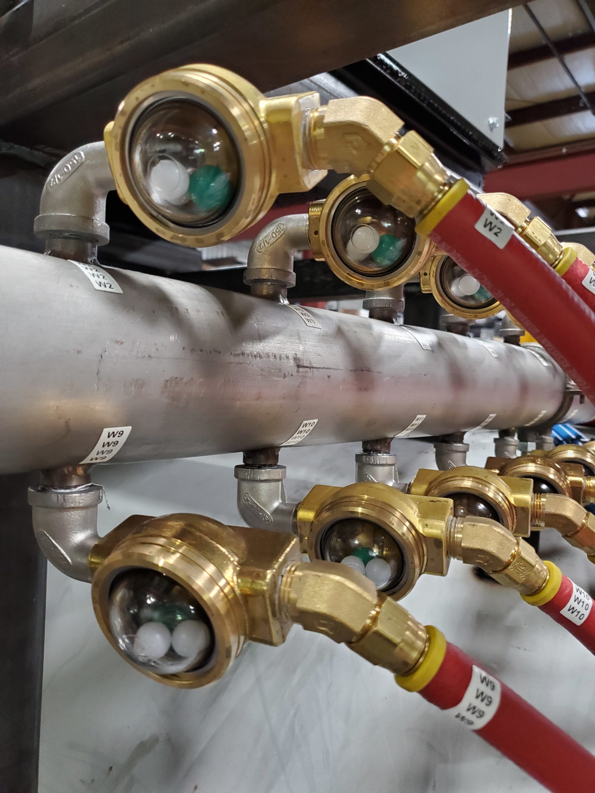
Typical vacuum chamber water quality sight meters
Cooling Water Type and Chamber Life
In the vacuum furnace world, the life of the vacuum chamber is very important. Specific care should be taken if the furnace is cooled from a domestic water supply, evaporator cooling tower, or pond water, as these sources are very rich in air and will “rust out” the chamber in less than five years. Therefore cooling water should be provided preferably from a (closed loop) air to water heat exchanger, and the cooling water quality checked monthly to the following chemistry: Water circuit flow indicators should be included to check for water turbidity, low to no particulate, in the cooling water with a site indicator type here noted.
Heat Treat Tip #86
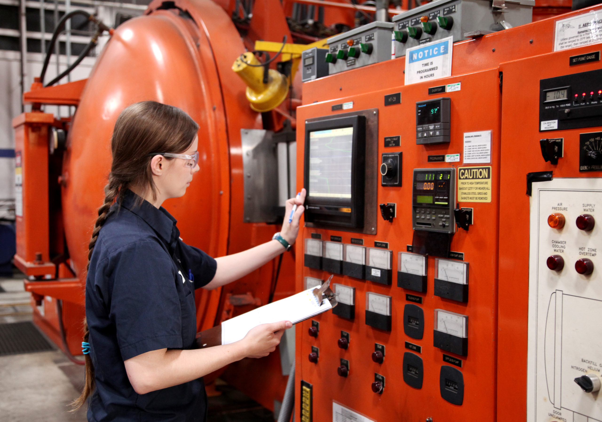
Troubleshooting Furnace Pump Down
Jessi Tatum, furnace operator at Solar Atmospheres, Inc.
If you’re having problems obtaining a vacuum level below the 500 to 50 micron range after furnace pump down, some simple analytics will help pinpoint the potential cause. Ask yourself a few questions: If it is a humid day, how long did the furnace sit open during loading, what is the size of the load in the furnace, and were the parts oily that went in? Any “yes” answers could explain slow pump down. If you rule these out, stop the cycle and watch the coarse vacuum display of the gauge. Does it immediately start going back up by tens or hundreds of microns in a very short time? If it does, you have a large leak. Did the thermocouples get in an area where the door O-ring seals? Has the door O-ring been compromised since the last load? Has some valve been left open slightly? Are any of the gas backfill valves leaking? Was something left in the furnace that shouldn’t be there? If the furnace doesn’t leak back very quickly when you stop the furnace cycle, a contaminated vacuum gauge tube or a poorly performing pumping system could be the cause. Is the booster pump running? Are the diffusion pump heaters on and pulling proper current? By following this simple regimen, you can quickly determine what resources you’ll need to assemble to further troubleshoot the problem and get that load going.
One of the great benefits of a community of heat treaters is the opportunity to challenge old habits and look at new ways of doing things. Heat Treat Today’s101 Heat TreatTipsis another opportunity to learn the tips, tricks, and hacks shared by some of the industry’s foremost experts.
Today’s tips come to us from Safety Consultant Rick Kaletsky, covering Shop Safety. These include advice on accurately labeling containers to match what is listed on safety data sheets, equipping eye fountains and deluge showers with audio and visual alarms, and updating missing or damaged bezels on gauges.
Unclear labeling of chemical materials creates a hazardous situation.
Container Clarity Counts!
Assure that container label wording (specifically for identifying chemical contents) matches the corresponding safety data sheets (SDS). Obvious? I have seen situations where the label wording was legible and accurate and there was a matching safety data sheet for the contents, but there was still a problem. The SDS could not be readily located, as it was filed under a chemical synonym, or it was filed under a chemical name, whereas the container displayed a brand name. A few companies label each container with (for instance) a bold number that is set within a large, colored dot. The number refers to the exact corresponding SDS.
Heat Treat Tip #60
Emergency eye fountains are critical, but human assistance goes far.
Alarm Your Eye Fountains & Deluge Showers
For emergency eye fountains and deluge showers, I recommend that each plumbed unit be equipped with an audio and visual alarm on a spring-loaded bypass. The purpose of the alarm is to alert others of the emergency. It is important that employees promptly respond to assist the employee who has been sprayed, splashed, or otherwise contacted by the dangerous substances. The bypass allows employees to easily test the units without setting off the alarm. If there is no bypass, employees might be reluctant to conduct the test, feeling it takes too much effort to alert all relevant persons that there is a test. As a result, an inadequacy of the flushing system could go undetected. With the bypass on a spring-loaded system, the person who conducts the test cannot fail to reset the alarm; it is reset automatically.
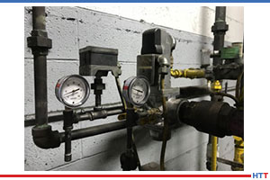
Heat Treat Tip #81
Gauge Those Gauges
It is quite common, in my experience during inspections, to find gauges that are missing bezels or have severely broken bezels. This can be a hazard if the stylus or general mechanism is damaged. I have found stuck styluses. A false reading may be given. Such a reading may result (for example) in an employee boosting air pressure, or the level of liquid in a tank or a temperature, far beyond the safe limit. I have also noted gauges where the stylus had been broken-off, and an employee merely made an assumption of what the proper “numbers” were. When conducting preventive maintenance tasks, check those gauges and replace missing or damaged bezels.
Today’s tips come to us from AFC-Holcroft, covering Thermocouples, Atmospheres, and Flow Power.
Heat Treat Tip #4
Pack Your Thermocouples
When a thermocouple is used with an open-ended protection tube, pack rope or fiber between the thermocouple and the protection tube to prevent cold air infiltration from influencing the reading.
Photo Credit: Super Systems, Inc. (SSi)
Heat Treat Tip #7
A Good Fit
If a thermocouple fits loosely in a protection tube, avoid errors by ensuring that the tip maintains good contact with the tube.
Photo Credit: Super Systems, Inc. (SSi)
Heat Treat Tip #25
Oxygen Analysis as a Cost Saver
Investing in and using an oxygen analyzer on a regular basis can provide significant fuel cost savings and, at the same time, optimize uniformity and maximize capacity.
Photo Credit: Super Systems, Inc. (SSi)
Heat Treat Tip #26
Flow Power
Pressure varies as the square of the flow. This means that to double the flow, with all else being constant, pressure must increase by a factor of 4. Also, power increases as the cube of the flow. Doubling the flow produced by a fan or blower requires an 8-fold increase in horsepower.
Heat Treat Tip #77
Puzzling Polarity?
If unsure of the polarity of a type K thermocouple, remember that the negative (red) leg is magnetic; the positive (yellow) is not.
Heat Treat Tip #94
Copper as a Leak Check
If maintaining dew point is a problem, and it’s suspected that either an air or water leak is causing the problem, run a piece of copper through the furnace. Air will discolor the copper; water will not.
Heat Treat Tip #97
Optimum Dew Point
It is much easier to produce low dew point gas in a generator (within reason) than it is to lower the dew point after the atmosphere is in the furnace using enriching gas.
Heat Treat 2019 is coming, and one of the great benefits of gathering with a community of heat treaters is the opportunity to challenge old habits and look at new ways of doing things. Heat TreatToday’s101 Heat TreatTips is another opportunity to learn the tips, tricks, and hacks shared by some of the industry’s foremost experts. The inaugural list of 101 Heat Treat Tips was published in the FNA 2018 Special Print Edition. This special edition is available in a digital format here.
Today's Technical Tuesday features 10 Tips -- all from the Vacuum Furnaces category and all supplied by the same equipment manufacturer.
Heat TreatTodayis compiling the 2019 101 Heat TreatTipslist for the fall issue to be distributed at Heat Treat 2019, the biennial show from the ASM Heat Treating Society to be held in Detroit, Michigan, October 14-17, 2019. If you have a heat treat-related tip that would benefit your industry colleagues, you can submit your tip(s) to doug@heattreattoday.com or editor@heattreattoday.com.
Heat TreatTip #24
Dirt In, Dirt Out!
Parts going into the furnace should be as clean as possible. Avoid placing parts in the furnace that contain foreign object debris (FOD). FOD on work surfaces going into the furnace will contaminate the furnace and the parts themselves. Dirty work in, dirty work out. FOD comes in many forms. Most common: oil, grease, sand in castings or grit blasting operations, and metal chips that generally originate from the manufacturing process before the parts are heat treated. It could also be FOD from the shipping process such as wood or plastic containers used to ship the parts.
Heat TreatTip #26
Solenoid valves could be the problem if helium detection fails.
When a Helium Leak Detector Doesn't Help
If an air leak cannot be found with a helium mass spectrometer, take apart the gas backfill or partial pressure solenoid valves to ensure they are clean. A small piece of debris can cause a valve to leak a process gas into the furnace that will not be found with a leak detector. Debris is often found in the valve seats when piping to the valve was disturbed in some way such as new piping or repair that stirs up contaminants in the line.
Heat TreatTip #46
O2 Analyzer Helps Ensure Gas Purity
In addition to monitoring dewpoint at the farthest location from the gas source in your heat treat facility, an oxygen analyzer is also recommended as an additional tool for monitoring gas purity. Generally, the analyzers used to measure dew point drift low over time. One may think they have a very low dew point gas, however, it could be the dew point analyzer is beginning to fail. Quarterly checks of the dew point analyzer's accuracy should be taken; some OEMs recommend replacing the sensors annually. Oxygen analyzers provide a more stable reading over a period of time and build redundancy in confirming gas purity when coupled with the dew point analyzer.
Heat TreatTip #48
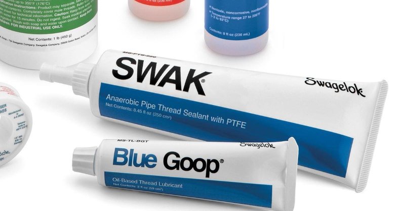
Seal Threaded Connections
SWAK from Swagelok is a great thread sealing option. (photo source: LinkedIn)
Ensure threaded connections have adequate sealing protection on them to prevent air leaks through the threads where applicable. Wipe off excess sealant once the connection is made.
SWAK from Swagelok is excellent
Apply to the male threads only, not on any other surface as it could contaminate the system the component is being installed on.
Excess SWAK can be removed with a solvent such as acetone
Finger tight first, then tighten with a wrench
After the sealant is dry (recommend 24hrs by manufacturer) do not loosen as this could break the seal once cured.
Heat TreatTip #61
Start With the Obvious
When a problem arises with the furnace, always start the troubleshooting process with the last item that was worked on. Start with the obvious; don't look for a needle in the haystack. For example, if the furnace will not pump into high vacuum and maintenance was just performed on the furnace with the pneumatic pressure valves being shut to perform that maintenance operation, the pneumatic valve to the main poppet valve on the diffusion pump may not have been re-opened, causing the diffusion pump main poppet valve to not open.
Heat TreatTip #74
Make Sure Your Gas Meets Spec
Ensure each delivery of process gas is accompanied by a certification identifying purity, oxygen content, and dew point. For example, nitrogen should be 99.998% pure, 10 ppm oxygen max, and a dewpoint no higher than -89°F. With contaminated gas or gas that does not meet the criteria above, parts processed in the furnace and subjected to the partial pressure of the gas or quenched with the gas may also become contaminated, typically in form of oxidation and/or decarburization. Generally varying purity is not a concern, however, the specific purity of the gas required needs to be conveyed to the gas supplier and a certification supporting the gas type you ordered was delivered. An accompanying certification by the gas supplier goes a long way in audits and other disputes.
Heat TreatTip #76
Specification Checklist for Vacuum Furnace Purchase
If you're planning on purchasing a new vacuum furnace, create a technical specification for the manufacturer(s) that clearly outlines the performance, functions, and accessories required on the furnace. The specifications should be reviewed by multiple departments including but not limited to engineering, quality, production, and management.
List of department sign-offs required (engineering, production, maintenance, quality)
List of parameters to be recorded (temperature, pressure, flow rate, etc.)
List of required alarms
Physical location of furnace and associated components such as control system and surge tank
Units of measurement (°F or °C, torr or Pascals, minutes or hours)
How many process gases and what type
Cooling rate requirements (This will help decide what quench pressure design furnace is required, for example, 2 bar or 10 bar.)
How many work thermocouples are required
What pre-testing verification is required for final acceptance. For example, thermal uniformity survey temperature points and tolerances, vacuum pump downtime and levels, leak up requirements, quench tests, process validation tests.
Wipe both door flanges and O-ring every time.
Heat TreatTip #84
Clean the Door—Every Time!
Wipe down the front door O-ring and both flanges every time before the door is closed to ensure there is no debris on the O-ring or flange. Over time, the debris will damage the O-ring and pit the flange causing sealing issues.
Heat TreatTip #91
Include Maintenance Team in New Vacuum Purchase Process
Include the maintenance manager in any furnace purchase decision. The manager and team are the ones tasked with troubleshooting, repair, and preventative maintenance. The maintenance manager will make sure the furnace has clear access for maintenance and replacement of major components including vacuum pumps, cooling motor, hot zone, and heat exchanger. The longer it takes to repair the furnace, the more downtime and lost revenue because the furnace is not running.
Heat TreatTip #94
A properly greased O-ring will ensure a solid, leak-free seal.
Inspect Replacement O-Rings
When replacing an O-ring, be sure the new O-ring is clean and undamaged (free of cuts, nicks, tears, or gouges) and that the splice joint is solid and true. Use a conservative amount of vacuum grease on the O-ring to ensure a tight sealing furnace. Not too much grease is needed. Rule of thumb: a light gloss or sheen, but no build-up.
If you have a heat treat-related tip that would benefit your industry colleagues, you can submit your tip(s) to doug@heattreattoday.com or editor@heattreattoday.com
During the day-to-day operation of heat treat departments, many habits are formed and procedures followed that sometimes are done simply because that’s the way they’ve always been done. One of the great benefits of having a community of heat treaters is to challenge those habits and look at new ways of doing things. Heat Treat Today’s 101 Heat Treat Tips, tips and tricks that come from some of the industry’s foremost experts, were initially published in the FNA 2018 Special Print Edition, as a way to make the benefits of that community available to as many people as possible. This special edition is available in a digital format here.
Today we continue an intermittent series of posts drawn from the 101 tips. The tips for this post can be found in the FNA edition under Industrial Gases and Combustion.
Heat TreatTip #11
Safety Shutoff Valves Can Plug
New safety shutoff valves without a manual reset lever contain filter screens that can plug with carbon and reduce endo flow. Monitor inlet and outlet pressure of the valve to prevent atmosphere issues.
While it’s very important to have adequate gas and air supply pressures for proper combustion, this alone doesn’t guarantee sufficient flow. Flow is the volume of a fluid that passes a point in a given amount of time. It can be measured in units such as ft3/hr, m3/s, etc. Flow can also be thought of as an area multiplied by a velocity. For example, area can be expressed in ft2, and velocity can be expressed in ft/s. ft2 multiplied by ft/s yields ft3/s, which is a unit of volume flow. An orifice is a device commonly used to measure flow in the combustion industry. The orifice incorporates a plate with a small hole in it. As the fluid passes through the plate, its velocity increases to compensate for the reduction in cross-sectional area in order to maintain constant volume flow.
This creates what we call a pressure drop across the orifice. Total pressure consists of both a static component and a velocity component. When a fluid is at rest, all of its pressure is static. As a fluid starts to flow, it develops a velocity pressure. This velocity pressure increases as, you guessed it, velocity increases. In order to maintain a constant total pressure, the static pressure decreases to compensate. An orifice plate has a static pressure tap located on each side of it. As a fluid passes through an orifice plate, its velocity pressure increases, and its static pressure decreases. Therefore, the static pressure on the downstream side of the orifice plate will be lower than that on the upstream side. It is this static pressure drop or differential that provides us with a direct indication of the flow rate.
When burners are rated by the manufacturer, they are tested in a laboratory environment. The flow of both gas and air are adjusted to precise values as measured by meters. The pressure drops for gas and air are measured and recorded. These values are provided to the customer so that he can duplicate the adjustments in the field. If an obstruction occurs in a pipeline, this will likely reduce the flow rate. Also, settings can and do change over time due to valve drift, ambient temperature changes, etc. Measurement of the static supply pressure alone will not provide any indication of a problem. Therefore, it’s very important to check differential pressures for gas and air periodically in order to ensure proper flow, and hence proper combustion.
During the day-to-day operation of heat treat departments, many habits are formed and procedures followed that sometimes are done simply because that’s the way they’ve always been done. One of the great benefits of having a community of heat treaters is to challenge those habits and look at new ways of doing things. Heat TreatToday‘s 101 Heat TreatTips, tips and tricks that come from some of the industry’s foremost experts, were initially published in the FNA 2018 Special Print Edition, as a way to make the benefits of that community available to as many people as possible. This special edition is available in a digital format here.
Today we continue an intermittent series of posts drawn from the 101 tips. The tips for this post come from a variety of categories but all generally address safety or cost-saving ideas.
Dr. Valery Rudnev, FASM, Fellow of IFHTSE, Professor Induction, Director Science & Technology, Inductoheat Inc., An Inductotherm Group company
Heat TreatTip #2
Avoid axle shaft cracks after induction tempering
Situation: In induction scan hardening of axle shafts, there was NO cracking occurred after scan hardening (case depth varies from 5 mm to 8 mm). Cracks appeared in the spline region after induction tempering.
Solution: Most likely, the cause of this problem is associated with a reversal of residual stress distribution during induction tempering. Reduce coil power for tempering and increase time of induction tempering. Multi-pulse induction tempering applying lower power density might also help. As an alternative, instead of modifying temper cycle, you can also try to reduce quench severity by increasing the temperature of the quenchant and/or its concentration.
When designing a vacuum furnace installation with a closed loop water system, elevate the tank and pump about 9 feet, then cage the space underneath for thermocouple storage, spares, and tools. Saves shop floor space.
IR cameras have come way down in price—for a thousand dollars, you can have x-ray vision and see furnace insulation problems before they cause major problems—also a great diagnostic tool for motors, circuit breakers, etc. (And you can spot deer in the dark!)
When SCRs are involved in the design of a new piece of equipment, questions arise. Control Concepts Inc of Chanhassen, MN, offers a 20-point design checklist to help engineers who don’t specialize in power controllers. Good reading. Search for “design checklist” at the website.
Before you specify a heat treatment, stop and consider your options. Rather than reusing an old specification, ask the design engineer to determine the stress profile, and base the hardness or case depth on real stress data. Is this complicated? Maybe. But especially for carburizing, why pay for more depth than you need, and why take the risk of inadequate strength? The 21st century is here. We have ways to help with the math. Let’s move beyond guess and test engineering methodology.
During the day-to-day operation of heat treat departments, many habits are formed and procedures followed that sometimes are done simply because that’s the way they’ve always been done. One of the great benefits of having a community of heat treaters is to challenge those habits and look at new ways of doing things. Heat TreatToday‘s 101 Heat TreatTips, tips and tricks that come from some of the industry’s foremost experts, were initially published in the FNA 2018 Special Print Edition, as a way to make the benefits of that community available to as many people as possible. This special edition is available in a digital format here.
In today’s Technical Tuesday, we continue an intermittent series of posts drawn from the 101 tips. The category for this post is Industrial Gases, and today’s tip #39 comes from Dan Herring, “The Heat Treat Doctor®”, of The Herring Group.
Heat TreatTip #39
How to Install an Ammonia System
Dan Herring, “The Heat Treat Doctor®”, of The Herring Group
One of the keys to any successful ammonia system installation in the heat treat shop is to find a supplier who is capable of providing premium grade (also known as metallurgical grade) anhydrous ammonia. This product has little or no water, which could contaminate your process. Look for a specification of 99.995% ammonia.
Once you have picked a supplier, there are several choices when it comes to ammonia storage. For the lowest product price, you should consider a tank of at least 10,000 gallons (43,000 pounds of ammonia.) This allows you to purchase full 38,000-pound tanker trucks of ammonia to reduce your supply costs. One pound of ammonia yields 22.5 cubic feet of vapor or 45 cubic feet of dissociated ammonia (75% H2, 25% N2).
In most states, you must comply with these standards if you have more than 10,000 pounds of anhydrous ammonia on site. So, you need to make sure you comply with OSHA’s Process Safety Management (PSM) and EPA’s Risk Management Plan (RMP).
The second option is to keep below the 10,000-pound threshold by installing a 1,000 gallon (4,400-pound capacity) or a 2,000 gallon (8,800-pound capacity) storage tank. Pricing for ammonia into these tanks runs about 50% higher in the smaller quantities. Even with the lower inventory, you will need to comply with OSHA 1910.111 and any applicable state, city, or county laws. It is critical to check with local agencies to make sure you are in full compliance with these regulations.
Another option for smaller usages are ammonia cylinders, but if stored inside the factory, special containment cabinets are required. Check with your ammonia supplier for the details.
With regard to the installation, in most cases, you need to pour a foundation for the tank, provide electricity to the tank for a sidearm vaporizer (used to maintain pressure in the tank since you will be withdrawing ammonia vapor to the process) and provide piping from the tank to your process. Most suppliers can lease the tank and valves/attachments for a nominal monthly fee depending on your ammonia consumption. You can also add a telemetry unit that allows your supplier to monitor your tank level via an Internet site. You will need to install a water shower near the tank and have gas masks close to the tank. It is a good idea to provide a fence around the tank if your company does not have security. Your supplier should provide hazardous awareness training for ammonia.
You can expect relatively trouble-free operation from a properly installed and well-maintained ammonia supply. Maintenance problems, other than an occasional paint job, are usually minimal but good inspection (including all valving) and frequent leak checks are mandatory. The tank should be visually inspected yearly, probably by your supplier, and the pressure relief valves should be changed every five years.
If you have any questions, feel free to contact the expert who submitted the Tip or contact Heat TreatToday directly. If you have a heat treat tip that you’d like to share, please send to the editor, and we’ll put it in the queue for our next Heat TreatTipsissue.
During the day-to-day operation of heat treat departments, many habits are formed and procedures followed that sometimes are done simply because that’s the way they’ve always been done. One of the great benefits of having a community of heat treaters is to challenge those habits and look at new ways of doing things. Heat TreatToday‘s 101 Heat TreatTips, tips and tricks that come from some of the industry’s foremost experts, were initially published in the FNA 2018 Special Print Edition, as a way to make the benefits of that community available to as many people as possible. This special edition is available in a digital format here.
Today, we offer one of the tips published under the Alloy Fabrications category.
Alloy Fabrications
Heat TreatTip #1
Allow for Thermal Expansion
When bringing furnaces to operating temperature, always be aware of thermal expansion of your alloy components. Muffles, retorts, radiant tubes all expand with heat input. These components must be free to expand within the furnace or early failure may result.
Heat TreatTip #40
Consider Corrugated Inner Covers
Inner covers are a component of the batch annealing process in the steel industry. If your inner covers are vertically corrugated, consider horizontally corrugated inner covers instead. Horizontally corrugated inner covers are repairable and, for this reason, offer longer overall life and better value.
Heat TreatTip #52
Batch Rotary Retorts — Stay Put and Stay Clean
Batch rotary retorts are positioned on furnace rollers at the front of the furnace. In time, these retorts expand until they no longer track on the rollers. Extend the life of your batch rotary retorts by using adjustable roller brackets (available from Alloy Engineering). And to keep the outlet tubes clean, use Alloy Engineering pig-tails and augers to self-clean batch rotary retort outlet tubes.


 the opportunity to challenge old habits and look at new ways of doing things. Heat Treat Today’s 101 Heat Treat Tips is another opportunity to learn the tips, tricks, and hacks shared by some of the industry’s foremost experts.