During the day-to-day operation of heat treat departments, many habits are formed and procedures followed that sometimes are done simply because that’s the way they’ve always  been done. One of the great benefits of having a community of heat treaters is to challenge those habits and look at new ways of doing things. Heat Treat Today’s 101 Heat Treat Tips, tips and tricks that come from some of the industry’s foremost experts, were initially published in the FNA 2018 Special Print Edition, as a way to make the benefits of that community available to as many people as possible. This special edition is available in a digital format here.
Today we continue an intermittent series of posts drawn from the 101 tips. The tips for this post can be found in the FNA edition under Industrial Gases and Combustion.
Heat Treat Tip #11
Safety Shutoff Valves Can Plug
New safety shutoff valves without a manual reset lever contain filter screens that can plug with carbon and reduce endo flow. Monitor inlet and outlet pressure of the valve to prevent atmosphere issues.
Submitted by Young Metallurgical Consulting
Heat Treat Tip #12
Pressure vs. Flow
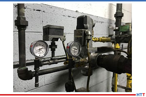
While it’s very important to have adequate gas and air supply pressures for proper combustion, this alone doesn’t guarantee sufficient flow. Flow is the volume of a fluid that passes a point in a given amount of time. It can be measured in units such as ft3/hr, m3/s, etc. Flow can also be thought of as an area multiplied by a velocity. For example, area can be expressed in ft2, and velocity can be expressed in ft/s. ft2 multiplied by ft/s yields ft3/s, which is a unit of volume flow. An orifice is a device commonly used to measure flow in the combustion industry. The orifice incorporates a plate with a small hole in it. As the fluid passes through the plate, its velocity increases to compensate for the reduction in cross-sectional area in order to maintain constant volume flow.
This creates what we call a pressure drop across the orifice. Total pressure consists of both a static component and a velocity component. When a fluid is at rest, all of its pressure is static. As a fluid starts to flow, it develops a velocity pressure. This velocity pressure increases as, you guessed it, velocity increases. In order to maintain a constant total pressure, the static pressure decreases to compensate. An orifice plate has a static pressure tap located on each side of it. As a fluid passes through an orifice plate, its velocity pressure increases, and its static pressure decreases. Therefore, the static pressure on the downstream side of the orifice plate will be lower than that on the upstream side. It is this static pressure drop or differential that provides us with a direct indication of the flow rate.
When burners are rated by the manufacturer, they are tested in a laboratory environment. The flow of both gas and air are adjusted to precise values as measured by meters. The pressure drops for gas and air are measured and recorded. These values are provided to the customer so that he can duplicate the adjustments in the field. If an obstruction occurs in a pipeline, this will likely reduce the flow rate. Also, settings can and do change over time due to valve drift, ambient temperature changes, etc. Measurement of the static supply pressure alone will not provide any indication of a problem. Therefore, it’s very important to check differential pressures for gas and air periodically in order to ensure proper flow, and hence proper combustion.
Submitted by WS Thermal