Join Heat TreatToday in welcoming a new group of rising industry leaders for the eighth year in a row! Heat Treat Today is honored to recognize forty young professionals in the North American heat treat industry as the 40 Under 40 Class of 2025.
The Heat TreatToday40 Under 40 initiative is an opportunity for the heat treat community to give loud applause to the ladies and gentlemen rising up as leaders in the North American heat treat industry.
We are honored to conduct this annual recognition for the eighth year.
We’re celebrating getting to the “fringe” of the weekend with a Heat TreatFringe Friday installment: a project that revolutionizes domestic steel making. Learn more about this green steel tech that plans to turn into a 500,000-tonne per year production micro-mill!
While not exactly heat treat, “Fringe Friday” deals with interesting developments in one of our key markets: aerospace, automotive, medical, energy, or general manufacturing.
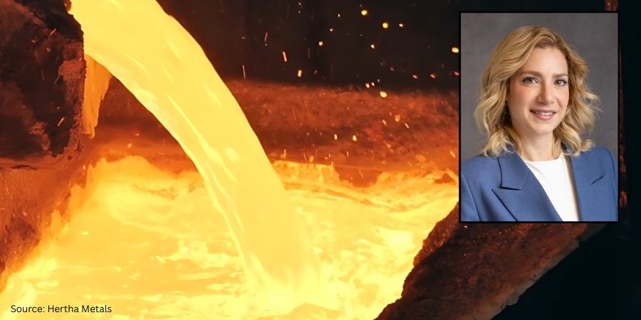
Hertha Metals has founded a technology with the potential to transform domestic steelmaking. The company’s proprietary technology is powered by natural gas, hydrogen, and electricity, enabling steel production from any grade of iron ore or waste oxide, in any format, including fines and lumps. Hertha’s process has been demonstrated at a continuous 1 tonne-per-day scale at their Conroe, TX facility, with plans to scale up to 9,000-tonnes, before launching a 500,000-tonne per year micro-mill.
This semi-continuous, single-step process delivers tunable iron and steelmaking. With Flex-HERS™, the proprietary technology, Hertha Metals can tap into domestic iron ore resources and produce low-emission steel using abundant natural gas. As clean hydrogen becomes more available and affordable, they plan to switch fuels — without changing the furnace, to remove the loss of stranded assets, and future-proof a path for steel production.
Hertha Metals steel production Source: Hertha Metals
The new technology:
Enables iron and steel production from low-grade ore, fines and waste oxides
Single-step production using abundant natural gas or clean hydrogen
Scalable technology to serve multiple markets
High-performance steel alloys under development
Laureen Meroueh CEO & Founder Hertha Metals Source:Linkedin
“After three short years of heads-down building, Hertha Metals is ready to show the world what we have achieved. After more than 300 years of coal-based primary steelmaking, Hertha Metals is introducing a process that is more energy efficient, more cost competitive, and more flexible with feedstock quality.
“The team at Hertha has been hard at work, developing and scaling our single-step ore-to-steelmaking technology. We have demonstrated our technology with various ore qualities and format (including fines) at a scale of 1 tonne per day of continuous clean steel production. This is the largest novel steelmaking pilot plant demonstration in the US and I am so proud of the speed at which we got here,” said CEO and founder, Laureen Meroueh.
Heat Treat Today original press release, last updated on 09/05/2025 at 5:15am.
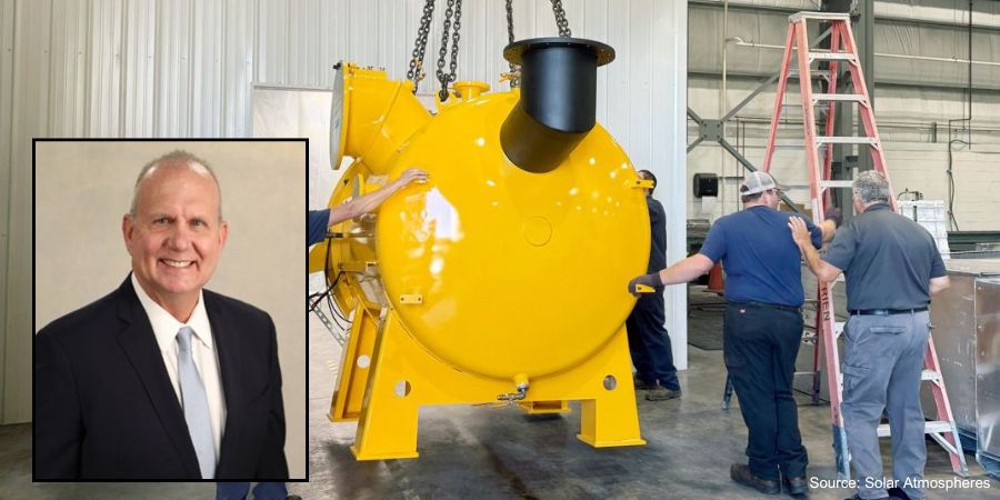
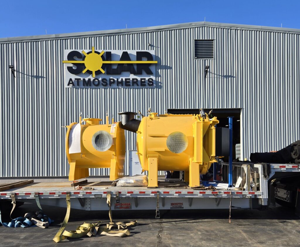
Solar Atmospheres of Western PA is expanding with the addition of a brand-new all-metal hot zone vacuum furnace. The furnace is engineered specifically for the high-vacuum processing of critical medical components.
Solar Atmospheres’ new vacuum furnace Source: Solar AtmospheresSolar Atmospheres’ new vacuum furnace Source: Solar AtmospheresRobert Hill, FASM President Solar Atmospheres of Western PA
“This new furnace is equipped with an all-molybdenum hot zone and a finely polished stainless steel cold wall. Critical vacuum pumping will be conducted on the vacuum chamber only with the integration of two (2) isolation valves. This design has proven to produce bright clean work on the critical medical device materials that we are processing. We now have identical furnaces in our clean room working 24/7,” commented Bob Hill, president of Solar Atmospheres of Western PA.
The furnace is 24” x 24” x 36” deep with an all-metal hot zone.
Solar Atmospheres supported this expansion by doubling the size of their existing medical clean room.
Heat Treat Today original press release, last updated on 09/04/2025 at 5:09am.
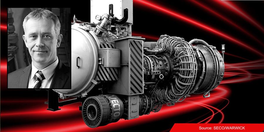
A vacuum furnace was commissioned for the global energy industry. The furnace is equipped with a large working space (900 x 900 x 1200 mm) and a rapid cooling system at pressures up to 6 bar for the production of gas turbine components.
Maciej Korecki Vice President of Vacuum Segment SECO/WARWICK Kamil Siedlecki Sales Manager SECO/WARWICK Source: LinkedIn
“This Partner is responsible for generating about 30% of the world’s electricity today, and their activities play a key role in the energy transition,” said Maciej Korecki, vice president of the Vacuum Segment of the SECO/WARWICK Group, which will provide the furnace.
The furnace is the ninth device delivered to this partner. It provides a high level of vacuum, convective heating up to 850°C, improved efficiency in lower temperature ranges, the capability of using three process gases (argon, nitrogen, hydrogen), precise partial pressure control to minimize alloy losses and ensure process purity, and consistent temperature distribution.
“This furnace is a response to the growing production needs of the client and the requirements related to the processing of a new type of gas turbine component. Our solution will increase process efficiency while maintaining the highest quality and process purity,” says Kamil Siedlecki, sales manager of SECO/WARWICK.
It is predicted that the value of the global gas turbine market for power generation will grow at an average growth rate (CAGR) of 5.7% from 2025–2034. This is driven by the energy transition and demand for efficient, environmentally friendly energy solutions.
Press release is available in its original form here.
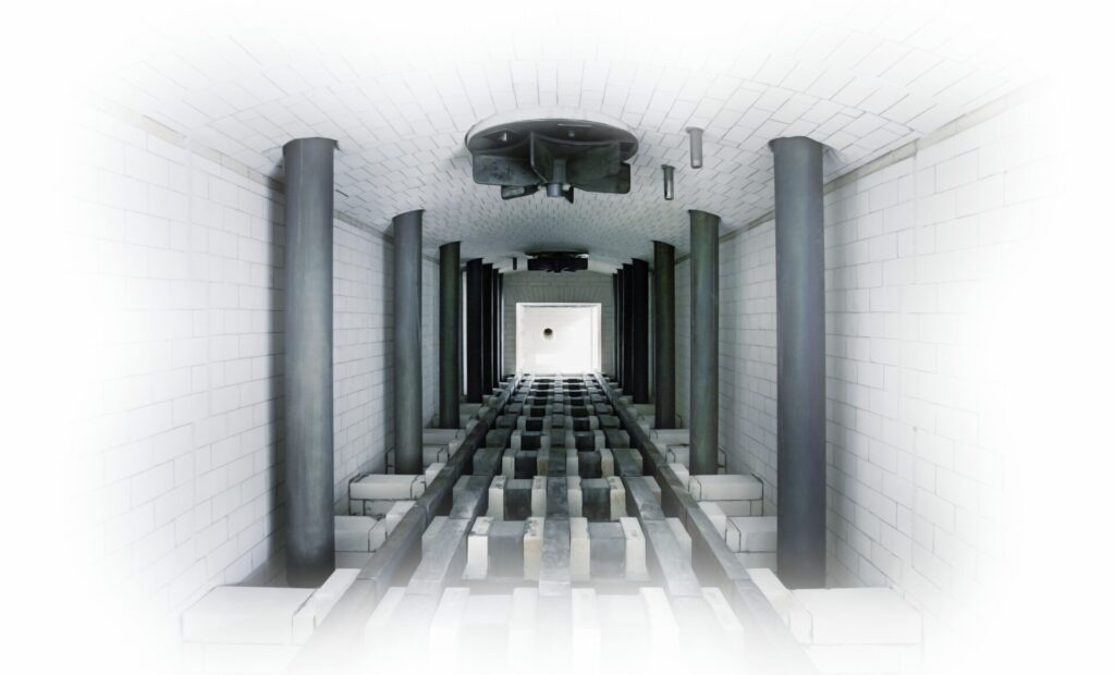
This Technical Tuesday installment is part of the Maintenance Message column series. In today’s edition Nate Sroka, quality assurance engineer for Ipsen, provides a complete maintenance guide to rebricking and relining atmospheric furnaces.Keep this one bookmarked for a quick reference to components, the rebricking process, expectations, and project timeline questions!
This informative piece was first released in Heat TreatToday’sAugust 2025 Automotive Heat Treating print edition.
Introduction
The interior brick walls of an atmosphere furnace endure extreme temperatures — sometimes reaching 2200°F — every hour of every day. Over time, the bricks become brittle, crack, and experience thermal expansion, which can open seams in the mortar.
After years of continuous operation, users may notice exterior walls becoming hot enough to melt insulated cables or components attached to the furnace. When bricks start falling out of place or insulation begins to sag, it’s time to shut down the furnace, assess damage, and plan for repairs. Typically, furnaces operating for five to ten years since installation or their last major overhaul require rebricking or relining.
Understanding the Components: Bricks and Boards
Knowing the key components used in the rebricking and relining process prepares you for discussions about repairs.
Insulated Fire Bricks (IFB) come in various temperature ratings. A 2300°F brick is less efficient and durable under extreme heat than a 2600°F brick but is often more cost-effective. High-rated bricks typically line the interior, while lower-rated bricks provide an additional insulation layer.
Insulating boards made from calcium silicate form the thermal barrier between the heating chamber and external components. They can withstand temperatures from 1000°F to 1800°F and are commonly used in lower-temperature furnaces.
Mineral wool is a fibrous insulating material used to fill gaps around furnace entry points and seams. Made from volcanic rock, ceramic, or slag, it allows for expansion and contraction due to temperature changes.
One key thing to know about atmosphere furnaces is that they are almost always “on.” In a vacuum furnace, recipes use electric elements that shut off after every cycle, and quenching often happens within the same chamber. However, in an atmosphere furnace, turning off the burners and then restarting the furnace from room temperature the next day is much less energy efficient than running the burners and holding a consistent temperature, even when the furnace is empty. Parts from an atmosphere furnace are typically quenched in an oil or salt bath, separate from the heating chamber.
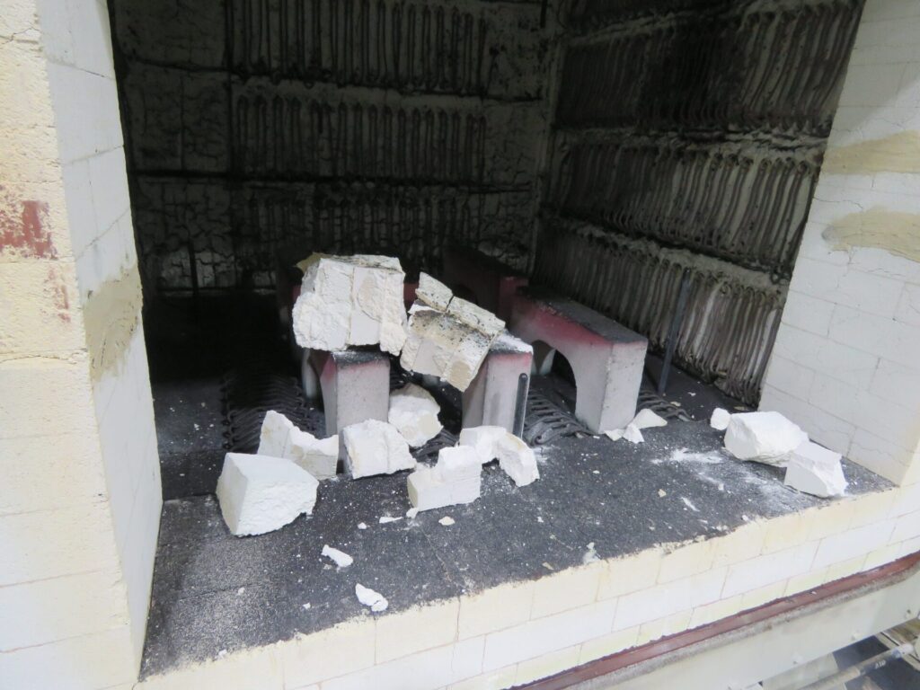
Figure 1. Debris from a damaged atmosphere furnace that collapsed on a hearth Source: Ipsen
Starting the Rebricking Process: What You Need to Know
Prepare for a Quote
First, review the pre-quote checklist to make sure you have the right information to get an accurate quote.
Pre-Quote Checklist: Important information to have on hand when getting a quote for rebricking or relining your atmosphere furnace
Furnace model number and serial number
Heating chamber dimensions (w/d/h)
Archway dimensions from base to top
Door dimensions and condition
Drawings or engineering plans outlining any aftermarket modifications
Typical operating temperatures
Any additional materials installed to prevent heat penetration
Photos from as many angles of the furnace as possible
A list of any consumable or heavy-wear components that also need to be replaced
Build a Timeline
Start collecting quotes at least a year in advance and place a purchase order no less than six months before the planned shutdown.
Consider Scheduling Factors
Many furnace operators are looking to have work like this completed during a summer or winter holiday shutdown period. Advanced planning improves scheduling flexibility.
Site Preparations
Before the service team arrives, ensure the workspace is ready:
Clear space for staging new materials and removing old bricks.
Provide access to a forklift, a durable waste collection container, a dumpster, and other required tools and resources.
Confirm power connections near the site for welding and other power tools.
Review lockout/tagout procedures with maintenance and operations teams.
Determine the required furnace cool-down time before disassembly and plan furnace shutdown accordingly.
Identify and disconnect any electrical, process gas, or water-cooling lines as outlined prior to service.
Rebricking Day: What You Should Expect
During disassembly, consider performing additional maintenance, such as:
Inspecting and rotating or replacing burner tubes
Inspecting and replacing pusher chains and skid hearth section
Checking doors, door hoods, and fan bungs
Conducting leak tests and changing the quench oil
Coordinate these tasks with the service team to avoid disruptions. The rebricking process spans several days, allowing time for concurrent inspections and repairs.
Final Inspection and Testing
Upon project completion:
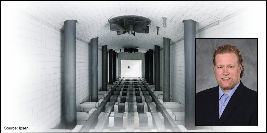
Figure 2. A newly installed furnace, bricks properly installed, before furnace ignition Source: Ipsen
Inspect the furnace with the installation team to ensure all work aligns with project specifications.
Document any changes as a reference for future maintenance.
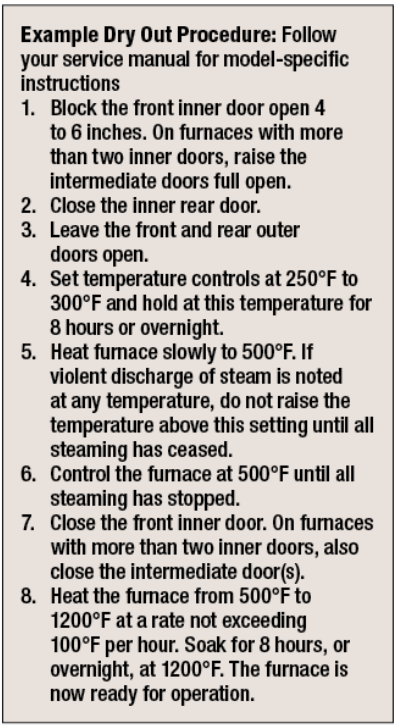
Perform a “dry out” procedure and clean the quench tank before refilling the tank. See “Example Dry Out Procedure” break-out box.
Run the furnace without parts to test for temperature uniformity.
Carburizing furnaces may need extra burn-in time to “season” the bricks:
Fresh bricks absorb free carbon until fully saturated.
When bricks are properly saturated, furnace atmospheres stabilize.
Time of burn-in is dependent on the percentage of carbon-level the system needs to achieve.
Identify potential hot or cold spots that may require further insulation adjustments.
Post-Installation Best Practices
A rebrick or reline of a furnace is a significant investment. To get the most from your furnace, make the time to take a proactive approach:
Establish a daily maintenance inspection for the first week, followed by weekly checks for the first month.
Resume regular maintenance schedules if no issues arise.
Schedule independent inspections with a field service engineer at three, five, seven, and nine years to proactively assess furnace condition and secure preferred maintenance dates.
By following these steps, atmosphere furnace operators can maximize uptime, streamline service quoting, optimize downtime usage, and ensure efficient future rebuilds.
This article was originally published on ipsenusa.com.
About The Author:
Nate Sroka Quality Assurance Engineer Ipsen
Nate Sroka has been with Ipsen since March 2014. He holds a bachelor’s degree in mechanical engineering and a master’s degree in engineering and industrial management from Northern Illinois University. Nate oversees the Quality/Documentation/Warranty (QDW) department, ensuring that Ipsen maintains ISO 9001 and ISO/IEC 17025 standards. He is also responsible for documentation related to installation and operations manuals, regulatory certificates, and managing warranty programs.
For more information: Contact Nate Sroka at nate.sroka@ipsenusa.com.
Heat Treat Today offices will be closed today in honor of Labor Day and will reopen on Tuesday, September 2. We hope you enjoy the long weekend with friends and family!
IperionX Limited will receive $12.5 million from the U.S. Department of Defense (DoD) to accelerate the scale-up of a resilient, low-cost, and fully-integrated U.S. mineral-to-metal titanium supply chain. The project will include scaling up to over 1,000 metric tons per year at the Virgnia Titanium Manufacturing Campus.
The $12.5 million will be applied to purchase orders for long-lead, major capital equipment required for the scale-up. Major incremental capacity categories include titanium deoxygenation, sintering and powder metallurgy consolidation systems; near-net-shape component manufacturing and ancillary infrastructure upgrades.
Anastasios (Taso) Arima CEO IperionX Source: IperionX
“This new U.S. Government obligation allows IperionX to move immediately to secure long-lead capital equipment and lock in manufacturing slots with key suppliers. It accelerates our imminent Virginia expansion beyond 1,000 tpa of high-performance titanium manufactured products, and advances a fully integrated, low-cost and traceable American titanium supply chain for defense and commercial customers. This commitment from the DoD is a strong endorsement of our technology, our team, and our mission to reshore a resilient titanium production supply chain in the United States,” said Anastasios (Taso) Arima, IperionXCEO.
In response to the strategic need for increased production capacity of domestic primary titanium metal and manufactured titanium metal components, the project scope under the Industrial Base Analysis and Sustainment (IBAS) program has been revised to prioritize accelerated expansion of IperionX’s titanium metal and manufacturing production capacity at IperionX’s Virginia Titanium Manufacturing Campus.
This project is part of a previously announced $47.1 million award to strengthen the U.S. Defense Industrial Base by accelerating the scale-up of a resilient, low-cost, and fully-integrated U.S. mineral-to-metal titanium supply chain.
Press release is available in its original form here.
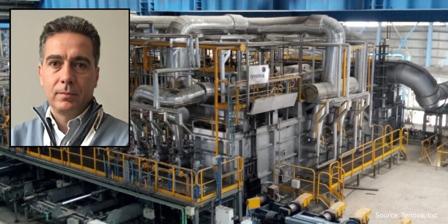
Vinton Steel, headquartered in Vinton, Texas, has commissioned a new walking hearth reheating furnace. The furnace will be engineered for high-carbon steel billets used to manufacture large-diameter grinding media, a high demand product for the mining sector.
This addition is intended to operate alongside a new initiative to increase Vinton Steel’s rebar production capacity up to 400,000 tons per year. The initiative is called Green CityMill™ Flex, which represents an efficient and sustainable long products production platform.
Francesco Memoli
President & CEO
Tenova Inc.
“This project is part of the strategic expansion of Kyoei Steel in the vital North American market and a clear demonstration of our long-term commitment to the State of Texas,” said Masahiro Kitada, board director & executive managing officer for Kyoei Steel Group and chairman of Vinton Steel. “With this additional project, we contribute even more to the continued growth of the El Paso region.”
Francesco Memoli, president and CEO of Tenova Inc., added: “We are honored that Vinton Steel continues to place its trust in Tenova’s technologies. This new reheating furnace will be the most advanced of its kind, equipped with sophisticated control systems and our proprietary low-NOx burners.”
The reheating furnace is scheduled for commissioning in parallel with the Green CityMill™ Flex startup in the first half of 2027.
Press release is available in its original form here.
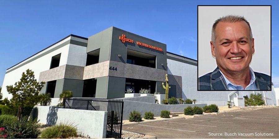
Busch Vacuum Solutions, part of the Busch Group, a global company in vacuum and overpressure technology, has announced the development of its newest U.S. facility. As a key regional hub, the facility will specialize in the repair, service, and overhaul of vacuum pumps, vacuum systems, and overpressure equipment including turbo molecular pumps, leak detectors, valves, and accessories. The almost 60,000-square-foot facility will be located in Tempe, Arizona.
Turgay Ozan President & CEO Busch Group USA
The state-of-the-art facility is scheduled to open in October 2025. This expanded capability brings greater flexibility, technical expertise, and responsiveness to customers across the semiconductor, industrial, medical, and environmental sectors. The Tempe Service Center will provide faster turnaround times, expert support, and more efficient service delivery tailored to the unique operational needs of those across the U.S.
“This investment represents more than just added square footage. It’s about proximity, partnership, and performance. With the launch of our Tempe location, we’re better positioned to deliver unmatched value…on advanced vacuum technologies in high-performance environments,” said Turgay Ozan, president & CEO of Busch GroupUSA.
Corey Woods Mayor Tempe, Arizona
The mayor of Tempe, Corey Woods, commented, “We’re excited to welcome Busch Vacuum Solutions…Their decision to invest here speaks to the strength of Arizona’s semiconductor ecosystem, diversity of thriving industries located here, and the spirit of innovation that defines our community. The new Tempe Service Center will create skilled employment opportunities, strengthen business partnerships, and keep Tempe at the forefront of high-tech growth and excellence.”
In addition to semiconductor and industrial markets, Busch’s vacuum technology supports automotive, food and beverage, packaging, metallurgy, pharmaceuticals, plastics, and large-scale distribution. These capabilities enable more localized production and increase operational resilience across essential supply chains.
Press release is available in its original form here.
The Heat Treat Doctor® has returned to offer sage advice to Heat Treat Today readers and to answer your questions about heat treating, brazing, sintering, and other types of thermal treatments as well as questions on metallurgy, equipment, and process-related issues.
This informative piece was first released in Heat Treat Today’sAugust 2025 Automotive Heat Treating print edition.
Quench cracking during heat treatment can turn expensive components into scrap metal in seconds. In today’s Technical Tuesday article, Dan Herring (The Heat Treat Doctor®) explores more about the underlying mechanisms and proper preventative measures to save you time, money, and ensure reliable part performance.
As a young heat treater, I learned first-hand about quench cracking while running various dies for our tool and die shop — and succeeded in cracking all of them! I have never forgotten the foreman’s (rather animated) critique of my heat treating abilities. Quench cracking can be a significant problem for heat treaters, its potential consequences ranging from costly rework to premature failure in the field. Let’s learn more.
We must not only understand the mechanisms involved but also take proactive steps to avoid it. This includes careful consideration of such items as:
Material (e.g., chemistry, hardenability, form, mill processing)
Component part design (e.g., sharp radii, thin and thick sections next to one another)
Manufacturing processing steps (e.g., the effect of stress relief after rough machining)
Part loading (e.g., part orientation in relation to the quench, fixturing, total load weight)
Equipment choice (i.e., limitations and capabilities)
Quench medium (e.g., type, agitation, flow characteristics, temperature, temperature rise)
Process parameters (e.g., ramp rates, atmospheres, vacuum levels)
The Heat Treatment Challenge
Quench cracking primarily occurs during the hardening process, typically when materials are rapidly cooled via quenching. Since the cooling process introduces internal stresses within the material, it can result in crack formation. These stresses are a result of the rapid transformation of the material’s microstructure, most notably when transforming to martensite, a very hard, brittle structure.
Figure 1. Quench crack in a 4140 axle shaft
Mechanisms Involved
Failure mechanisms related to quench cracking include the following seven factors.
Material Imperfections
As material is heated, thermally induced stresses can cause existing surface or subsurface defects, such as inclusions, laps, and seams. These defects act as stress risers to open and propagate into cracks. Once a defect reaches “critical flaw size” — the smallest flaw that can lead to failure under expected operational stress levels — crack propagation will begin and lead to part failure.
Rapid or uneven heating only exacerbates this issue, especially when a material undergoes phase transformations that introduce volumetric changes.
Stress Risers
Sharp corners, steep edges around holes, and even grooves in parts create stress concentration points where quench cracking is most likely to occur. These features also result in localized heating and cooling, causing differential stresses that can initiate cracks.
The sharp edges of a part, for instance, cool much faster than the rest of the material, leading to a high risk of cracking.
Proper design modifications, such as adding radii to sharp corners, can reduce the likelihood of stress concentrations.
Rapid Cooling and Phase Transformation
The transformation from austenite to martensite during quenching is a key contributor to internal stresses. The rate at which the material cools can greatly influence these stresses. If cooling is too rapid or if tempering is delayed, the material can become overly brittle, leading to quench cracking.
Improper Heating and Overheating
Overheating during the austenitizing process can lead to coarse-grained structures that are more prone to quench cracking. Coarse grains increase the depth of hardening but reduce the material’s resistance to cracking. It is critical to avoid temperature overshoot, high ramp rates, and excessively long dwell times when heating.
Inadequate Quenching Methods
The choice of quench medium (brine, water, oil, polymer, high pressure gas, etc.) can also contribute to quench cracking. Overly aggressive quenchants may create excessive thermal stresses.
Improper Fixturing
The way parts are positioned during quenching can create problems. If parts are bunched together in a basket, uneven cooling rates will occur, with parts on the edges cooling faster than those in the center. This can lead to differential stresses and increase the risk of cracking.
Delays Between Quenching and Tempering
Quenching produces high residual stresses in the material, and if parts are not tempered soon after quenching, these stresses can lead to cracking. For materials with high hardenability, such as 4340 steel, immediate tempering (usually within 15 minutes of quenching) is critical to prevent in-service failure.
Understanding Fracture Mechanics
Contact us with your Reader Feedback!
Understanding these mechanisms is critically important. A material’s fracture toughness, which is the ability to resist crack growth, is defined by the stress intensity factor (KIC). This value varies based on the material’s properties and the size and geometry of the crack. The important point to remember is that when the applied stress reaches a critical threshold, cracks begin to propagate (literally at the speed of sound), leading to catastrophic failure.
Digging a bit deeper, there are three primary modes of fracture:
Tensile (Mode I): Fracture caused by tensile stress at the crack tip.
Sliding (Mode II): Fracture caused by shear stress that causes the two sides of the crack to slide.
Tearing (Mode III): Fracture caused by shear forces in a direction perpendicular to the crack plane.
Preventive Measures
Several strategies can be employed to minimize the risk of quench cracking during heat treatment. They broadly fall into the following categories.
Material Selection
Choosing the right material for the job is essential. Many designers select materials with high hardenability, forgetting that they can be prone to cracking. Additionally, one should take special care with materials that have high carbon content or are heavily alloyed.
Design Considerations
Ensure that part designs minimize stress risers. Avoid sharp corners and incorporate radii where necessary. Proper design can reduce the likelihood of cracks forming at critical locations.
Improved Manufacturing Practices
Proper stock removal during machining and addressing surface imperfections before heat treatment can prevent the initiation of cracks. Machining should aim to eliminate any seams or inclusions that might act as nucleation sites for cracks. Stress relief after rough machining is almost always a good idea.
Control of Heat Treatment Parameters
Maintain tight control over the heating and quenching processes to ensure uniformity. Avoid overheating and try to ensure that the part enters the quench medium in the best possible orientation to reduce the likelihood of creating differential cooling rates.
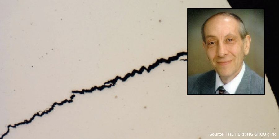
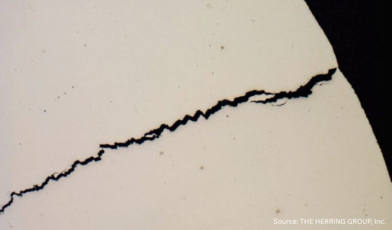
Figure 2. Quench crack due to a combination of rapid heating, overheating and improper
polymer quench medium concentration in a motor shaft (50x, as polished)
Quenching Media
Select the appropriate quenching medium based on the material, part geometry, and load. Less aggressive quenchants or minimizing time in the quench should be considered for materials with moderate to high hardenability.
Post-Quench Tempering
Temper parts as soon as practical after quenching to avoid concerns with internal stresses. High-hardness materials should be tempered immediately to prevent quench cracking.
Quench Cracking in Other Materials
Quench cracking is not exclusive to steel. Other materials, such as nickel and cobalt superalloys, can also experience cracking due to similar mechanisms. In these materials, the phenomena are often referred to as “fire cracking,” “strain-age cracking,” or “stress cracking.” As with steel, cracks in these materials are often linked to high residual tensile stresses on the surface and the presence of stress raisers. Strategies, such as shot peening, redesigning part geometries, and improving surface finishes, can help mitigate cracking in superalloys.
Summing Up
Quench cracking represents a significant challenge in heat treatment, but by understanding its underlying mechanisms, heat treaters and engineers can take steps to mitigate the risk. Material selection, part design, proper heat treatment procedures, and timely tempering are all critical factors in preventing quench cracking and ensuring the integrity of components. A proactive approach to addressing flaws and stress concentrators combined with careful attention to detail in every stage of the manufacturing and heat treatment process can greatly reduce the likelihood of failure and contribute to the long-term success of heat treated products.
References
Herring, Daniel H. 2012. “Quench Cracking.” Industrial Heating, April.
Herring, Daniel H. 2015. Atmosphere Heat Treatment, Volume 2. BNP Media.
Johnson, D. D. 2005. “Thermal and Mechanical Behavior of Materials.” University of Illinois.
Klarstrom, Dwaine L. 1996. “Heat Treat Cracking of Superalloys.” Advanced Materials and Processes, April.
Krauss, George. 2005. Steels: Processing, Structure and Performance. ASM International.
About the Author
Dan Herring “The Heat Treat Doctor” The HERRING GROUP, Inc.
Dan Herring has been in the industry for over 50 years and has gained vast experience in fields that include materials science, engineering, metallurgy, new product research, and many other areas. He is the author of six books and over 700 technical articles.