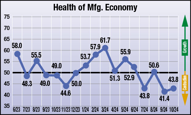
The four heat treat industry-specific economic indicators have been gathered by Heat Treat Today each month since June 2023. Last month, suppliers were split between anticipated growth and no change or contraction. This month, the four economic indicators are all reflecting anticipated contraction.
The numbers, which were compiled in the first week of October, show that responding parties expect the economy to experience contraction in all the four indices. In three of the four, the numbers change by more than 5 points from growth or no change to contraction. For anticipated health of the manufacturing economy, suppliers anticipate contraction, although in an improved range.
The results from this month’s survey (October) are as follows; numbers above 50 indicate growth, numbers below 50 indicate contraction, and the number 50 indicates no change:
Anticipated change in Number of Inquiries from September to October: 44.6
Anticipated change in Value of Bookings from September to October: 44.8
Anticipated change in Size of Backlog from September to October: 42.9
Anticipated change in Health of the Manufacturing Economy from September to October: 43.8
Data for October 2024
The four index numbers are reported monthly by Heat Treat Today and made available on the website.
Heat TreatToday’sEconomic Indicatorsmeasure and report on four heat treat industry indices. Each month, approximately 800 individuals who classify themselves as suppliers to the North American heat treat industry receive the survey. Above are the results. Data started being collected in June 2023. If you would like to participate in the monthly survey, please click here to subscribe.
The Heat Treat Doctor® has returned to offer sage advice to Heat Treat Today readers and to answer your questions about heat treating, brazing, sintering, and other types of thermal treatments as well as questions on metallurgy, equipment, and process-related issues.
The Heat Treat Doctor® ha vuelto para ofrecer sabios consejos a los lectores de Heat Treat Today y para responder a suspreguntas sobre el tratamiento térmico, brazing, sinterizado y otros tipos de procesamiento térmico, así como preguntassobre metalurgia, equipos y problemasrelacionados con los procesos.
This article was originally published inHeat Treat Today‘sSeptember 2024 People of Heat Treat print edition.
Quenching is a critical step in the heat treating process. And while there are often several choices available to the heat treater, a delicate balance exists between what is available to us and how we can optimize its performance characteristics to meet our client’s requirements/specifications. Material, part design (geometry), pre-and post-manufacturing requirements, loading, allowable dimensional change (i.e., distortion), and the process itself must be taken into careful consideration. Let’s learn more.
Quenchants — A Brief Overview
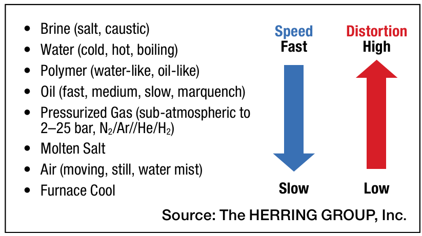
Today’s quenchants offer a broad and, in some instances, overlapping range of capabilities. But at a fundamental level, the role of a quenchant is to extract heat from the part surface to meet a specified critical cooling rate and achieve the desired microstructure in the component part necessary to achieve the required mechanical and physical properties. In hardening of steels, for example, one must miss the “nose” of the time-temperature transformation (TTT) curve if the desired end-result is a martensitic (or bainitic) microstructure. By contrast, the cooling rate for a normalizing process requires cooling in “still air” — a term that is often misunderstood and which we will cover in a future discussion.
Figure 1. Common types of quenchants and their effect on distortion (See Reference 1)
However, a quenchant (Figure 1) is more than just its cooling rate. Quenchants should be stable over their service life, especially with respect to degradation (e.g., oxidation), be safe, be easy to service and maintain, have a high vaporization point, ideally not interact with the part surface, be used within their optimum performance range, have long life, be easily removed by cleaning after quenching, and be cost effective.
As a very broad-based characterization, quenchants can be divided into the following general categories:
Mixed media quenchants (e.g., mist or fog quenching, fluidized beds)
Figure 2. Ishikawa (aka fishbone) diagram of quenching variables (See Reference 1)
Selection of the Optimal Quench Medium
Contact us with your Reader Feedback!
Various factors must be taken into consideration when selecting the best quench medium. The following are some of the important considerations when selecting the proper quench medium (Figure 2):
Material — chemistry, hardenability, form (e.g., bar, plate, forging, casting), type (e.g., wrought, powder metal), and cleanliness to name a few
Part geometry/design — shape, size, weight, complexity
Mill or preheat treatment condition — annealed, normalized, pre-hardened, stress-relieved
Stress state — the cumulative effect of both mill operations and customer manufacturing operations prior to heat treatment
Process parameters — temperature, time, preheating
Equipment selection — is it optimal or simply adequate for the job?
Quench medium(s) available — their limitations as well as their advantages
It is important to talk briefly here about two aspects of the quench medium selection process. First, note the difference between hardness and hardenability (which we will discuss in more detail in the future). Heat treaters tend to focus on hardness (since we can easily measure it in our shops), but hardenability is a critical consideration in quench medium selection. Hardenability is a material property independent of cooling rate and dependent on chemical composition and grain size. When evaluated by hardness testing, hardenability is defined as the capacity of the material under a given set of heat treatment conditions to harden “in-depth.” In other words, hardenability is concerned with the “depth of hardening,” or the hardness profile obtained, not the ability to achieve a particular hardness value. When evaluated by microstructural techniques, hardenability is defined (for steels) as the capacity of the steel to transform partially or completely from austenite to a defined percentage of martensite.
Table 1. Average and instantaneous values of the heat transfer coefficient (See Reference 3)
Second, one must be aware of both the average and instantaneous value of the heat transfer coefficient alpha of the quench medium. Although the maximum quenching “power” may be described by the instantaneous heat transfer coefficient, the average heat transfer coefficient (Table 1) provides a better relative comparison of the various quenching media since it represents the value of the heat transfer coefficient over the entire range of cooling (from the start to the end of quenching). It is important to remember that the ability to manage (not control) distortion is a delicate balancing act between uniform heat extraction and proper transformation.
A Common Example — Quench Oil Selection
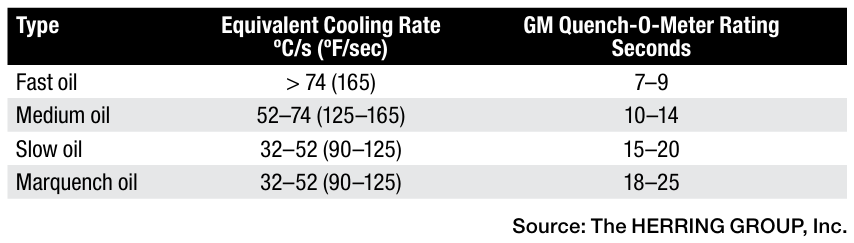
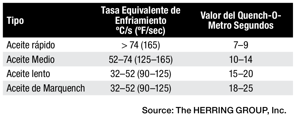
Important factors to consider when selecting a quench oil, which hold true in a slightly modified form for most liquid quenchants, are: the type of quenchant (i.e., quench characteristics, cooling curve data — new and over time); quench speed (see Table 2); usage temperature; effective quench tank volume (i.e., the one gallon per pound of steel [8.4 L/kg] rule); and the client’s requirements.
Table 2. Classification of quench oils (See Reference 1)
Quench tank design factors also play an important role and involve the following:
Volume of oil in the quench tank
Number of agitators or pumps
Location of agitators
Type of agitators (fixed or variable speed)
Internal tank baffle arrangement (draft tubes, directional flow vanes, etc.)
Quench elevator design (i.e., flow restrictions)
Quenchant flow direction (up or down through the load)
Propeller size (diameter, clearance in draft tube)
Maximum (design) temperature rise of the oil after quenching
Finally, consideration must be given to factors such as: part mass; part geometry (e.g., thin and thick sections, sharp corners and holes, gear tooth profile/modulus, thread profile, etc.); part spacing in the load; effective flow velocity through the quench area (empty and with a load); stress state from prior (manufacturing) operations; post heat treat operations to be performed (if any); loading including the grids, baskets, and fixture (material and design); and the material (chemistry and hardenability).
Final Thoughts
Quenching, considered by many to be a complex and multi-faceted subject, is one heat treaters must constantly monitor and control. In future installments we will be discussing many of the individual aspects of quenching. What is important here is to recognize that done correctly, quenching (in whatever form) will optimize a given heat treatment and help produce the highest quality parts demanded by the industries we serve.
References
Daniel Herring, Atmosphere Heat Treatment, Volume II: Atmospheres | Quenching | Testing (BNP Media Group, 2015).
Božidar Liščić et al., Quenching Theory and Technology, Second Edition (CRC Press, Taylor Francis Group, 2010).
Daniel Herring, “A Review of Gas Quenching from the Perspective of the Heat Transfer Coefficient,” Industrial Heating, February 2006.
About the Author
Dan Herring “The Heat Treat Doctor” The HERRING GROUP, Inc.
Dan Herring has been in the industry for over 50 years and has gained vast experience in fields that include materials science, engineering, metallurgy, new product research, and many other areas. He is the author of six books and over 700 technical articles.
The Heat Treat Doctor® ha vuelto para ofrecer sabios consejos a los lectores de Heat Treat Today y para responder a suspreguntas sobre el tratamiento térmico, brazing, sinterizado y otros tipos de procesamiento térmico, así como preguntassobre metalurgia, equipos y problemas relacionados con los procesos.
The Heat Treat Doctor® has returned to offer sage advice to Heat Treat Today readers and to answer your questions about heat treating, brazing, sintering, and other types of thermal treatments as well as questions on metallurgy, equipment, and process-related issues.
This article was originally published inHeat Treat Today‘sSeptember 2024 People of Heat Treat print edition.
El temple es un paso fundamental en el proceso de tratamiento térmico. Y si bien el especialista en tratamiento térmico suele tener varias opciones disponibles, existe un delicado equilibrio entre lo que está disponible para nosotros y cómo podemos optimizar sus características de rendimiento para cumplir con los requisitos/especificaciones de nuestros clientes. Se deben tener en cuenta cuidadosamente el material, el diseño de la pieza (geometría), los requisitos previos y posteriores de manufactura, la carga, el cambio dimensional permitido (es decir, la distorsión) y el proceso como tal. Conozcamos más.
Medios de temple: una breve Descripción
Los medios de temple actuales ofrecen una amplia gama de capacidades que, en algunos casos, se traslapan. Sin embargo, en un nivel fundamental, la función de un medio de temple es extraer calor de la superficie de la pieza para cumplir con una velocidad crítica de enfriamiento especificada y con ello lograr la microestructura necesaria para lograr las propiedades mecánicas y físicas requeridas. En el temple de aceros, por ejemplo, se debe evitar pasar por la “nariz” de la curva de transformación-tiempo-temperatura (TTT) si el resultado final deseado es una microestructura martensítica (o bainítica). Por el contrario, la velocidad de enfriamiento para un proceso de normalización requiere enfriamiento “al aire”, un término que a menudo se malinterpreta y que abordaremos en una discusión futura.
Figura 1. Medios de Temple comunes y su efecto en la distorsión (1)
Sin embargo, un medio de temple (Figura 1) es más que solo su velocidad de enfriamiento. Los medios de temple deben ser estables durante su vida útil, especialmente con respecto a la degradación (por ejemplo, oxidación), ser seguros, ser fáciles de arreglar y mantener, tener un alto punto de vaporización, idealmente no interactuar con la superficie de la pieza, usarse dentro de su rango de rendimiento óptimo, tener una larga vida útil, eliminarse fácilmente mediante limpieza después del temple y ser rentables.
A manera de una caracterización muy amplia, los medios de temple se pueden dividir en las siguientes categorías generales:
Medios de temple líquidos (p. ej., a base de agua, aceites, polímeros, sales fundidas y metales fundidos)
Medios de temple gaseosos (p. ej., aire, nitrógeno, argón, hidrógeno, vapor, dióxido de carbono, dióxido de azufre, gases reductores, atmósferas protectoras sintéticas o generadas, gases a alta presión)
Medios de temple sólidos (p. ej., dados de prensa enfriados, placas y polvos)
Medios de medios mixtos (p. ej., temple por aspersión, lechos fluidizados)
Figura 2. Diagrama de Ishikawa (también conocido como de pescado) de las variables de temples (1)
Selección del medio de temple óptimo
Contact us with your Reader Feedback!
Se deben tener en cuenta varios factores al seleccionar el mejor medio de temple. A continuación, se enumeran algunos de los aspectos importantes a tener en cuenta al seleccionar el medio adecuado (Figura 2):
Material: composición química, templabilidad, forma (p. ej., barra, placa, forja, fundición), tipo (p. ej., forjado, sinterizado) y limpieza, por nombrar algunos
Geometría/diseño de la pieza: forma, tamaño, peso, complejidad
Estado de laminación o tratamiento térmico previo: recocido, normalizado, preendurecido, relevado de esfuerzos
Estado de tensión: el efecto acumulativo de las operaciones de laminación y las operaciones de fabricación del cliente antes del tratamiento térmico
Carga: canastillas (aleación, compuesto C/C, placas de grafito, etc.)
Parámetros del proceso: temperatura, tiempo, precalentamiento
Selección del equipo: ¿es óptimo o simplemente adecuado para el trabajo?
Medio(s) de temple disponibles: sus limitaciones y ventajas
Es importante hablar brevemente aquí sobre dos aspectos del proceso de selección del medio de temple. Primero, observar la diferencia entre dureza y templabilidad (que analizaremos con más detalle en el futuro). Los tratadores térmicos tienden a centrarse en la dureza (ya que podemos medirla fácilmente en nuestro taller), pero la templabilidad es una consideración crítica en la selección del medio de temple. La templabilidad es una propiedad del material independiente de la velocidad de enfriamiento y dependiente de la composición química y el tamaño del grano. Cuando se evalúa mediante pruebas de dureza, la templabilidad se define como la capacidad del material bajo un conjunto dado de condiciones de tratamiento térmico para endurecerse “en profundidad”. En otras palabras, la templabilidad se relaciona con la “profundidad de endurecimiento”, o el perfil de dureza obtenido, no con la capacidad de alcanzar un valor de dureza particular. Cuando se evalúa mediante técnicas microestructurales, la templabilidad se define (para aceros) como la capacidad del acero para transformarse parcial o completamente de austenita a un porcentaje definido de martensita.
Tabla 1. Valores medios e instantáneos del coeficiente de transferencia de calor (3)
En segundo lugar, se debe tener en cuenta tanto el valor medio como el instantáneo del coeficiente de transferencia de calor alfa (α) del medio de temple. Aunque la “potencia” máxima de temple se puede describir mediante el coeficiente de transferencia de calor instantáneo, el coeficiente de transferencia de calor promedio (Tabla 1) proporciona una mejor comparación relativa de los diversos medios de temple, ya que representa el valor del coeficiente de transferencia de calor en todo el rango de enfriamiento (desde el inicio hasta el final del temple). Es importante recordar que la capacidad de gestionar (no controlar) la distorsión es un delicado acto de equilibrio entre la extracción uniforme del calor y la transformación adecuada.
Tabla 2. Clasificación de los aceites de temple (1)
Un ejemplo común: selección de aceite de temple
Los factores importantes a tener en cuenta al seleccionar un aceite de temple, que son válidos en una forma ligeramente modificada para la mayoría de los medios líquidos, son: el tipo de medio (es decir, características del temple, datos de la curva de enfriamiento, nuevo y a lo largo del tiempo); velocidad de temple (consulte a Tabla 2); temperatura de uso; volumen efectivo del tanque de enfriamiento [es decir, la regla de un galón por libra de acero (8,4 L/kg)]; y los requisitos del cliente.
Los factores de diseño del tanque de temple también juegan un papel importante e involucran lo siguiente:
Volumen de aceite en el tanque de temple
Número de recirculadores o bombas
Ubicación de los recirculadores
Tipo de recirculadores (velocidad fija ovariable)
Disposición de los deflectores internos del tanque (tubos de aspiración, álabes de flujo direccional, etc.)
Diseño del elevador de temple (es decir, restricciones de flujo)
Dirección del flujo del temple (hacia arriba o hacia abajo a través de la carga)
Tamaño de la propela (diámetro, espacio libre en el tubo de aspiración)
Máximo incremento dela temperatura (diseño) delaceite después del temple
Altura del aceite sobre la carga
Intercambiador de calor: tipo, tamaño, tasa de extracción de calor (BTU instantáneos/minuto)
Tiempo de recuperación del aceite hasta el set point
Por último, se deben tener en cuenta factores como: la masa de la pieza; la geometría de la pieza (por ejemplo, secciones delgadas y gruesas, esquinas y barrenos afilados, perfil de los dientes del engrane, perfil de la rosca, etc.); espaciamiento de la pieza en la carga; velocidad de flujo efectiva a través del área de temple (vacía y con carga); estado de tensión de operaciones anteriores (de manufactura); operaciones de tratamiento térmico posteriores a realizar (si las hay); carga, incluidas las charolas, las canastillas y el herramental (material y diseño); y el material (composición química y templabilidad).
Reflexiones finales
El temple, considerado por muchos como un tema complejo y multifacético, es un asunto que los especialistas en tratamiento térmico deben supervisar y controlar constantemente. En futuras entregas, analizaremos muchos de los aspectos individuales del temple. Lo importante aquí es reconocer que, si se realiza correctamente, el temple (en cualquier forma) optimizará un tratamiento térmico determinado y ayudará a producir las piezas de la más alta calidad que exigen las industrias a las que prestamos nuestros servicios.
Referencias
Daniel Herring, Atmosphere Heat Treatment, Volume II: Atmospheres | Quenching | Testing (BNP Media Group, 2015).
Bozidar Liscic et al., Quenching Theory and Technology, Second Edition (CRC Press, Taylor Francis Group, 2010).
Daniel Herring, “A Review of Gas Quenching from the Perspective of the Heat Transfer Coefficient,” Industrial Heating, February 2006.
Sobre el autor
Dan Herring “The Heat Treat Doctor” The HERRING GROUP, Inc.
Dan Herring ha trabajado en la industria durante más de 50 años y ha adquirido una vasta experiencia en campos que incluyen ciencia de materiales, ingeniería, metalurgia, investigación de nuevos productos y muchas otras áreas. Dan es autor de seis libros y más de 700 artículos técnicos.
Para más información: Comuníquese con Dan en dherring@heat-treat-doctor.com.
For more information about Dan’s books: see his page at the Heat Treat Store.
Find Heat Treating Products And Services When You Search On Heat Treat Buyers Guide.Com
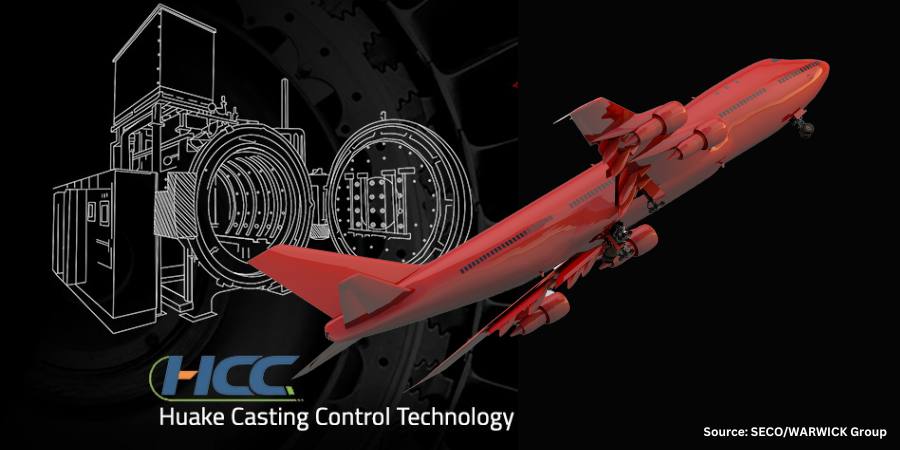
A manufacturer of components for the aviation and energy sectors is expanding its production capabilities with the acquisition of a horizontal vacuum heat treatment furnace. Huake Casting Control (Shanghai) Technology Co., Ltd., will use the equipment to manufacture precision gas turbine components and aircraft parts.
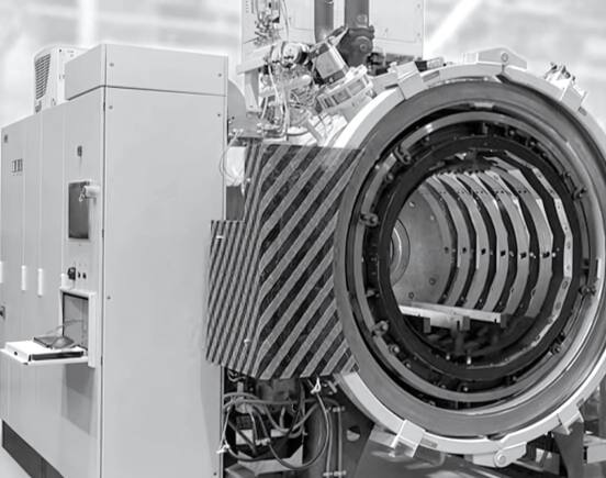
A Vector® horizontal vacuum heat treatment furnace Source: SECO/WARWICK Group
The solution, a member of the Vector® family of furnaces provided by SECO/WARWICK Group, comes with a graphite heating chamber and a 15-bar absolute gas quenching system, can operate at temperatures up to 2550°F (1400°C), and has a maximum gross load weight of 1767 lb (800 kg).
“We were convinced to choose the Vector furnace because of its wide range of heat treatment processes and applications, fast cycles with high pressure gas quenching and low consumption of energy, process gases and other media. Another undoubted advantage is that Vector is environmentally friendly and has low process gas emissions,” said Li Naixu, chairman of Huake Casting Control (Shanghai) Technology Co., Ltd.
“Huake Casting Control Technology has become our customer as the result of the SECO/WARWICK Group’s increasing reputation in Asia. . . . We want to provide partners with solutions which will allow them to grow and achieve their intended goals related to production, quality and profitability,” said Liu Yedong, managing director of SECO/WARWICK China.
The press release is available in its original form here.
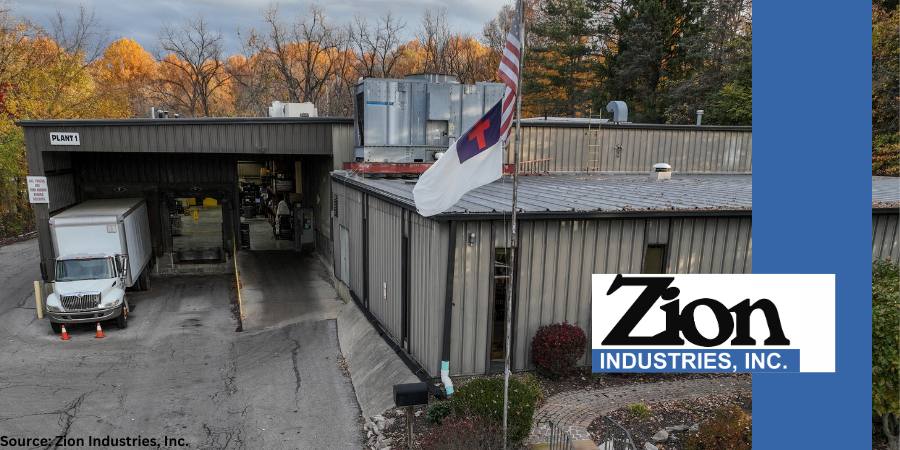
In a culture that does many things to a mere minimum standard, Bob Puls chose to found Zion Industries, Inc. on the standard of “Glory to God.” Seeking this high standard led the company to a specialization in induction heating, and since 1978, they have been building their knowledge on this topic. Today, the company’s expertise is demonstrated in the unique, customized services that benefit their own team as well as clients like Ford and Honda.
Zion’s ZSCAN induction scanner outfitted with full-service controls
Specialized, in-house induction equipment is one of the most interesting aspects of Zion Industries’ story. Across their three locations in Ohio, Michigan, and North Carolina, they have a combined total of over 30 induction machines (capable of frequencies from 3 Khz to 450 Khz and power levels from 30 Kwatts to 300 Kwatts) that were designed and built in-house. Supplementing these 30 unique machines is equipment for tempering and metallurgical inspection of all the heat treated products. The impact of this equipment is enhanced by the commitment to making their own tooling in-house, which decreased time and cost of the induction projects.
The company demonstrated their ability to create specialized solutions in-house when hardening safety critical, automotive industry parts. One instance of this was when Zion supplied latch striker parts that required a specific center case depth. This project was complicated by the fact that the part had a longer end geometry. To address this complication, the company created a completely unique, clamshell induction coil. The customization, however, did not end there. They also integrated the coil with fixtures that allowed for quenching and for sorting out suspect parts, all in the same operation.
The company offers personalized consulting services at their three locations. One aspect of these consulting services is training seminars that discuss the benefits and drawbacks of outsourcing induction heat treating versus bringing it in-house. Using the technical expertise of their 100+ employees, the company helps clients develop technology they may not currently have, but that may significantly benefit operations. The primary goal of offering consulting is to build a unique service around the client’s unique problems, rather than offering a one size-fits-all solution.
In the future, the company seeks to bring their customized, built-in-house induction equipment to new geographical markets. They will continue to upgrade their equipment and hope to integrate automation and robotics into their facilities. As Zion Industries spreads to new markets and grows internal operations, their success will continue because of their fixed focus: specialized induction heat treating.
Last week, Heat TreatToday wrapped up its third annual Heat TreatBoot Camp with a tour of a local commercial heat treating company, witnessing the operation of multiple vacuum furnaces, including the largest capacity vacuum furnaces in the United States.
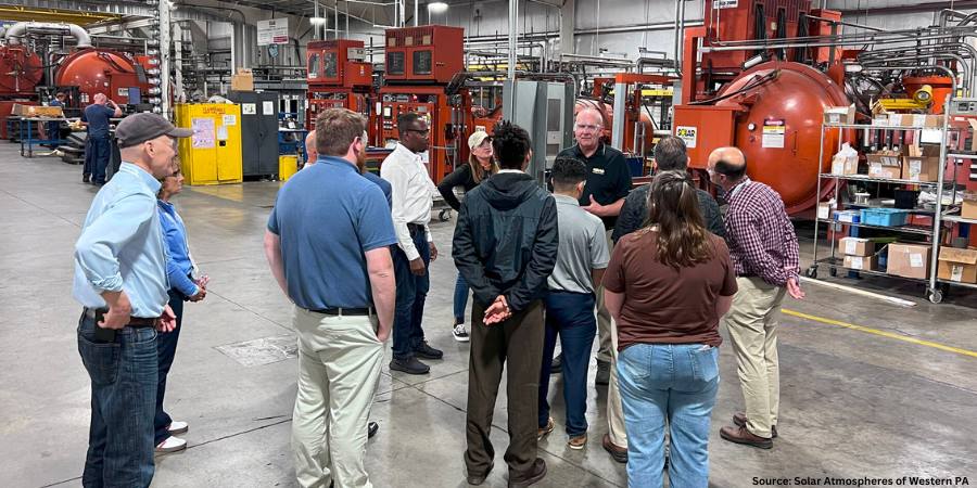
The overall sentiment from theHeat TreatBoot Campattendees was resounding gratefulness for and enjoyment of the visit to the 115,000 square-foot Solar Atmospheres of Western Pennsylvania facility, located in Hermitage, PA. For those newbies to the industry, it provided them the opportunity to experience a heat treat shop environment and connect what they learned during the sessions to how it looks in operation.
Heat Treat Boot Camp attendees in front of the NEO, one Solar Atmospheres’ vacuum oil quench furnaces
“Really great tour,” said Heat TreatBoot Camp attendee G. Eric Gisonno. “[I’m] so thankful to Solar and Bob Hill for spending time with us and allowing us to see them in action.”
Robert Hill, FASM President Solar Atmospheres of Western PA
Bob Hill, president of Solar Atmospheres, treated the 22 attendees to a comprehensive and fascinating tour which ranged from learning about the origin of the company to observing products in production process to seeing final completed parts. Attendees were in awe as they walked the floor taking in the daily production protocols. The tour concluded in front of the NEO, a vacuum oil quench furnace that earned Solar Atmospheres an accreditation from Boeing for its ability to oil quench alloy steels in accordance with Boeing’s specification BAC 5617. Those present were able to observe a part being vacuum oil quenched in real time.
Trevor Jones CEO Solar Manufacturing
Mr. Hill also provided an exclusive sneak preview of the company’s upcoming presentation, “The Future of Vacuum Oil Quenching is Now!,” which he and Trevor Jones, president of Solar Manufacturing, will deliver at the FNA 2024 show in Columbus, OH, this October.
Thanks to Bob Hill and the team at Solar Atmospheres of Western PA for their kindness and hospitality.
Main photo: Heat TreatBoot Camp attendeestouring Solar Atmospheres of Western PA
On just about any given Tuesday, Heat TreatToday features an article that aims to educate our heat treating readers — be it in a process, equipment, metals, analysis, critical parts, or more. On this Thursday, enjoy this sampling of Technical Tuesday articles from the past several months.
Case Study: Heat Treat Equipment Meets the Future Industry Today
How has one heat treat furnace supplier contended with modern challenges of manufacturing? In this case study about a shift away from traditional forms of heat treat, explore how vacuum furnace technology has more technological horizons to bound.
Figure 1. Construction and schematic furnace cross-section CMe-T6810-25
Several key features discussed are the various challenges that characterize modern industry; the differences between historical heat treat furnaces and vacuum furnaces; furnace features that can meet these obstacles; and a close look at what one equipment option from SECO/WARWICK can offer. Additionally, explore the case study of a process that resulted in the following assessment: All technological requirements have been met, obtaining the following indicators of efficiency and consumption of energy factors calculated for the entire load and per unit net weight of the load (700 kg).”
How do thermocouples work? How would you tell if you had a bad one? Those ever-present temperature monitors are fairly straightforward to use, but when it comes to how it works — and why — things get complicated.
Figure 2. Eric Yeager of Cleveland Electric Laboratories explaining the 101 of all things thermocouple
This transcript Q&A article was published in a print edition, but there was too much information to fit the pages. Click below to read the full-length interview, including the final conversation about how dissimilar metals create electromotive force (EMF). Included in the discussion is proper care of T/C and guidance on when it’s time to replace.
A Quick Guide to Alloys and Their Medical Applications
Figure 3. Sneak peak of this medical alloys resource
If you’re pining for a medical heat treat quick resource in our “off-season,” we have a resource for you. Whether you are a seasoned heat treater of medical application parts or not, you know that the alloy composition of the part will greatly determine the type of heat treat application that is suitable. Before you expand your heat treat capabilities of medical devices, check out this graphic to quickly pin-point what alloys are in high-demand within the medical industry and what end-product they relate to.
The alloys addressed in this graphic are titanium, cobalt chromium, niobium, nitinol, copper, and tantalum.
Resource — Forging, Quenching, and Integrated Heat Treat: DFIQ Final Report
How much time and energy does it take to bring parts through forging and heat treatment? Have you ever tried integrating these heat intensive processes? If part design, forging method, and heat treat quenching solutions are considered together, some amazing results can occur. Check out the report findings when Direct from Forge Intensive Quenching (DFIQTM) was studied.
Figure 4. Examples of DFIQ equipment
Forgings were tested, in three different locations, to see if immediate quenching after forging made a difference in a variety of steel samples. The report shares, “The following material mechanical properties were evaluated: tensile strength, yield strength, elongation, reduction in area, and impact strength. Data obtained on the mechanical properties of DFIQ forgings were compared to that of forgings after applying a conventional post-forging heat treating process.”
3 Top Tips for Brinell and Rockwell Hardness Tests
Figure 5. Testing hardness
Accurate hardness testing is a critical business for numerous industries, not least heat treatment. In this guide, evaluate “best practice” for getting the best possible reading for your hardness test with the most efficiency. These comprehensive tips include proper set up for test equipment and need-to-know information regarding the preparation and execution of both Brinell and Rockwell hardness tests.
In fact, while there are some practices that overlap, knowing the differences is critical to determine whether or not a piece has reached the appropriate hardness. For Brinell, grease may skew a reading so that “at 300 HBW the material may appear 20 HBW softer than it actually is.” On the other hand, the precision in measuring indentation depth (versus indentation width) makes it imperative to keep the surfaces clear of any contamination.
Trending Market Insights for Aluminum Thermal Processing
Figure 6. State of the North American aluminum industry
In this survey on recent and developing changes in the aluminum market, we asked industry players about the impact of trending technology and the overall state of the industry. Their responses to our questions in August 2023 described a steady and increasing melters’ demand; a limited, or lack of, business increase from additive manufacturing and 3D printing; the impact of — and response to — slow supply chains; the status of sustainability in the aluminum market; and how they plan to meet future market demand.
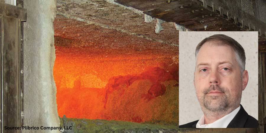
Heat treating aluminum presents a unique concern due to the operating conditions of high temperature, chemical corrosion, mechanical abrasion, and temperature variation. Guest columnist Roger M. Smith, director of technical services at Plibrico Company, LLC, examines the critical role the refractory lining plays in the success of manufacturing aluminum, why a refractory is susceptible to cracking under extreme conditions, and how to select and prepare refractory linings to achieve a longer service life.
A significant concern when manufacturing aluminum metal is the practical service life of the furnace. The service life is driven by the refractory lining’s ability to resist the various operating conditions within the furnace, such as high temperature, temperature variation, chemical corrosion, and mechanical abrasion. Ideally, a single refractory composition would be capable of withstanding all these conditions and readily available at a low price. Unfortunately, this is rarely the case.
Proper refractory selection is often about finding the best balance between price, properties, and performance for the given application and operating conditions. A refractory capable of high strength and abrasion resistance is often susceptible to cracking caused by extreme temperature variations, commonly referred to as thermal shock. However, a material capable of withstanding thermal shock without catastrophic cracking may be vulnerable to chemical corrosion. Finding the best balance of material properties for each zone in each furnace is important for maximizing the service life of a furnace.
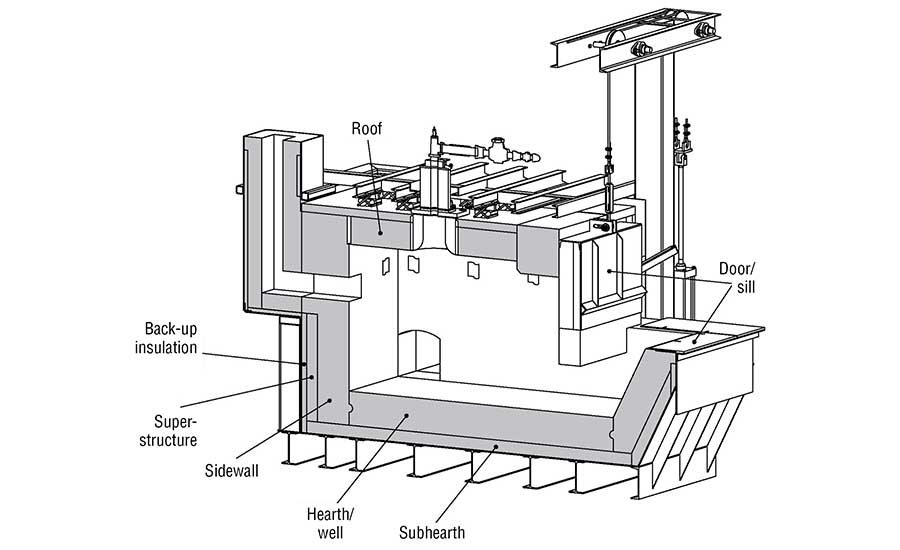
Figure 1. Schematic showing refractory lining in an aluminum furnace
Refractory Under Attack — Requirements for Melting Aluminum
The refractory lining in an aluminum furnace (Figure 1) must endure various chemical reactions that occur while the furnace is in operation. There are three separate regions to consider: above, below, and at the melt line. Above the melt line, the refractory must withstand attack from various alkali vapors. Alkali vapors can be produced from flux used in the aluminum and from the combustion products used to heat the furnace. Below the melt line, the refractory must withstand molten aluminum. At the melt line, the region commonly referred to as the bellyband area, there is a triple point where the refractory, atmosphere, and aluminum interact.
The refractory below the melt line comes in direct contact with liquid aluminum when the furnace is in operation. This contact can create a chemical reaction zone where oxides on the surface of the refractory can be reduced, such as silica (SiO2) to form silicon. Conversely, aluminum can penetrate into the refractory lining either through the same redox reactions or through infiltration due to capillary forces.
Aluminum forms corundum (Al2O3) when it oxidizes. This results in a change of the crystal structure from face-centered cubic to hexagonal, which causes a significant volume expansion. When corundum is formed inside the refractory lining, the change in volume creates cracks, which lead to more infiltration and more cracks until the refractory lining ultimately fails.
Wetting the Refractory
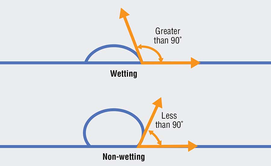
One method for reducing the reaction zone is to prevent the aluminum from “wetting” the refractory (see Figure 2). A liquid’s ability to “wet” a surface is defined by the contact angle of the liquid. When the contact angle between the liquid and the surface is greater than 90 degrees, then the liquid is said to wet the surface. When the contact angle is less than 90 degrees, the liquid does not wet the surface. A liquid that does not wet the surface is analogous to water beading on a car that has been freshly waxed. When aluminum does not wet a refractory, it is not able to react with the refractory and is not able to penetrate the lining.
Figure 2. Contact angle of the liquid demonstrating wetting vs. non-wetting
Various additives can be used to reduce aluminum’s tendency to wet a refractory. Some of the most used additives include barium, boron, or fluoride. They modify the surface chemistry of the refractory and reduce aluminum’s ability to react and penetrate. Using additives such as these greatly extends the effective service life of a refractory lining.
While non-wetting additives can be beneficial to extending the service life in areas where there is contact with molten aluminum, there are no benefits when not in aluminum contact. They do not protect from alkali attacks above the melt line. They do not enhance the abrasion resistance of the material. They do not improve the thermal shock resistance of the material. Furthermore, these additives are volatile. When exposed to temperatures above 1700°F (927°C), they begin to lose their effectiveness because they chemically react with other materials in the refractory and change. The additives can also be costly, which raises the price of the refractory compared to one with the same composition but without the additive.
The presence of non-wetting additives can have some negative effects on a refractory. Tests have shown that a 1% addition of a fluoride additive in a conventional castable can reduce the hot modulus of rupture (HMOR) by as much as 30% at 2000°F (1093°C). The effect can be even more significant in a low-cement castable. The loss in hot strength is likely attributed to the formation of a glassy phase induced by the additive. Fluoride and boron are both well-known glass formers and will form a glassy phase at the grain boundaries at high temperatures, which reduces the bond strength between individual grains and the overall strength of the bulk material.
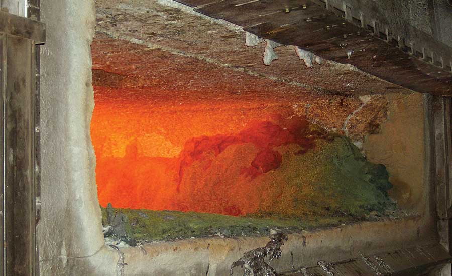
Figure 3. Refractory lining
Balancing Refractory Properties
The advantages and disadvantages of a refractory material should be considered when selecting materials for an aluminum furnace. The sidewalls of a furnace all come in direct contact with molten aluminum.
The upper sidewalls must be scraped to remove aluminum that splashes up to prevent corundum growth. The refractory selected for its sidewalls should be abrasion resistant to protect from mechanical scraping and non-wetting to protect from corundum growth. The hearth and well are submerged in aluminum, but they do not see the same level of abrasion as the sidewalls. The sub-hearth may see some molten aluminum but must also provide support, so a strong, non-wetting refractory should be used.
The door and sill will experience temperature fluctuations every time the door is opened, and they will be exposed to abrasion as the furnace is charged. Materials that are resistant to thermal shock and abrasion should be selected. The roof and superstructure need to be strong and resistant to alkali vapors. Backup insulation should be selected to reduce heat loss, but it should be of a composition that has moderate resistance to molten aluminum in case of refractory failure at the hot face.
In all these zones, the operating conditions of the specific furnace must be considered, and the balance of properties must be adjusted case-by-case. The primary failure modes must be identified, and materials should then be adjusted accordingly.
The Key to Refractory Selection
The operating conditions in an aluminum furnace require a refractory lining with different benefits in different zones. At the furnace door, the refractory can experience drastic fluctuations in temperature that can cause cracking. The upper sidewalls will develop scale that has to be scraped off, so the refractory needs to be abrasion resistant.
The lower sidewalls come in direct contact with molten aluminum and need to resist chemical attacks and aluminum penetration to avoid corundum growth. Finding a cost-effective refractory that can meet all these requirements is very difficult, but it can be done with sufficient research. Careful material selection that considers the needs and operating conditions of a particular furnace is important for maximizing the service life of a refractory lining.
About the Author:
Roger M. Smith Director of Technical Services Plibrico Company, LLC Source: Plibrico
Roger Smith is a seasoned professional in the refractory industry. With a master’s degree in Ceramic Engineering from the University of Missouri – Rolla, Roger has over 15 years of experience in the processing, development, and quality assurance of both traditional and advanced ceramics. He has a proven track record in developing innovative ceramic formulations, scaling up processes for commercial production, and optimizing manufacturing operations.
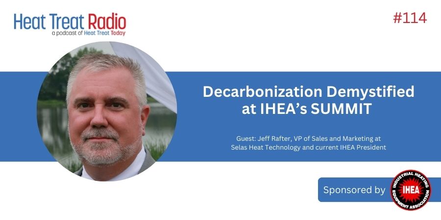
Listen as Jeff Rafter, vice president of sales and marketing at Selas Heat Technology and current IHEA president, discusses the upcoming IHEA Decarbonization SUMIMIT with Doug Glenn. Scheduled for October 28-30 in Indianapolis, Indiana, the summit will address the challenges and opportunities of decarbonization for manufacturers. Jeff highlights IHEA’s nearly 100-year history in industry education. The event will feature keynote speakers from the DOE, Oak Ridge National Laboratory, and John Deere, with a mix of technical and business content aiming to provide practical strategies for energy management and sustainability. Learn more in this episode of Heat TreatRadio, and learn more about this episode sponsor, IHEA, and their event at summit.ihea.org.
Below, you can watch the video, listen to the podcast by clicking on the audio play button, or read an edited transcript.
The following transcript has been edited for your reading enjoyment.
The IHEA Decarbonization Summit (01:03)
Doug Glenn: Jeff, when and where is the summit? And what was the driving force behind deciding to do this event?
Jeff Rafter: The IHEA Decarbonization SUMMIT will be at the Conrad Hotel in Indianapolis, Indiana, beginning on Monday, October 28, and ending Wednesday, October 30.
The drive to create this event arose because the IHEA membership had often commented on, and lamented, the frequent inquiries they get from the client base across all sectors of manufacturing; clients are looking for clarification on the ongoing changes of the U.S. energy infrastructure and, specifically, how to manage the requirement to reduce carbon dioxide emissions.
There is a lot that is changing quickly in the U.S. energy infrastructure around renewables, electrification, and low carbon fuels. he IHEA board felt that it was essential to assist manufacturing members by trying to clarify these topics in an interesting event that presented the information objectively and provided a diverse array of all the decarbonization pathways available to manufacturers today.
IHEA’s Qualifications (02:36)
Doug Glenn: For those who might not know what IHEA is, what makes it uniquely qualified to present such a summit?
Jeff Rafter: I am proud to say that IHEA is a very unique organization. Many trade organizations do not have the long-standing success in supporting members that this organization has. The composition of IHEA, which is close to 100 years old, was originally made up of heating appliance and heating component manufacturers, who have spent most of our history focused on industry education as a service to all the member companies.
We felt that this was the perfect organization to take up the topic of sustainability and decarbonization because we are education focused. From that background and that bias, we are leveraging thousands of years of experience over a broad array of manufacturing options from traditional fossil fuels through electrification. Our member companies provide a very strong basis to deliver real-world examples of how to deal with reducing CO2 emissions.
Doug Glenn: And if I am remembering correctly, IHEA actually has a standing history of cooperation and working with the DOE on different things in the past, correct?
Jeff Rafter: Very good point, Doug. If you look back in history, before “CO2 reduction” and “decarbonization” became buzzwords, we spent a lot of similar efforts working with government organizations, research laboratories, and third-party organizations around topics of NOx reduction and trying to create a cleaner basis of industrial, manufacturing, and energy. In addition, we have always spent our time helping with business concerns regarding efficiency, not only operating successfully heating processes and appliances, but also making manufacturing more cost effective.
Keynote Speakers (04:44)
Doug Glenn: And speaking of the DOE, I see that there are some pretty high-profile speakers coming. The keynote speaker is Dr. Avi Shultz, from the U.S. DOE, and he is on the Industrial Decarbonization Initiative. Other speakers include Paulomi Nandy from Oak Ridge National Lab, Jeff Kaman from John Deere, and Tim Hill from Nucor. Can you give us a sense of what these folks will be talking about?
Dr. Avi Shultz Director U.S. Department of Energy (DOE) The Industrial Efficiency & Decarbonization Office (IEDO)Paulomi Nandy Technical Account Manager, R&D Assistant Staff Member Manufacturing Energy Efficiency Research Analysis Group (MEERA) Oak Ridge National Laboratory (ORNL)Jeff Kaman Manager, Energy Supply and Sustainability John DeereTim Hill General Manager Sustainability Solutions NucorSpeakers at the IHEA Decarburization Summit
Jeff Rafter: Doug, we are very excited to have the diverse mix of speakers that will make up the summit presentations. With Dr. Schultz and Miss Nandy, we are very excited to be providing a third-party opinion — government organizations and research laboratories — and they will be presenting on their views of the trends for the future of sustainability and decarbonization.
When we move to some of the other presenters like Tim Hill from Nucor and Mr. Kaman from John Deere, we also wanted members and attendees to take away from the summit real-world experience. These are not imagined or planned changes. We wanted companies that had actual experience with decarbonization — who had even taken actions towards net-zero positions — to share with attendees exactly how they approached the challenges.
Because, of course, some of the issues around sustainability are that it comes at a cost.
And how do you fund that? How do you research that? Where do you look for grants, and how do you make the business case towards decarbonization or any sustainability action for that matter?
Finally, adding to those two bodies of participants, we have a number of presenters speaking about real-world solutions today. IHEA’s view on decarbonization and sustainability is that there is a very broad set of pathways that you can take today with inexpensive, readily available technologies all the way out to longer term solutions like full electrification of processes.
There is more than one way to approach this challenge and do the responsible thing in manufacturing, which is to address our CO2 production globally.
Is Electrification the Only Answer? (07:25)
Doug Glenn: You mentioned electrification. When people hear decarbonization or sustainability, they often think electrification. There may be a lot of people listening saying, “I am primarily combustion. Should I be going?” Are only electrification solutions going to be presented? Or are combustion solutions going to be presented as well to help with the decarbonization?
Jeff Rafter: The answer to that question is, “Yes, you should be going, regardless of whether your focus and your background is in traditional fossil fuel combustion or electrification.”
The summit will contain a very balanced approach of different technologies, presented with no bias. The goal of this summit is providing education to help business leaders make better decisions around their energy management and their environmental concerns.
With that said, when we look at the body of what is available in the agenda, electrification is an important topic. But as a lot of people recognize, some portions of electrification are just relocating to a different fossil fuel further away from the point of use whilst other electrification options linked to renewable energy sources truly can come close to net-zero production of CO2.
IHEA’s view is that there are many sustainability pathways that we can all investigate or pursue.
Some pathways maintain fossil fuel basis. Some industrial processes will be challenged to move to an electric heating source. And then for other processes, electrification is the cat’s meow. So it is that broad sweep of diverse technologies that everyone needs to be educated on to make better decisions when the time comes.
Who Should Attend the Summit? (09:21)
Doug Glenn: How technical will the summit be; do I need to know heavy engineering, metallurgy, and things of that sort? And who should come?
Jeff Rafter: Traditionally, a lot of IHEA’s educational content has been directed at a technical audience; it was technical education about how various energy sources and heating appliances work, how to comply to code, and how to approach the application of that equipment safely. In this particular summit, we have changed course a bit in that we did not want this event to be a technical conference.
The idea of this summit was to make it a business conference because that is where most of the challenges exist when we look at sustainability efforts.
The content that will be presented is a pleasant mix of some technical topics because we have to get a rudimentary understanding of how these different technologies work. However, we are spending just as much time in the presentations addressing business concerns: How do you fund these various actions? Where can you find available grants? What are real-world examples of how other companies have approached sustainability or have begun an initiative internally? How do you get the support and the decision-making decided while moving in the right direction? When you look at the agenda that will be posted on the IHEA website, you will see that the topics range broadly from some technology presentations to real-world business concerns and how to make those business decisions.
Agenda for IHEA Decarburization Summitt, Monday – Wednesday, October 28-30, 2024, in Indianapolis, Indiana
Doug Glenn: How much fun have you had putting this summit together?
Jeff Rafter: I would happily report it has been a tremendous team effort.
I am very proud to say that a lot of IHEA member companies and third parties have stepped up to help us construct this event. We are really looking forward to it being a valuable event that provides a lot of information and important takeaways for participants.
Doug Glenn: I know you have put a lot of work into it. I have watched you do this over the last year and a half, and you have done a great job coordinating it.
Closing Remarks (12:34)
Jeff Rafter: I would just like to say in closing, for anyone who is thinking about coming to the IHEA Decarbonization Summit, please do. This is a very important topic for manufacturers, and you really need to take the approach of not waiting. It is time to get in front of changes in our energy infrastructure and the need to decarbonize some manufacturing processes. This is a great way to get educated and start your plan.
Doug Glenn: And I did remember one other motivation: If you are looking to stay at the hotel where the summit is held, the cutoff date for the hotel (you can still get into the summit even if you do not hit this cutoff date) is October 7th. So anyhow, appreciate it. Jeff, thanks very much for your time.
About The Guest
Jeff Rafter Vice President of Sales and Marketing Selas Heat Technology Company, LLC Source: Selas Heat Technology
Jeff Rafter is vice president of sales and marketing for Selas Heat Technology in Streetsboro, Ohio, and has a rich history in the combustion industry, including Maxon Corporation. Jeff has 31 years of industrial experience in sales, research and development, and marketing; combustion application expertise in process heating, metals, refining, and power generation; and 13 years of service on NFPA 86 committee. He holds patents for ultra-low NOx burner design. Additionally, his company, Selas, is an IHEA member, and Jeff is the current president of IHEA as well as one of the driving forces/coordinators behind the upcoming Decarbonization Summit at the Conrad Hotel in Indianapolis, October 28-30.