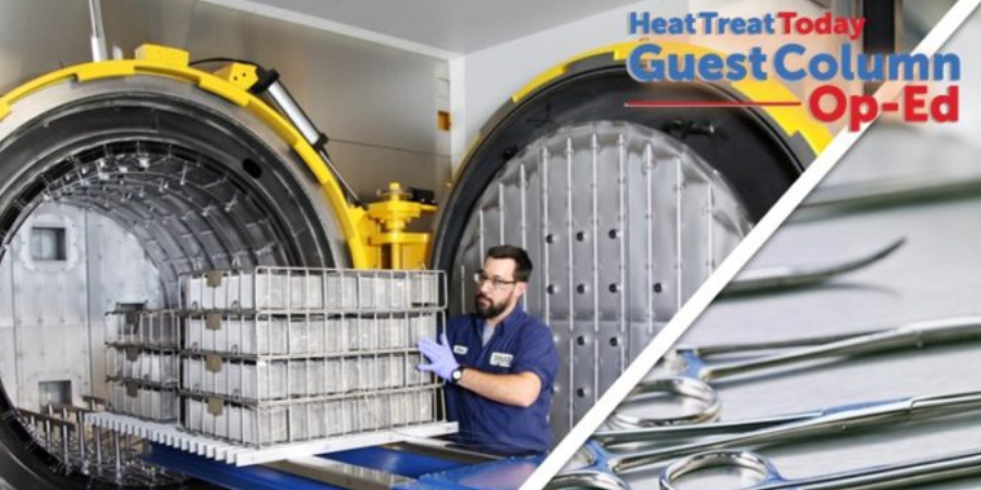
Medical devices, medical tools, and prosthetics all have a long history with heat treating. As we look to the future, the materials industry and the advancement of AM into the heat treat industry is moving at lightning speed.
In this article by Trevor Jones, CEO, Solar Manufacturing Inc., see why vacuum furnaces are excellent choices for accurately providing the necessary process parameters for this incredible medical technology that can provide people with mobility, function and independence to improve their quality of life.
This original content column was originally published in Heat Treat Today's Medical and Energy magazine, December 2020.
Trevor Jones CEO Solar Manufacturing, Inc. Source: Solar Manufacturing, Inc.
Thermal processing of metallic alloys is the backbone of the heat treating industry. Speaking of backbones, the human spine, a critical part of the human body, can now be replaced with an additively manufactured and heat treated prosthetic metallic alloy spine. Medical devices, medical tools, and prosthetics all have a long history with heat treatment. As we look to the future, the materials industry and the advancement of AM into the heat treat industry is moving at lightning speed.
AM parts require precise heat treating especially, when it comes to atmosphere control, temperature uniformity, and flexibility. Vacuum furnaces are ideal for accurately providing each of these process parameters. Let’s take a look at each of these heating treat parameters a little more closely.
Atmosphere Control
Vacuum, by nature, is a neutral atmosphere which, in part, means it has no carburizing or decarburizing potential. Therefore, the surface of the parts that is directly exposed to the vacuum atmosphere cannot gain or lose the base carbon content of the alloy. Additionally, vacuum is practically void of oxygen. If the parts were exposed to oxygen at the elevated processing temperatures, the surface of the parts would become oxidized. In minor cases, a superficial oxidation layer would be the result. In more severe cases, the surface could experience alloy depletion and diffused oxygen.
This is particularly important when processing titanium alloys, which are inherently more sensitive to carbon, oxygen, and nitrogen. When titanium is exposed to any of these elements, a metallurgical phase called “alpha case” can develop on the surface of the titanium and diffuse inwards towards the core of the part.
In most applications, the alpha case is undesirable, and precautions should be taken to prevent it.
Vacuum processing can also provide an atmosphere where an elemental substance, like nitrogen, can be kept in balance with the parts being processed. For example, if an AM part intentionally contains nitrogen, processing this part in a deep vacuum may remove some of the nitrogen base content in the part. To prevent this from occurring, partial pressure nitrogen in the vacuum furnace keeps the nitrogen in equilibrium. The surface condition of these parts is extremely important especially if the AM parts will be implanted into the human body.
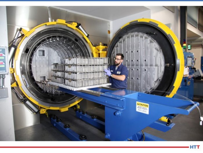
The medical processing room at Solar Atmospheres. Source: Solar Manufacturing, Inc.
Temperature Control
The working zone of the furnace encompasses the parts being processed. It is critical that this entire working zone volume be thermally uniform to achieve predictable and consistent results. If any area of a working zone is cooler or hotter than the temperature of another area, it may negatively impact the heat treatment results including difference in mechanical properties and dimensional changes of the parts. For example, if the process is stress relieving and the parts were not subjected to high enough temperature for the requisite time, the parts may still contain some residual stresses.
Residual stresses can have various negative consequences during manufacturing, including cracking and part distortion – during build and finish machining. Tensile residual stresses in finished parts can also reduce fatigue and corrosion performance.1 A failure of a medical implant in the human body would be disastrous if it could have been avoided with proper heat treating!
Medical Instruments Source: ??
With proper design, vacuum furnaces can provide very tight temperature uniformity of ±5°F with direct part temperature monitoring throughout an entire working zone over a broad temperature range.
Flexibility
The vacuum furnace is extremely versatile in the infinite amount of process variables that are available to be adjusted, including heating rates, soaking temperatures, soaking times, atmospheric conditions, and cooling rates. All these variables can be adjusted to provide precisely what is required for a given alloy to optimize the heat treatment needs for the part being processed. To meet the need of the modulus and the strength and fatigue characteristics of a medical implant, AM technology can adjust the mechanical properties of the implant by changing some of the parameters in the processing.2
One of the many steps in the AM process is heat treating, and vacuum furnaces provide the flexibility that can be tailored to the alloy and heat treatment required. Having an AM prosthetic custom vacuum heat treated to fit the human body, could be the key to its success.
Vacuum furnaces and their unique heat treatment processes are ideal for providing the atmosphere control, temperature control, and flexibility that are essential for AM medical devices, tools, and prosthetics. As the AM market expands and the technology advances, vacuum furnace technology will continue to be integral in fostering that growth.
About the Author:
Trevor Jones began his career as the project engineer at Solar Atmospheres commercial heat treating on their Research and Development Team, concentrating on the improvement of vacuum thermal processing equipment and the development of new processes. He is currently the CEO of the Solar Manufacturing, Inc., a division of the Solar Atmospheres Family of Companies.
GEBERIT Group, a European leader in sanitary products, will expand their annealing capabilities with two vacuum furnaces at their production plant in Ozorków. Both furnaces have larger working spaces than the standard: 900 x 900 x 1200 mm (HxWxL) to 900 x 900 x 2400 mm. These changes will allow the manufacturer to double the efficiency of the furnaces in one technological process.
As GEBERIT builds its independence by investing in heat treatment processes, some of the processes that they had carried out in traditional atmospheric furnaces will now be performed in these modern Vector vacuum furnaces supplied by North American SECO/VACUUM‘s parent company, SECO/WARWICK.
Sławomir Woźniak CEO SECO/WARWICK Source: secowarwick.com
“We chose the SECO/WARWICK Vector furnaces,” commented Mirosław Spasiński, head of the Technical Department of GEBERIT in Ozorków, “due to the guaranteed quality and efficiency but also the high cleanliness of the surfaces of the processed details, which is very important to us, as the elements are displayed in open GEBERIT sanitary installations, thus aesthetics play an important role.”
“An individual approach to the furnace design” notes Sławomir Woźniak, CEO of SECO/WARWICK Group, “is a project that requires expert engineering knowledge. [Our] engineers have the knowledge and experience that are needed to adjust the technology and its parameters so that it ensures the safety and failure-free operation of the device, but above all that the solution meets the expectations and needs of the client.”
Heat Treat Radio host Doug Glenn continues his conversation with AMS2750F expert Andrew Bassett. This final discussion revolves around changes in temperature uniformity survey (TUS) specifications.
Below, you can either listen to the podcast by clicking on the audio play button, or you can read an edited version of the transcript.
The following transcript has been edited for your reading enjoyment.
Doug Glen (DG): In this episode, Andrew Bassett and I have our third and final conversation about AMS2750F. Andrew Bassett is president of ATP and directly contributed his expertise to the latest revisions of AMS2750. If you haven’t heard the previous two episodes, you can find them by Binging or Googling Heat Treat Radio or by simply typing www.heattreattoday.com/radio into your browser.
In the first episode, you and I did some talking about just the AMS2750 generally; what it was, how it’s done, who was on the committee obviously, the fact that it’s not just a minor rewrite, but that it’s a major rewrite and then specifically in that first episode, we talked about thermocouples and calibration. Once we were done with that, we went into the second episode where we talked about system accuracy tests.
Andrew, again, tell our listeners who was involved on the committee. I know that from our perspective, the good folks over at GeoCorp had James LaFollete on the committee and I know Doug Shuler from Pyro Consulting was on there, but who else was on the committee that was responsible for putting this revision F together?
Andrew Bassett (AB): We had Marcel Cuperman from PRI (Performance Review Institute). He is one of the lead staff engineers for the NADCAP heat treat task group. We had Doug Matson from Boeing. Doug Matson, after the release of Rev F went into retirement. He has still been very active on any questions that have been arising with the Rev F. He’s retired, but he’s still in the loop with the specification. We had Brian Reynolds from Arconic. Again, we were looking for various people within the industry, so Brian Reynolds gave us a perspective from the raw material suppliers. We also had Cyril Vernault from Safran Aerospace. We wanted some European influence on the specification, and he is also the task group chairman for heat treat. We had a good, well rounded group of guys that were experts on this, to try to get this next revision put together.
DG: And yourself, of course. Let’s not forget that.
AB: I always like to say that I wrote the good stuff in there.
DG: Before we jump into TUS specifics and some of the major changes there, I want to hit just briefly on training. You and I were talking about this before we hit the record button. The fact of the matter is, there are several different training courses out there. Obviously, these three episodes ought to be helpful to you. A direct call to your cell or to Aerospace Testing and Pyrometry probably wouldn’t be a bad idea if somebody needed help with it. Does ATP also provide a training course?
AB: Yes, we do. We’ve always prided ourselves on providing AMS2750 training. Our training has always been customized to what our customers requirements would be, so every course is not the same. We like to take it to more than just AMS2750. You have to remember, there are other aerospace primes out there that have their own pyrometry requirements. For instance, GE Aviation has their own pyrometry requirements, P10TF3. Rolls Royce has their own pyrometry requirements. Or Pratt & Whitney might have some other things that need to be addressed. We actually sit down with our customers prior to any training and kind of take out the information that is needed, and then we perform the training onsite at the client’s facilities. So that if any other questions arise – “Hey, you’re talking about the SAT stuff” – then I can say, “Hey, let’s go for a field trip” and we can walk right out to the customer’s equipment and kind of demonstrate how to do, let’s say, a proper SAT or proper calibration. Again, we’ll cover various different specifications. For instance, one thing we like to do is find out what types of heat treating they’re doing. If they’re strictly a vacuum heat treating, I’m not going to talk about any of the aluminum requirements. There are some pyrometry requirements when it comes to aluminum, but we’ll talk about vacuum gauge calibrations, which is not covered under 2750, but is covered under AMS2769. Again, each one of our courses is customized to what our client’s needs are.
So, yes, they can feel free to reach out to us. There is myself and Collin Thomas who is an ex-NADCAP auditor for the two instructors for the course, and we’re more than willing to help out with that at any time.
DG: And just so everyone knows, at the end of this podcast, we will mention a couple of other companies and resources that you can go to for training on AMS2750F. I would like to mention, though, just a little self-serving note – and I did this with Google just a minute ago, though I don’t know that it will work on everybody’s location and what not… I Googled “AMS2750F” and Heat Treat Today came up as the second item with an article that we posted back on July 21st called AMS2750F expert analysis of which, Andrew, you were one of the contributors. We had five contributors, I believe, to that article, Doug Shuler being one of them, Peter Sherwin from Eurotherm being another, yourself being one and we had two others, Jim Oakes from SSI and Jason Schulze. I think you had to answer two or three questions and we compiled that. So that’s also a good resource to go to, if you have a moment to do so.
Let’s jump into temperature uniformity surveys (TUS). As we’ve done in the past, basically what we’re doing is asking you, “what were the major changes in this area?” So we’ve broken TUS into five basic questions. Let’s hit the first one now. Looking for the major changes in modifications and repairs section, tell us about that.
AB: In Rev E (the previous revision), there were two sections broken out called furnace modifications and furnace repairs. We put in there the caveat “but not limited to the following things.” If you replaced a hot zone in a vacuum furnace, or you changed thermocouple locations, these would trigger a major modification where you would have to do an initial uniformity survey. We basically took out the repairs function and just left in modification. If any kind of preventive maintenance, or some sort of maintenance function that is done, that would be considered a repair, it’s going to be up to the user’s quality organization to determine if any other testing is going to be required. For instance, if they replace a door seal around a door, quality is going to have to get involved and ask, “Do we need to do a uniformity survey?” What I always tell suppliers out there that are compliant with this is, get with your maintenance team, because the maintenance team typically will know whatever repair they did will have a major impact to maybe a uniformity survey. At that standpoint, repairs will have to be documented, as always, and then quality is going to have to sign off and ask, “Do we need another calibration, an SAT or a TUS?” We’ve put the onus back on the users now to determine if a test needs to be conducted. And then they’re going to have to defend that if they have an audit.
It was kind of silent in the previous revisions of the spec, but it was kind of mentioned that when you move a piece of thermal processing equipment from one corner of the building to the other corner of the building, that you were going to be required to do an initial uniformity survey. I brought up to the team, that these days, they actually make furnaces and ovens with wheels on them. This is for cellular manufacturing. If they have wheels on them to be moved to different locations, it again will have to be on the onus of the quality department to determine if another uniformity or initial survey needs to be done. Maybe they do a quick test on the furnace to make sure it’s within the same realm as the previous testing. We did say that initial TUS may be waived if the furnace is designed to be portable.
Some of the other major changes/modifications were people were always thinking if you changed your control thermocouple, when you replace it with a new one, that you have to do an initial survey. We always said no, you don’t have to do that as long as you put it back in the documented location. But I did see a problem with this when if they change the type of sensor, basically the thickness of the sensor. Maybe they went from a 3/16th sensor down to a 1/8th sensor. Well the 1/8th sensor is going to be more sensitive to temperature change and that could have a major impact on the uniformity. Or if they went from a hot junction that was not exposed to an exposed junction, this again increases the sensitivity. So we added in that as a major modification. If you do change that type of scenario on your thermocouples, then yes, you’d better do an initial uniformity survey.
And lastly, since we’re getting more and more advanced control systems, if you change the PLC logic, the PLCs that control a vacuum furnace or any other type of thermal processing equipment, then you better do an initial uniformity survey. So we kind of beefed up a little bit of the major modifications to address some of the newer technology that is out there.
DG: You said a lot of that was up to the quality department? Is that true, for example, when you went from a hot junction to not? Is that still up to the quality department?
AB: No. That’s now been changed under the major modifications that would trigger an initial uniformity survey. Changing from different types of sensors is not a repair, that is a modification.
DG: How about the way vacuum furnaces and the TUS’s need to be performed there? What were the major changes?
AB: There was really only one major change that we changed for when you conduct a survey on a vacuum furnace. Before, all you had to do was just do your typical uniformities within your temperature ranges for your qualified range of use and your vacuum pressure. If you had a diffusion pump, it had to get below one micron and then just do your survey. But then, I think it was Dr. Shuler, that brought up the idea that said, if people use a back fill gas or use partial pressure, maybe they just need to have one test under partial pressure.
At first, we got a lot of push-back from the suppliers on that saying this is going to cost them extra money and they would have to do an extra test. And we said, no, this is just part of your routine temperature uniformity survey schedule. We’re just saying, at least on an annual basis, you choose a single operating temperature within a defined partial pressure range that you use during production. We just want a survey done that way. You get to choose what gas you’re using, if you’re using argon or nitrogen. The thought process behind this was, if you had a needle valve that maybe was leaking and creating a cold spot in your furnace and you didn’t know about it, it’s more of a preventive thing to ask are those needle valves leaking and are you getting a cold spot in your furnace that you don’t know about. That’s all we’re asking, is just for one survey to be done in any one of your single set point temperatures with any partial pressure gas in the range that you define as your partial pressure. Once we explained it that way, we were able to get over that hump and move forward.
DG: It wasn’t as onerous as it initially sounded, apparently.
AB: Yes, I think the wording in the original draft sounded like it was going to be an extra survey, and I can understand the pushback from the suppliers. We explained that it was not an extra survey, it’s just one during your regular routine survey.
DG: Right. It replaces another one.
AB: Correct.
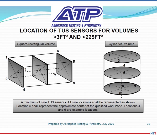
DG: Question 3. Location of the test thermocouples when you’re under 3 cubic feet.
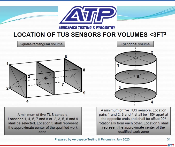
AB: This was something that I always had an issue with in AMS2750, in the previous revision. How it was stated was that when you have a furnace less than 3 cubic feet, you can do a survey with five sensors. And it said that the five sensors shall be placed in the corners. Well, in a cylindrical furnace, you have eight corners, so what five corners do you choose? My understanding was that when NADAP PRI was teaching their pyrometry course, it was basically the central plane of the furnace. So you would have two thermocouples in the front that were in the center plane and then two in the back in the center plane and one in the center.
And I said, that doesn’t really work so well because you’re not really getting what’s on the top of the furnace or the bottom of the furnace. So, what we ended up doing was putting some new diagrams in the specification that showed that you’re going to go opposite corners. Let’s say you’re going to put one thermocouple in the top left corner in the front and then diagonally across from that will be one in the bottom right corner. Then in the back you would reverse those. So we are covering the top and bottom of the furnace. And the last thermocouple will be in the center. We spelled out a little bit better way of testing these smaller furnaces.
Source: ATP
In a cylindrical furnace, it is stated that those thermocouples should be 180 degrees apart. Again, the NADCAP course would basically put five thermocouples in the center plane of a cylindrical furnace. And we said, no, we want two thermocouples on the top directly 180 degrees apart from each other and then two on the bottom, again, 180 degrees apart from each other, but they should be offset 90 degrees from the top one. You’re getting a better test of your full work zone dimension. I’ve always been doing these testings with these small furnaces in this method because that’s actually an older requirement from an old Boeing specification; the old BAC5621 actually spelled it out this way. We kind of adopted the old Boeing requirement of the smaller furnaces to show a better test for your small furnaces now.
Source: ATP
DG: Right. And let’s be clear, that is for a 3ft3 or smaller furnace. I assume, over 3ft3, you’ve still got nine thermocouples.
AB: Yes, greater than 3ft3 and less than 225ft3, you’ve still got the nine sensors. Once you get above 225 ft3, then the formula is in place in 2750F that spells out how many more thermocouples. I believe we don’t allow it to go past 40 thermocouples in some of those big monster furnaces.
DG: Let’s talk about aluminum for a little bit here. We’ve got radiation test surveys in aluminum furnaces, anything above 800°F; let’s talk about that.
AB: This is actually a surprise that this didn’t get some more pushback when we were putting the drafts out there. Originally, in previous revisions, it said all aluminum solution heat treating furnaces where the heat source is located in the wall, you had to do what’s called a radiation test survey. But we’ve changed the requirement to say all aluminum alloy thermal processing equipment used above 800, also with the heat source located in the furnace wall, ceiling or floor. This is a game changer because this will now put those aluminum vacuum braze furnaces into play. This was typically only a requirement for solution heat treating of aluminum alloys, but now it’s going to be for aluminum brazers. I’m very curious of how this is going to work. A radiation test survey is basically you have to have one 6061 aluminum panel that is 12 inches square with a test thermocouple peened into the middle of it and there is one panel for every 10 cubic feet of wall area. Basically, what we’re looking for is if there is any kind of direction radiation of heat to an aluminum panel as your panels are going to get extremely hot. What they’re looking for is eutectic melting. All aluminum heat furnaces, it’s required by AMS2770 which is the aluminum processing spec that says if you’re processing aluminum, there can’t be any direct radiation to the parts. But in a vacuum furnace, how is it heated? Direct radiation. I’m very curious as to how this is going to play out for those suppliers. Again, I was really surprised there wasn’t a whole lot of pushback from the aluminum vacuum braze facilities that have these types of furnaces that are now going to be required to do this test. It’s going to be interesting how that plays out once 2750 is in full force for everybody.
DG: Yes, and I guess we ought to say that it is not always radiation in a vacuum furnace. If you don’t have back fill gases, ok, it’s going to be all radiation. But if you’ve got some convective heat going on with back fill gases, that is possible. It doesn’t change the point that we’re making here. This is something for people to be aware of if you’re working with a vacuum furnace above 800°F, you’re doing any type of aluminum, then you’ve got a new requirement to do this radiation test.
AB: Yes. It’s the change of the words of ‘solution heat treating’ to ‘all aluminum alloy thermal processes.’
DG: Last question of the five. Documentation requirements. You mentioned there have been some changes. Tell us about those.
AB: We made a few changes to the documentation requirement. Basically from the standpoint of Rev E, we left everything from the original requirements in there, but people were unfamiliar with right after the section that talked about documentation. (The funny thing is we had to change it from reports to documentation. There was somebody that said we don’t want to call it a report because that quantitates that it has to be all in one package, we want to call it documentation. So we appeased that one.) Anyway, in Rev E, it was not part of the documentation records, but should be accessible on site, which were the control instrument tuning parameters, the PIDs or the proportional band reset rate, depending on the instrument manufactures, that those had to be documented for each thermal processing equipment. We thought this is being missed. There are a lot of places that I’ve been to where they don’t even know what the tuning parameters are. So we said from now on you’re going to have to document that in your TUS reports.
It also required to have a diagram of your TUS thermocouple location. That has always been a requirement, but we also now require you to show where the control thermocouple is placed and if you have any recording sensors. If you have type A instrument A or C instrumentation to have the high and low, those would have to be denoted on the diagram for part of the documentation package. We want to make sure that the supplier is aware that we don’t just need to see where your nine thermocouples are located, we also need to see where the control is and any applicable other sensors in the furnace that qualify for A, B or C.
We also want to find out, too, what type of atmosphere is being used in the furnace. Is it air? Is it a vacuum? Are you putting it under carburizing? You now have to list the atmosphere that was done during the testing as well. And then we’re also saying that the TUS test instrument that you’re using, you have to let us know what the correction factors are, even if you electronically apply them to the TUS instrument. You’re allowed to put in the correction factors prior to starting the TUS for your test instrument. A lot of people are saying it’s already been put into the recorder, I don’t need to document it. But we’re saying we still need to know what that correction factor is. So you need to document what those correction factors are.
There are two other things that are new to the documentation requirements. If you have types A or C instrumentation, again with the hot and cold thermocouples placed in there from the last uniformity survey, there shall be an analysis done to make sure that those locations have not changed. There are some requirements in Rev F that say if your uniformity survey is half your uniformity tolerance. In other words, if you’re testing for ∓10 and your final results come out less than ∓5, you can make an easy statement that my survey is within ∓5. No relocation of my hot and cold sensors are required. But you have to do an analysis of those two sensors for types A and C.
[blockquote author=”Andrew Bassett” style=”1″]We also want to find out, too, what type of atmosphere is being used in the furnace. Is it air? Is it a vacuum? Are you putting it under carburizing? You now have to list the atmosphere that was done during the testing as well.[/blockquote]
The other change deals with more of shaker type furnaces or continuous type furnaces, we call them continuous or semicontinuous furnaces. You have to list out what the traversing speeds are during your uniformity survey, maybe whatever your bump rate is for your shaker or the traverse rate. Then you’re going to have to recalculate what your work zone is. With a continuous type furnace, obviously your work zone will shrink the faster the belt goes through the furnace. There needs to be a recalculation of the work zone dimensions based on the survey based on what the belt speed should be.
And then lastly, like we’ve done with all the other documentation, if your service is being performed by a third party, the quality organization of the third party must also approve the reports as well.
Those are the major changes when it came to the documentation for temperature uniformity surveys.
DG: Basically, we’ve hit on three major areas. The first episode – thermocouples and calibration, the second episode – system accuracy tests, and this episode – temperature uniformity surveys. Are there any other odds and ends that you think our listeners should know about?
AB: Absolutely. There are a couple last minute things towards the end of this specification that already passed all the testing requirements.
The biggest pain when it came to Rev E is that we had the requirement for rounding, and that was to the ASTME29 method. That caused a lot of problems. I think we put a number on all the thermocouple suppliers because typically the thermocouple suppliers – when they’re doing their calibration of thermocouples – put everything into Excel. Well, Excel rounds .5 up, like we all learned in grade school. But, E29 doesn’t like that. They like to have if your next significant digit is odd, it rounds up; if it’s even, it stays the same. That put a little hamper on all of the thermocouple guys and we kind of didn’t think that one through.
So, now we’ve changed it in Rev F. The methods that you can use are ASTME29 using the absolute method, that still can stay the same, or you can use an equivalent international standard such as ISO 8001 rule B which is .5 round up, or you round to any commercial spreadsheet, in other words .5 round up. As long as you have documented procedures and you have to use it in a consistent manner. I should say we’ve relaxed the rules, so now you can choose what kind of rounding method you want to use.
We wanted to make sure that we spelled out, too, that all the tolerances in 2750F, if you look at Rev F compared to Rev E, all the tolerance requirements, we used to say plus or minus 10, now it says plus or minus 10.0. It’s an absolute. If you have a survey that you do that is 10.2 and you want to try to round that down, you can never round anything back into compliance. If something does fall out of tolerance by a 10th of a degree, or whatever, you cannot using the rounding function to bring it into compliance.
We addressed a hole that was left in Rev E on your test interval extensions. In previous revisions, we forgot about adding bimonthly and every four months, how many days you can go past an extension for a due date, so we finally addressed that in this revision. It used to be Table 10 and now it’s Table 25. The only thing that’s added onto this is if you do use an extension for any reason, there must be a written justification approved by the user’s quality organization. It can be as simple as: my test came due on Sunday, but I came in and did the test on Monday. You’re just going to have to write a note saying the due date was Sunday and you did it on Monday. You just have to write some justification of that.
Lastly, and I think this is a big thing, as well, is under the quality assurance provision. It is basically the section that says what happens if you have a pyrometry failure and so on. We didn’t change anything in there except two years after the release of Rev F, any third party pyrometry service organization must have a quality system approved to ISO 17025. Also, the scope of accreditation shall include laboratory standards and/or the field services applicable.
Third party service providers, two years after the release, will now have to be 17025 accredited. If they are, there is also no procedural oversight from the supplier. For example, since we’re 17025 accredited for our laboratory, we actually hold two different accreditations, one for our laboratory and one for our field service work for calibrations for uniformity surveys and system accuracy testing. Now, since we are third party accredited, our clients will not be required to have any oversight on us. Personally, I don’t think that’s the best option; I think the supplier should still be able to audit us and look at our procedures to make sure it’s compliant with the industry standards. But according to Rev F, there is no more oversight if we’re third party accredited.
I wasn’t a big fan of adding this in. Again, you would think people that are 17205 like ourselves would be happy to have this in there as it might weed out some other companies, but I’ve actually worked with some really good smaller shops – a two-man father and son that’s located in New York, and then a gentleman in California that is just a single guy, and these guys are very versed in the specification and do thing right. Unfortunately, now they’re going to have to be 17025 accredited. I talked to one of them and he said, “This may put me out of business. I don’t know if I can afford swinging this. I do a good job.” And I said, “I know, I’m trying to fight for you on this,” but it ended up going in. At least we put the caveat that they have two years to get it down, so it’s not something immediate.
DG: Yes, that is the danger when you start requiring certain accreditations, licenses or whatever. It’s typically the small guy that takes the beating. That’s too bad, but that’s the way it is… I shouldn’t be so flippant about that, should I? It is too bad!
AB: I really struggled. Originally, the first draft was going to be immediately, and I said, no, let’s put a moratorium on it for at least two years so people can queue up for that.
DG: I guess the moral of the story for the end user is within two years you need to be asking your third party survey companies/accreditation folks, whoever is coming in to do your pyrometry and whatnot, if they have this 17025.
Anything else? Any other odds and ends?
AB: The last thing I want to add about the 17025 is that this is only for third party suppliers. We’ve received questions like, We do our pyrometry internally, do I have to go get 17025? No, you don’t. It’s only for third party suppliers.
DG: Let’s wrap up with a couple of quick things here. Training. If there are listeners out there who want additional training. We talked at the beginning of this episode about what Aerospace Testing and Pyrometry, your company Andrew, what you guys can do. I’m going to list a couple of other places, I believe, have training, and then if you know of any others you’re comfortable mentioning, please feel free to do so.
I do know, you mentioned, PRI does some sort of training here on this. I believe, a good friend of Heat TreatToday, Jason Schulze up at Conrad Kacsik, have something, and I’m sure they can do custom. I don’t know if they have standard courses or not, but I’m sure they can do some custom stuff. And, I believe that Super Systems also has some sort of training on this. I believe GeoCorp does, or will. But those are the only sources I know. Correct me if I’m wrong on any of those and let me know if there are any other places that people could get training.
AB: I wasn’t familiar with Super Systems or GeoCorp, but everybody is getting onto this bandwagon. But the other course I would also know of is Doug Shuler’s Pyro Consulting as well. He does teach an advanced pyrometry course.
DG: First of all, Andrew, we really appreciate your time doing these three episodes. If people want to get a hold of you, what are you comfortable giving out? We don’t want to give out your cell phone, unless you’re comfortable with it, but certainly emails and things of that sort.
AB: They can give me a call on our office line which is 844-828-7225. If you press 1, that’s supposed to actually ring my cell phone, but sometimes it doesn’t and sometimes it does. You can try the office line or you can reach me through email which is abassett@atp-cal.com or you can hit us up on the website www.atp-cal.com and you can just hit one of the emails of support and let me know what you’re looking for from pyrometry training, or anything else for that matter, and I’ll be more than happy to reach out to you.
DG: If you’re interested in reaching out to Andrew, please try the above. Of course, I’m always willing to take emails and put you directly in touch with Andrew, if you’d like. You can do that by emailing doug@heattreattoday.com.
Doug Glenn, Heat Treat Today publisher and Heat Treat Radio host.
To find other Heat Treat Radio episodes, go to www.heattreattoday.com/radio and look in the list of Heat Treat Radio episodes listed.
Derek Dennis President Solar Atmospheres California Source: solaratm.com
West coast heat treater Solar Atmospheres of California (SCA)recently added additional large furnace capacity to their inventory of vacuum equipment. The furnace was specifically designed to process a variety of materials that require optimum performance during controlled heating and cooling, vacuum processing, positive pressure processing, and differential pressure processing.
Key equipment characteristics include 84” x 144” all graphite and CFC hot zone, temperature uniformity ±10°F, 2-bar high performance 800 HP cooling system. Additionally, the furnace has a maximum operating temperature of 2650°F and a maximum loading capacity of 50,000 lbs. SCA worked closely with sister company, Solar Manufacturing, to design and fabricate the equipment to meet all prime requirements and AMS 2750 standards.
“We are very pleased to add the additional large furnace capacity,” SCA President Derek Dennis states. “Each new furnace installation is built on a building block approach from the personal knowledge and experience accumulated by operating previous furnace models. I really appreciate the ability to bounce different ‘out of the box’ ideas to our manufacturing team, who then takes those ideas and makes them a reality. Often, the team takes the ideas to another level before the final build plans go to the shop floor.”
Magnus Ahlfors Applications Engineer – Hot and Cold Isostatic Pressing Quintus Technologies AB
Chad Beamer Applications Engineer – Hot and Cold Isostatic Pressing Quintus Technologies LLC
I’m sure we all know someone, or you may be that someone, who has had a knee or hip replacement. It seems to be commonplace today to have reconstructive joint replacement.
In this Technical Tuesday article by Magnus Ahlfors, Applications Engineer and Chad Beamer, Applications Engineer both in Hot and Cold Isostatic Pressing at Quintus Technologies LLC, explore new developments within hot isostatic pressing (HIP) that can offer opportunities to improve the performance and quality of the implant, while cutting production costs and lead times.
This Original Content article will be released in the upcoming Heat Treat Today Medical and Energy magazine this December 2020. Check here after December 14, 2020 to look at the digital edition.
Introduction
The development of new production technologies over recent years has brought a range of possibilities to manufacturers of orthopaedic
implants for reconstructive joint replacement. Old truths have been challenged, and new ways to increase product performance, quality and cost efficiency introduced. Additive manufacturing (AM) is one of the technologies that have added new flexibility and value in implant manufacturing and is now an important manufacturing method for orthopaedic implants. Perhaps less known is the development within equipment for hot isostatic pressing (HIP) that offers great opportunities to improve the performance and quality of the implant, while cutting production costs and lead times.
Hot Isostatic Pressing of Orthopaedic Implants
Orthopaedic implants are commonly manufactured by casting and additive manufacturing. Metal injection moulding (MIM) is also widely used for dental implants. Implants manufactured by these technologies will contain internal defects such as shrinkage and gas porosity, lack of-fusion between layers and residual porosity after sintering. These internal defects will act as stress concentrations and crack initiation points in the material, which will negatively influence the material properties.
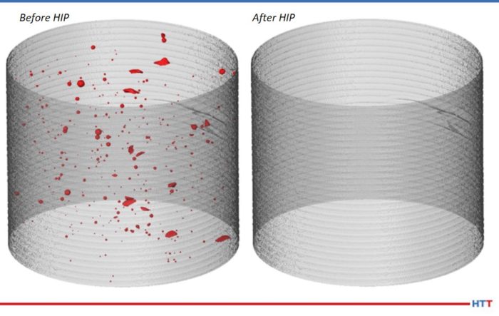
Figure 1. Defect elimination by HIP for E-PBF Ti-6Al-4V [8] (Photo source: Quintus Technologies)Hot isostatic pressing uses a high isostatic gas pressure, up to 207 MPa (30,000 psi), and elevated temperature, up to 3632°F (2000°C), to eliminate these internal defects and achieve a 100% dense material. The elimination of defects results in improved fatigue properties, ductility, and fracture toughness.1-7 For this reason, HIP is widely used for orthopaedic implants like hip, knee, spine, ankle, wrist as well as dental implants to ensure quality and performance and prevent early failure of the implant inside the patient. Common materials are cobalt-chrome alloys like ASTM F75, titanium alloy Ti-6AL-4V, and stainless steel 316L. The densification by HIP for additive manufactured (E-PBF) Ti-6Al-4V is shown in Figure 1 where a printed coupon has been analyzed with X-CT before and after HIP.
New Possibilities with Additive Manufacturing
Developments within additive manufacturing of metal parts have opened up possibilities for patient-specific orthopaedic implants where the implant is tailor-made based on X-ray imaging of the patient for a perfect fit. AM makes patient-specific implants economically viable since there is no tooling such as casting moulds or forging dies; therefore, it is easy to make new unique designs without adding significant cost and lead time to the production process.
Patient-specific implants offer many benefits to the patients and doctors, including better fit to the existing bone structures, shorter surgery times, faster recovery times, and less risk of implant loosening inside the patient.9 The demand for patient-matched implants produced by AM is growing steadily and is predicted to accelerate as production costs are coming down. A fundamental change with personalized implants is that there is no possibility for the healthcare system to stock implants since every implant is unique and made to order. This results in shorter lead times in getting the implant made, which is very important because that is also the wait time for the patient. Minimizing the lead time for the different steps in the manufacturing process, including HIP and heat treatment, is a huge driver.
Optimized HIP and Heat Treatment for AM
The nature of the additive manufacturing process is quite different from conventional casting and forging manufacturing resulting in different microstructures in the as-manufactured condition. For example, the solidification and cooling rates in powder bed fusion (PBF) are several thousand degrees per second, while the casting rate can be a few degrees per minute resulting in microstructural differences even for the same alloy. Despite the differences, most HIP and heat treatment protocols used for AM parts today are developed for cast and wrought material and might not be optimal for AM material. One reason is that these traditional standard HIP protocols are often the only option available in industry today, like at a HIP service provider.
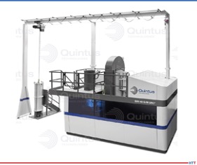
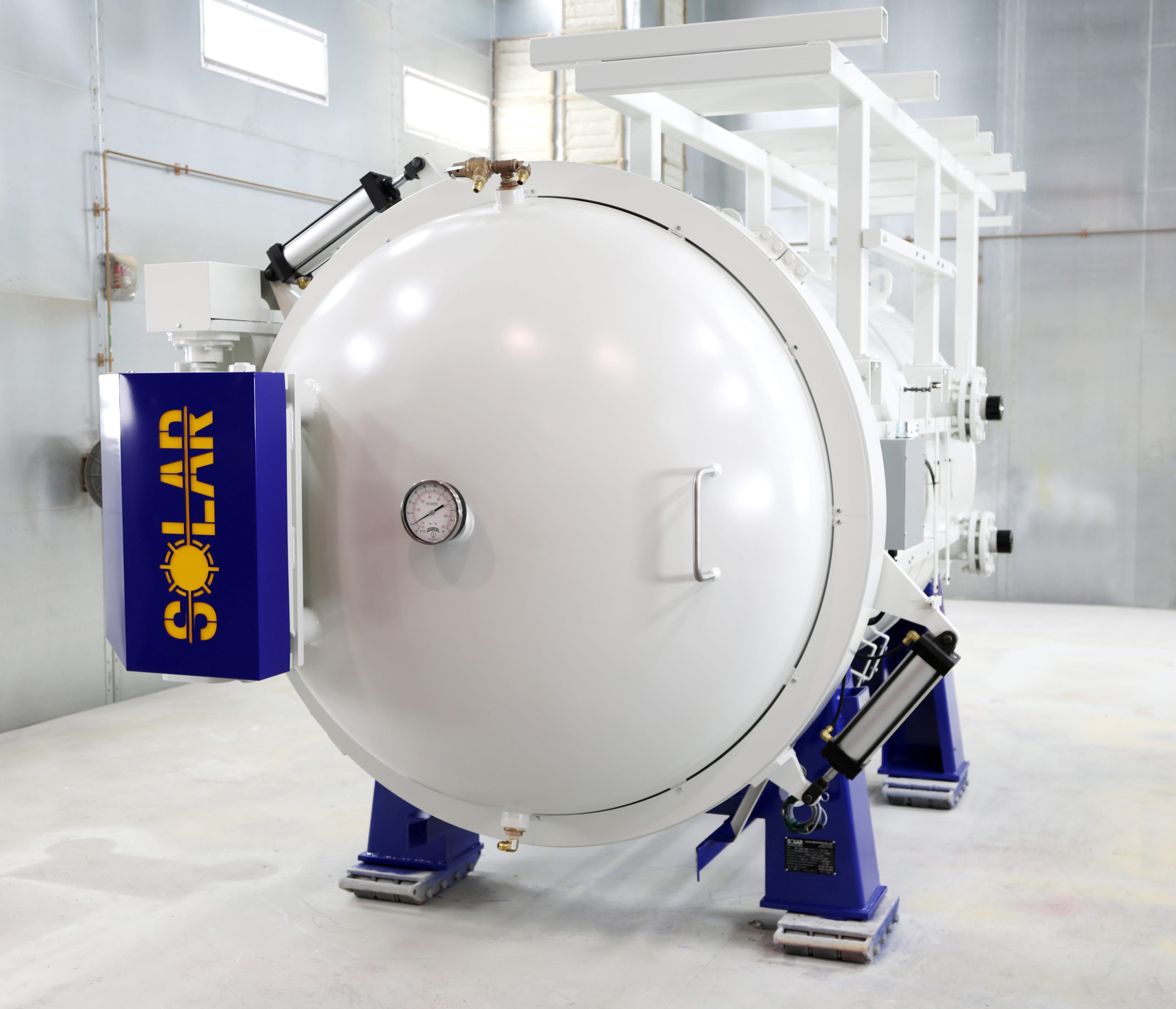
Figure 2. Quintus® QIH48 HIP system (Photo source: Quintus Technologies)
Studies have shown that there is potential to achieve significant improvements in material properties when optimizing the HIP process specifically to AM material. One example is presented in Optimizing HIP and Printing Parameters for EBM Ti-6Al-4V, HIP1710 where an optimized HIP cycle for E-PBF Ti-6Al-4V was investigated as an alternative to the traditional cycle used in industry today of 1688°F, 14.5 ksi (920°C, 100 MPa) and 2 hours soak time. In this study it was found that a modified HIP cycle with lower temperature and higher pressure gave significantly higher yield and tensile strength with retained ductility compared to the traditional HIP cycle. A similar study presented in Evaluation of HIP-Parameter Effects on AM Titanium Ti-6Al-4V 11 shows that that the modified HIP cycle with lower temperature and higher pressure also leads to improved fatigue properties compared to material treated with the traditional HIP cycle for L-PBF Ti-6Al-4V.
A New Era of HIP Equipment
A lot of developments and improvements have been made within equipment for hot isostatic pressing in recent years. A modern HIP system today is space and cost effective and easy to operate and maintain. Quintus Technologies offers HIP systems in a variety of different sizes suitable for a wide range of production volumes. Such product offerings enable the appropriate fit for many business cases.
One important innovation within HIP technology is the rapid cooling capability available in Quintus® HIP systems (Figure 2). The high cooling rates are achieved by a forced convection cooling of the highly pressurized argon gas in the HIP process with a maximum cooling rate up to 7200°F/min (4000°C/min).
Rapid cooling significantly shortens the HIP cycle time since the cooling segment of the cycle takes minutes instead of several hours as compared to a conventional HIP system. This makes the modern HIP system very productive with a lower initial capital expenditure because smaller HIP units can handle higher throughput.
Combining HIP and Heat Treatment
Fast cooling and quenching directly in the HIP system also make it possible to perform many conventional heat treatments for metals, allowing for integrated heat treatment with the HIP cycle.
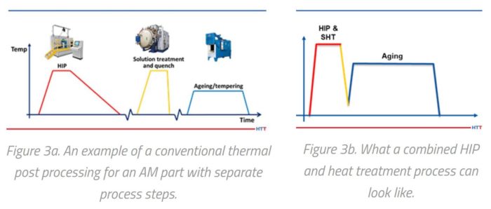
The main purpose in combining HIP and heat treatment is to eliminate process steps to achieve a shorter and more cost-effective post processing. In Figure 3a, a schematic visualization shows how conventional thermal post processing for a cast, AM or MIM implant, could look when the thermal treatments are performed separately. These steps are often performed in different equipment and sometimes even at different physical sites.
The possibility to do rapid cooling and quenching in the HIP system enables the combination of the HIP and solutionizing step to be performed at the same time in the HIP furnace. Other potential steps such as stress relief, aging, or tempering can also be incorporated into the HIP cycle. In Figure 3b, a potential combined post processing route is shown for the same case as shown in Figure 3a.
When more process steps can be included into the HIP cycle, the total processing and production lead time is reduced. The transfer operations between different steps, for example, from the HIP to a vacuum furnace, are also eliminated saving time and cost. Another benefit is that energy consumption can be reduced by running the combined process, since the parts don’t have to be heated up and cooled down as many times. When combining the HIP and solutionizing step, as seen in Figure 3b, the time at the elevated temperature for the implants can be significantly reduced; that means that potential grain growth during the post processing can be minimized, which is often desired.
HIP and Heat Treatment of CoCr ASTM F75
A good example for combined HIP and heat treatment is cobalt chrome alloy ASTM F75, which is a common material for orthopaedic implants. This material is prone to form carbides during the processing that have a detrimental effect on the mechanical properties.12 The standard HIP cycle for this material is 2192°F, 14.5 ksi (1200°C, 100 MPa) with 4 hours soak time, and at these conditions the carbides will dissolve. However, the carbides will form again during the cool down from the HIP temperature unless the cooling is done fast enough to prevent reprecipitation. The minimum cooling rate required to avoid precipitation of carbides during the cool down is around 360°F/min (200°C/min), according to standard ASTM F3301-18.
Since conventional HIP systems without rapid cooling capabilities will cool much slower than 360°F/min (200°C/min), the material will contain these detrimental carbides after HIP. To correct this, a homogenization or solution anneal treatment is added after the HIP step. Treatment parameters typically consist of a soak at 2192-2246°F (1200-1230°C) for 4 hours in a vacuum furnace where the minimum cooling rate can be achieved. Therefore, the parts are moved to a different type of furnace and heated up to the same temperature and soak time as the HIP process with the sole purpose to achieve a high enough cooling rate to obtain the desired microstructure and properties.
Thanks to the rapid cooling in a modern Quintus® HIP system, ASTM F75 components instead can be cooled directly in the HIP system at a high enough rate to avoid carbide formation and thereby completely eliminating the need for a separate homogenization/solution treatment. The result is that only one thermal treatment is needed instead of two, one piece of equipment needed instead of two, and the material will spend 4 hours at elevated temperature instead of 8 hours, which is beneficial. This is applicable on both cast and AM implants as well as MIM.
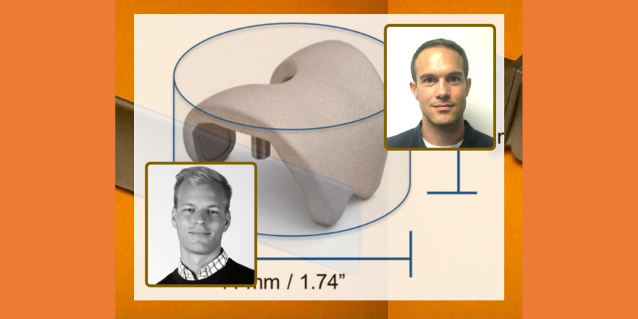
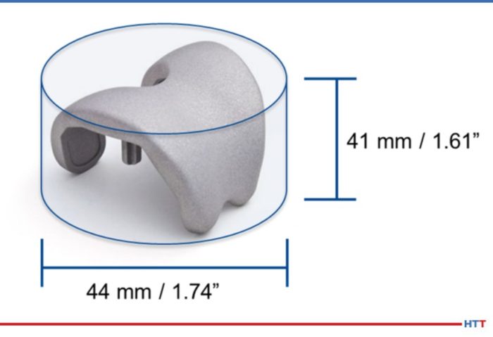
Figure 4. Size of femoral knee implant used for case study (Photo source: Quintus Technologies)
The Productivity of a Modern HIP System
The rapid cooling capability of these systems lead to a significant reduction in the HIP cycle time and thus, improved productivity of the production chain. To demonstrate the high capacity of these HIP systems, a production case is presented below where two Quintus® HIP systems, the QIH15L and the QIH48, have been compared.
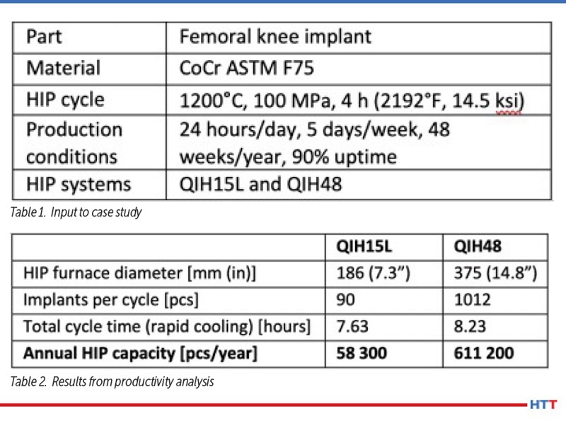
For this case study, a femoral knee implant made of ASTM F75 has been chosen. The size of the implant can be seen in Figure 4 represented by a cylinder. It is assumed that the implants are not allowed to be in contact with each other during the HIP cycle, so it calculates how many cylinders can fit in each furnace, making the calculation conservative. The HIP parameters for this case are 2192°F, 14.5 ksi (1200°C, 100 MPa) and 4 hours with rapid cooling, which will determine the HIP cycle time. The production conditions in this case are chosen to be 24 hours/day, 5 days/week and 48 weeks/year with a 90% uptime of the HIP system. All input data is summarized in Table 1 and the results are presented in Table 2.
As can be seen in Table 2, the QIH15L can process 58,300 implants per year while the QIH48 can produce 611,200 in the same time frame. These numbers are quite high considering these two HIP models belong to the Quintus® Compact HIP series and are relatively small units aimed at in-house production lines. The HIP cycle time is around 8 hours and the larger HIP system, the QIH48, has a slightly longer cycle time compared with the smaller QIH15L. This cycle time is calculated with the assumption that rapid cooling is used. If a conventional system without rapid cooling is used instead, the total HIP cycle time can be as much as twice as long, close to 16 hours total, showing the impact of the rapid cooling capability on system productivity. Of course, this would be reflected in half the number of parts per year. A more comprehensive productivity and cost analysis for modern HIP systems have been made in Cost-Effective Hot Isostatic Pressing – A Cost Calculation for MIM Parts.13
The Benefits of Insourcing the HIP Process
Traditionally, most orthopaedic implant manufacturers have been outsourcing the HIP process to external HIP service providers rather than having the HIP process in-house, and that is still the situation today. A benefit of using a HIP service provider is that it is a cost-effective alternative even for relatively small annual volumes. This is possible since the service provider can consolidate different lots from different customers together in one HIP cycle, so called coach cycle, making it a cost-effective route.
However, insourcing the HIP process is becoming more interesting and some implant manufacturers have already invested in HIP equipment to facilitate the HIP process in-house. One reason for this trend is the strong technical development of the modern-day HIP equipment, as already discussed in the previous chapter.
Insourcing the HIP process has several positive aspects and some are discussed here below:
Shorter production times – Since the time of transport to and from the service provider is eliminated along with the turnaround time at the service provider, the lead time for HIPing the implants can be significantly reduced. When HIP with in-HIP heat treatment capability is fully integrated into the production process, process steps can be eliminated and time waste can be minimized.
Eliminate risks – Since the transporting to and from a service provider is eliminated, so are the risks related to transport delays and damaged/lost goods.
Production flexibility – Full control over the production schedule and lead times result from the flexibility to run cycles when needed and possibly to fast-track time-critical deliveries through the internal schedule. This can be important for patient-specific devices where short lead time is always a requirement.
Control over quality and process improvement – With the full HIP and heat treatment process in-house, the quality system can be further developed to avoid mistakes and non-conformities, while good-receipt inspection can be minimized. Typical issues can include loss of implant traceability, parts being treated with the wrong HIP parameters, and surface contamination such as surface oxidation and alpha casing etc. Internal know-how and expertise on how to run the HIP process will be developed over time to avoid quality issues and delays, all with the help of the Quintus Care® program.
Optimized HIP and HT protocols – When operating the HIP process in-house, one is not limited to the standard coach cycle generally offered by the HIP service industry. Instead, the HIP process can be tailored for the needs and requirements of specific parts and materials made by casting, AM, or MIM to achieve maximum performance and quality of the implants. This possibility is extra important for parts produced by additive manufacturing (AM) since optimized HIP cycles, specifically for AM material, can result in significantly improved material properties compared to the standard HIP cycles as has been shown. Opportunities include integrating different heat treatments into the HIP cycle that are enabled by rapid and steered cooling to achieve the most effective production route, facilitating in-house R&D to continuously improve HIP processing, and optimizing for new products and applications. Today, there are HIP service providers on the market who have modern HIP systems with rapid cooling capabilities that can also offer optimized cycles and combined HIP and heat treatment.
Lower total production cost – Having a high utilization rate on an in-house HIP system yields the lowest operating cost for the HIP process. The cost for heat treatment can potentially be eliminated completely if the combined HIP and heat treatment approach can be used. Since transportation to external sub-contractors can be avoided, the cost of transportation is eliminated as well as the cost of insurance during transport. There are also potential indirect cost savings from improved quality control routines, more flexible planning, and shorter delivery times.
So, overall control of the process when operating in-house is one of the key benefits when coupled with better properties of the implants, short lead times and low cost for the process.
Conclusions
In this paper we have discussed the development of modern HIP technology such as the possibility to perform rapid and steered cooling directly in the HIP, which gives a significantly improved production capacity of the HIP system. The rapid cooling capability of modern Quintus® HIP systems also makes it possible to include heat treatment processes directly into the HIP cycle with the purpose of eliminating process steps for shorter lead times and more lean production.
AM is growing as a production method for orthopaedic implants with a potential for modifying and optimizing the HIP cycles for AM-produced components. Such optimized approaches offer a product with enhanced material properties compared to traditional HIP cycles, which were often developed for cast and wrought material.
The advantages of operating the HIP process in-house include minimal lead time, control over quality, process improvement, flexibility in production planning, the possibility to use optimized HIP cycles, and a lower total production cost from direct and indirect cost savings.
References
[1] JJ. Lewandowski and M. Seifi, Metal Additive Manufacturing: A Review of Mechanical Properties, Annual Review of Materials Research 46, pp. 151-186, 2016.
[2] J. Kunz et al., Influence of HIP Post-Treatment on the Fatigue Strength of 316L-Steel Produced by Selective Laser Melting (SLM), Proceedings WorldPM2016, Oct. 2016, Hamburg, Germany.
[3] S. Leuders et al., On the Fatigue Properties of Metals Manufactured by Selective Laser Melting: The Role of Ductility, J. Mater. Res. 29, 1911–1919, 2014.
[4] N. Hrabe et al., Fatigue Properties of a Titanium Alloy (Ti–6Al–4V) Fabricated Via Electron Beam Melting (EBM): Effects of Internal Defects and Residual Stress, International Journal of Fatigue vol. 94, pp. 202–210, Jan. 2017.
[5] J. Haan et al., Effect of Subsequent Hot Isostatic Pressing on Mechanical Properties of ASTM F75 Alloy Produced by Selective Laser Melting, Powder Metallurgy vol. 58 no. 3, pp. 161–165, 2015.
[6] V. Popov et al., Effect of Hot Isostatic Pressure Treatment on the Electron-Beam Melted Ti-6Al-4V Specimens, Procedia Manufacturing, vol. 21, pp. 125-132, 2018.
[7] R. Kaiser et al., Effects of Hot Isostatic Pressing and Heat Treatment on Cast Cobalt Alloy, Materials Science and Technology, Vol. 31, No. 11, Sept. 2015.
[8] S. Tammas-Williams et al., The Effectiveness of Hot Isostatic Pressing for Closing Porosity in Titanium Parts Manufactured by Selective Electron Beam Melting, Metall. Trans., Volume 47, Issue 5, pp 1939–1946, May 2016.
[10] M. Ahlfors et al., Optimizing HIP and Printing Parameters for EBM Ti-6Al-4V, HIP17 – 12th International Conference on Hot Isostatic Pressing, Dec. 2017, Sydney, Australia.
[11] T. Kosonen and K. Kakko, Evaluation of HIP-parameter Effects on AM Titanium Ti-6Al-4V, AeroMat19, May 2019, Reno, Nevada.
[12] M. Chauhan, Microstructural Characterization of Cobalt Chromium (ASTM F75) Cubes Produced by EBM Technique, Master Thesis at Chalmers University of Technology, 2017.
[13] M. Ahlfors et al, Cost-Effective Hot Isostatic Pressing – A Cost Calculation for MIM Parts, Metal Injection Molding International, Vol 12 No. 2, June 2018.
About the Authors:
Magnus Ahlfors works as application engineer in hot isostatic pressing where he is heavily involved in the development and optimization of HIP processes for different industries, especially for metal additive manufacturing. Magnus has a MSc in Materials Engineering from Chalmers University of Technology, Sweden and has worked at Quintus Technologies since 2013.
Chad Beamer has a MS from the Ohio State University in Material Science and has worked as a material application engineer with GE Aviation years and as a technical services manager with Bodycote. In February, Chad began working with Quintus Technologies as an applications engineer for the Advanced Material Densification division focusing on hot isostatic pressing (HIP). As an applications engineer, he manages the HIP Application Center located in Columbus, Ohio, educates on the advancements of HIP technologies, and is involved in collaborative development efforts both within academia and industry.
Heat treater ALP Aviation is increasing its production capacity and expanding process capability with a vacuum furnace. The furnace is dedicated to low pressure carburizing of transmission components for helicopters and other aircraft.
Sławomir Woźniak CEO SECO/WARWICK Source: secowarwick.com
The new vacuum furnace is configured with horizontal charge loading, a maximum cooling gas pressure of 15 bar of argon and nitrogen, and a 900mm x 900mm x 1200mm (W x H x L) charge area.
This Vector vacuum furnace is the heat treater's 4th installation in a 13-year cooperation with SECO/WARWICK, the parent company of North American-based SECO/VACUUM. "Our 13-year relationship with ALP AVIATION continues to be of mutual benefit on all technical and managerial levels," says Sławomir Woźniak, CEO of SECO/WARWICK Group. "[We provide] the technology, equipment and process knowledge which has enabled our client to grow their business. Our Group values working close to the customer."
Heat treaters across North America in Georgia, North Carolina, and Ontario have requested that heat treat furnaces be used in the production of powertrain, suspension, and steering/linkage components for the automotive sector. The demand for new furnace equipment has been driven by both light weighting initiatives and a shortage of in-house heat treatment capacity.
Cast Link Belt Press source: CAN-ENG Furnaces Ltd.
CAN-ENG Furnaces International Ltd., a global furnace systems group based in Canada, has been contracted by multiple unique customers in the United States and Canada to deliver these different furnaces for the heating and heat treatment of both aluminum and steel closed die forgings. The furnace configurations -- either under construction in the company shops or in the early stages of commissioning -- include rotary hearth, chain conveyor, roller hearth, mesh belt and cast link belt.
All contracts will be in production by late Q1 2021.
A captive heat treater in New England will receive a 10-bar gas quenching vacuum furnace. The model features high pressure gas quenching and vacuum carburizing. With temperature uniformity of ±10°F, it is consistent with AMS2750F requirements.
Jason Davidson Northeast Regional Sales Manager Solar Source: solarmfg.com
"The research and development done with our sister company, Solar Atmospheres, on the alloy selection, carburizing, and recipe process development, was instrumental to the sale of the furnace," states Jason Davidson, Northeast regional sales manager at Solar. He adds that the customer valued the additional resource that the sister company had to offer.
The furnace has a graphite insulated hot zone with a work area measuring 24” wide x 24” high x 36” deep and a load weight capacity up to 2,000 pounds. Its maximum operating temperature of 2400°F.
You can see these dimensions in the video below that the supplier, Solar Manufacturing, shared on Twitter.
Solar Manufacturing recently shipped a 10-bar gas quenching vacuum furnace to a captive heat treater in New England.
Global commercial heat treater HTA Group (HTA) ordered a vacuum aluminum brazing furnace. It will operate within a tight temperature tolerance of +/- 3° C, as dictated by AMS2750F, allowing HTA to continue to provide accredited heat treatment processing services to the global aerospace industry.
With three locations in Australia and one in the United States, HTA will be using this furnace to braze aluminum parts for applications where the use of brazing flux is not permitted due to corrosion. This is the seventh furnace -- and the 3rd vacuum brazing furnace -- that SECO/WARWICK will be providing to HTA.
"Our team of experienced heat treatment professionals appreciate working with SECO/WARWICK experts and technologies," said Norm Tucker, director at HTA Group. "We demand high quality, precision solutions due to the stringent requirements of the aerospace applications that we work with."
The vacuum aluminum brazing system has been designed with 6 temperature control zones in order to meet the temperature requirements of +/- 3° C as specified by the AMS2750F pyrometry specification. Additionally, the furnace provides the deep vacuum and perfect temperature uniformity to meet the Class 1 requirements of the pyrometry specification. The powerful high vacuum system will be equipped with a large diffusion pump and built to accommodate loads up to 800 x 800 x 1600mm (W x H x D). The furnace will be equipped with an external gas cooling system, which will both accelerate the process and improve the part quality after brazing.




 Medical devices, medical tools, and prosthetics all have a long history with heat treating. As we look to the future, the materials industry and the advancement of AM into the heat treat industry is moving at lightning speed.