Intelligent Cooling System Improves Operations for Alloy Manufacturer: A Case Study

There’s only one constant about technology. It’s always evolving—revealing new innovations and opportunities. And as these new technologies come to light, heat treating operations have new opportunities to reduce cost, increase efficiency, and ensure consistent, optimized part quality, regardless of the job parameters. With the introduction of new process cooling technologies to the heat-treating market, previously unexplored systems become viable solutions for unanswered operating challenges.
When a tempered alloy manufacturer faced strict job requirements that demanded capabilities outside the competences of traditional technologies, a modular process cooling systems designer and manufacturer based in Italy with a North American operation located in East Dundee, Illinois, proposed a process cooling system that addressed key problem areas, while ensuring top system performance. As a result, the company was able to document operational cost savings of over $80,000 per year.
Gary Burdardt, market development manager with Frigel North America, is the author of this case study.
The Need for a Better Cooling Solution
Located on the East Coast, the manufacturer needed to find an alternative process cooling solution for its vacuum furnace cooling operation. It had been using air-cooled chillers, but the costs of continuous operation were too high. Operating as a batch furnace, the heat load of this particular application was specified to be approximately 200 tons, and process cooling water temperature, which was specified at 70°F, presented a significant challenge.
At 70°F, the required temperature was much lower than typical process cooling temperatures. For many vacuum furnace cooling processes, water temperatures can be specified as warm as 100°F for successful heat extraction. Because furnace vessels and resulting materials can reach temperatures as high as 1,300 to 1,700°F, water temperatures of at or near 100°F are able to maintain furnace vessel inner wall temperatures below a maximum (safe) temperature of 300°F. Though the final part temperature can be inconsequential, the batch of product needs to be cooled enough for comfortable handling in downstream operations.
Traditional technologies are capable of maintaining 100°F cooling water year-round. Maintaining temperatures consistently at 70°F is much more difficult. Facing high costs and strict temperature requirements, the manufacturer needed a new process cooling approach.
In this application, the manufacturer identified several process cooling areas of concern that, left unsolved, could jeopardize operations.
First and foremost, process cooling systems needed to adequately reduce heat transmission from the furnace vessel to the ambient environment. In addition, the air-to-water heat exchanger, used for batch cooling inside the chamber, needed to be cooled after the tempering process was complete. Likewise, the diffusion pump, used to evacuate air from the vacuum chamber, as well as the electrical cabinet relied on process cooling for optimized function. If the diffusion pump failed to perform as expected, part quality would be jeopardized, leading to potential contamination and material inconsistencies, and reducing the value of the final product.
Traditional Technology Limitations Explored
Initial investigations into solutions revealed apparent limitations. Traditional process cooling methods were unable to cost-effectively maintain water-cooling temperatures of 70°F. This made finding an alternative solution critical. Three traditional methods were explored:
Evaporative cooling towers
This technology is incapable of achieving consistent temperatures in the 70°F range. Cooling water temperatures are controlled by the wet-bulb temperature, relying on evaporation in ambient air conditions. As a result, they can often only provide 85°F or higher water temperatures to processes year-round. This cooling technology tends to be maintenance-intensive given the reliance on chemical treatment and filtration to maintain water quality. Additionally, evaporative towers consume excessive amounts of water.
Dry fluid coolers
This technology would only be effective in this application when air temperatures were at 55°F or below. Though reducing the need for chemical treatments and eliminating excessive water consumption, this system can only produce water that is typically 10-15 degrees warmer than the dry-bulb temperature, or the ambient air temperature without moisture. As a result, temperature tolerance would be lost during the warmer months. During the colder months, the use of glycol antifreeze solutions is necessary to maintain system functionality, which in many cases requires the use of additional pumping systems and water-to-glycol heat exchangers.
Central chillers
The conventional approach relies on a chilled water system that incorporates chillers to generate 70°F temperatures. This system can be supplemented with a dry fluid cooler if conditions for free cooling were significant enough for payback in three years or less. In many cases, the cold, consistent temperature of the water produced by the chillers is cooler than is necessary for most heat-treating components, leading to increased energy inefficiencies and accrued higher costs.
Faced with the limitations of traditional technologies, the manufacturer turned to an alternative process cooling system for the answer.
Considering an Alternative System
Once traditional methods were thoroughly analyzed, the choice was easy. Providing an alternative solution, the Frigel system design was selected and implemented into the vacuum furnace cooling application.
Frigel’s Intelligent Process Cooling systems are designed to create better processes for heat treating operations and provide a unique, flexible solution. The solution combines the use of its internationally patented closed-loop adiabatic fluid cooler with small, dedicated chillers to maximize opportunities for free cooling while ensuring consistent and reliable process cooling temperatures. The closed-loop adiabatic fluid cooler operates outside of the facility, with chillers located near each work cell or process. This approach allows for greater flexibility as individual process cooling needs change.
As a closed-loop system, it requires fewer resources and creates additional opportunities for free cooling capabilities. Water consumption is greatly reduced as opportunities for evaporation are removed. Water consumption is lowered by as much as 95% when compared to an evaporative cooling tower. The closed-loop system also prevents process cooling water from being exposed to the outside air, reducing the need for chemical treatments and additional filtration efforts.
When compared to an evaporative cooling tower, chemical use can be reduced by as much as 40%, appealing to strict municipal water quality regulations while improving system reliability and uptime. Maintenance issues are also drastically reduced in comparison to open-loop systems. Contamination, corrosion, and deposits are all threats to machine performance. By reducing opportunities for cooling coils to interact with moisture, and cooling water exposure to the open air, maintenance-intensive issues are lessened. As a result, production uptime is optimized.
The closed loop-adiabatic cooler system also allows for greater free-cooling opportunities. When ambient conditions are appropriate, localized chillers are bypassed. Instead, heat is transferred to the air via copper tubes in the adiabatic chamber of the fluid cooler, and the cooled water is returned to the furnace vessel. Meanwhile, localized chiller compressors are automatically shut down, saving energy and reducing costs. Working together, the closed-loop adiabatic cooler system and localized chillers are able to provide cooling water temperatures at a wider range of ambient conditions, allowing greater flexibility throughout the heat-treating process.
Additionally, an Intelligent Process Cooling system provides a modular solution. With the fluctuation of job demands and shifting job requirements, the system can expand to fit each unique process cooling need. The use of dedicated chillers allows work cells to be self-contained, reducing disruption and downtime as new process cooling requirements adapt and develop with business growth.
Applying the Intelligent Process Cooling System
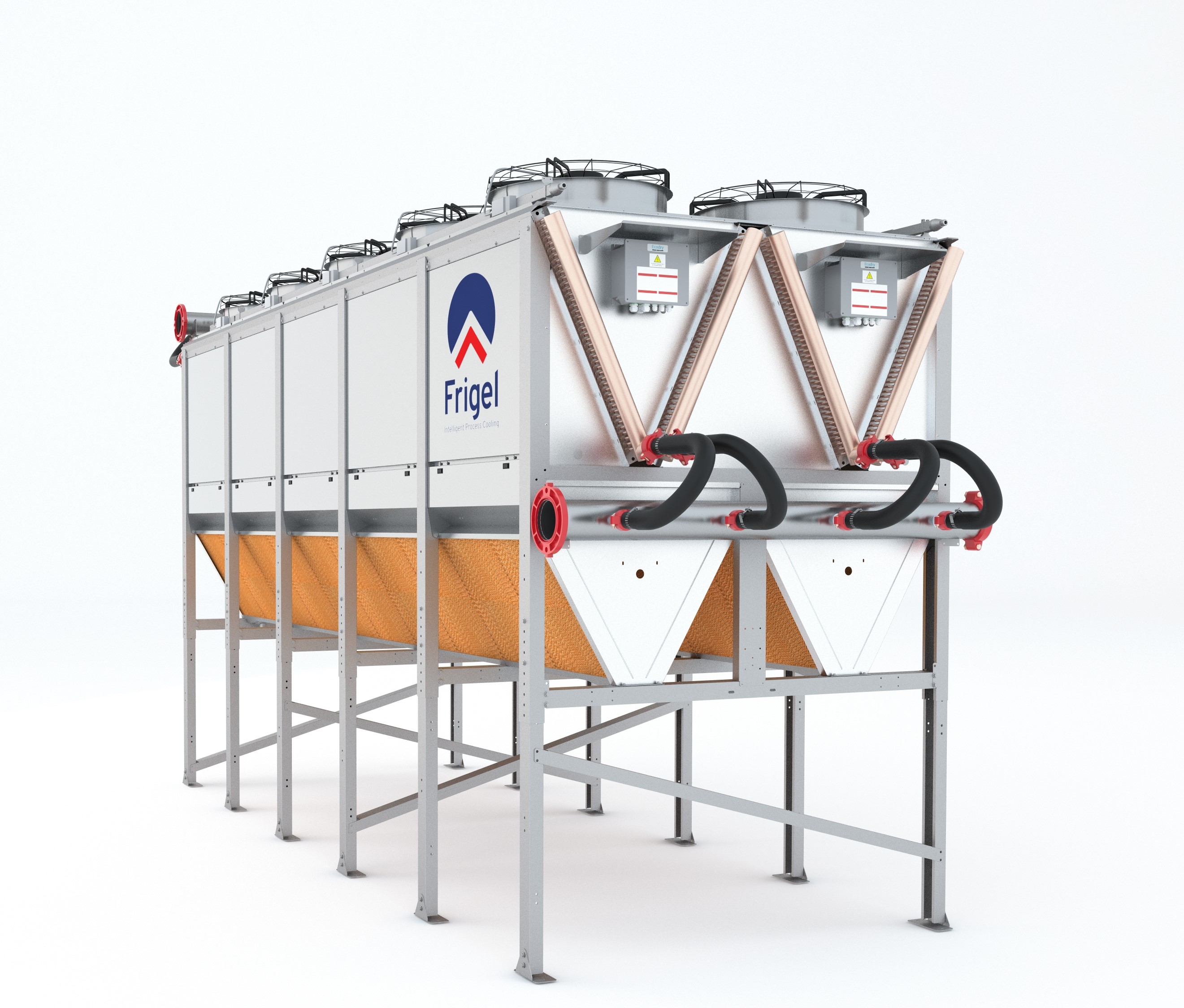
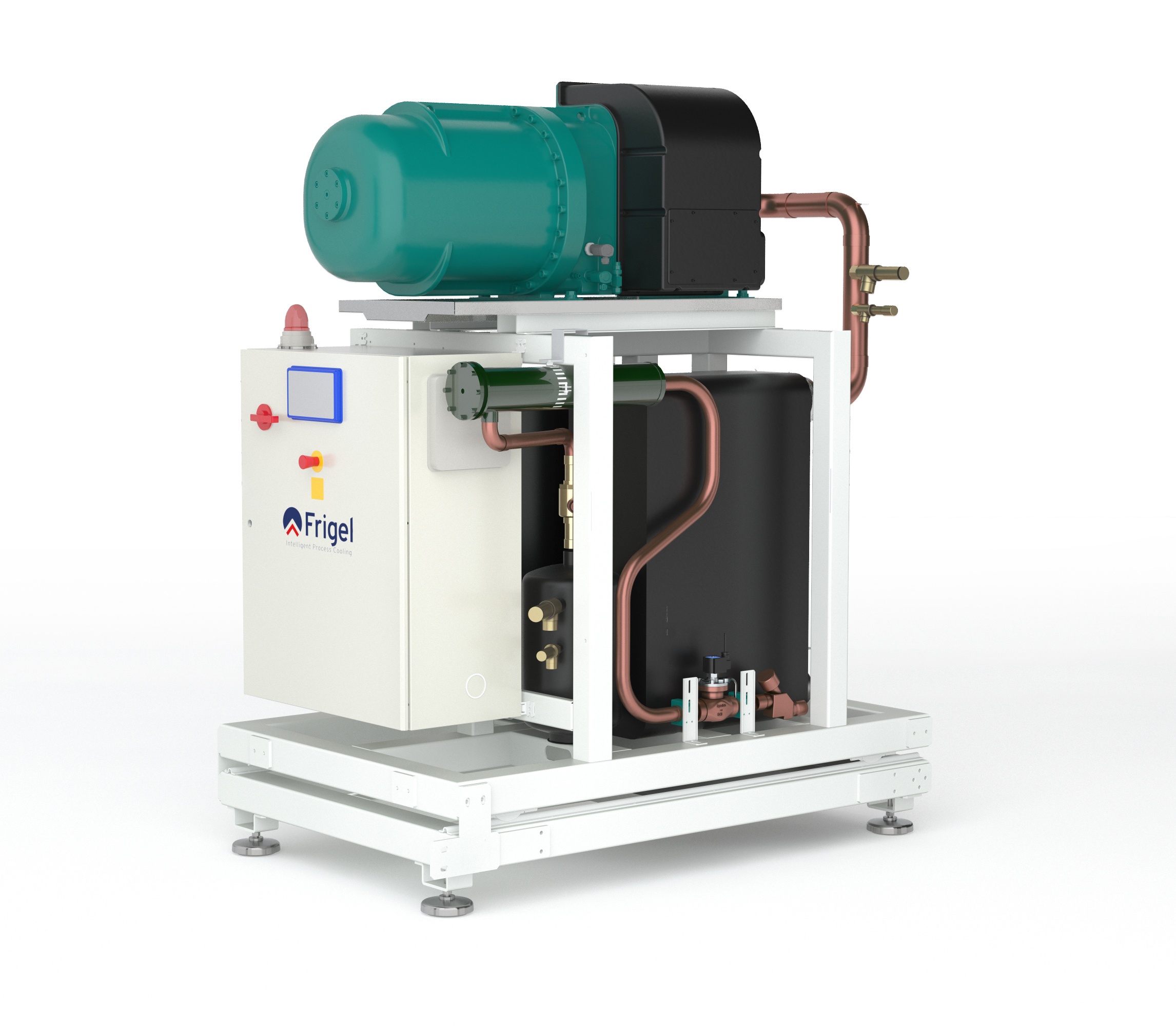
At the alloy manufacturer, the Intelligent Process Cooling system installed includes an Ecodry fluid cooler with a patented adiabatic chamber and several water-cooled chillers.
Throughout the year, this system leverages free cooling when ambient conditions permit (see Figure 1). For this manufacturer, the installation location provides ambient temperatures that are quite mild, reducing the necessity for localized chillers from approximately the beginning of October to the end of April. Instead, process cooling water transfers heat to the ambient air via the copper tube and aluminum coils in the adiabatic fluid cooler. Once cooled, water travels to the pump skid, then returns to the furnace vessel where it cools the furnace jacket, furnace door, diffusion pump, and heat exchanger.
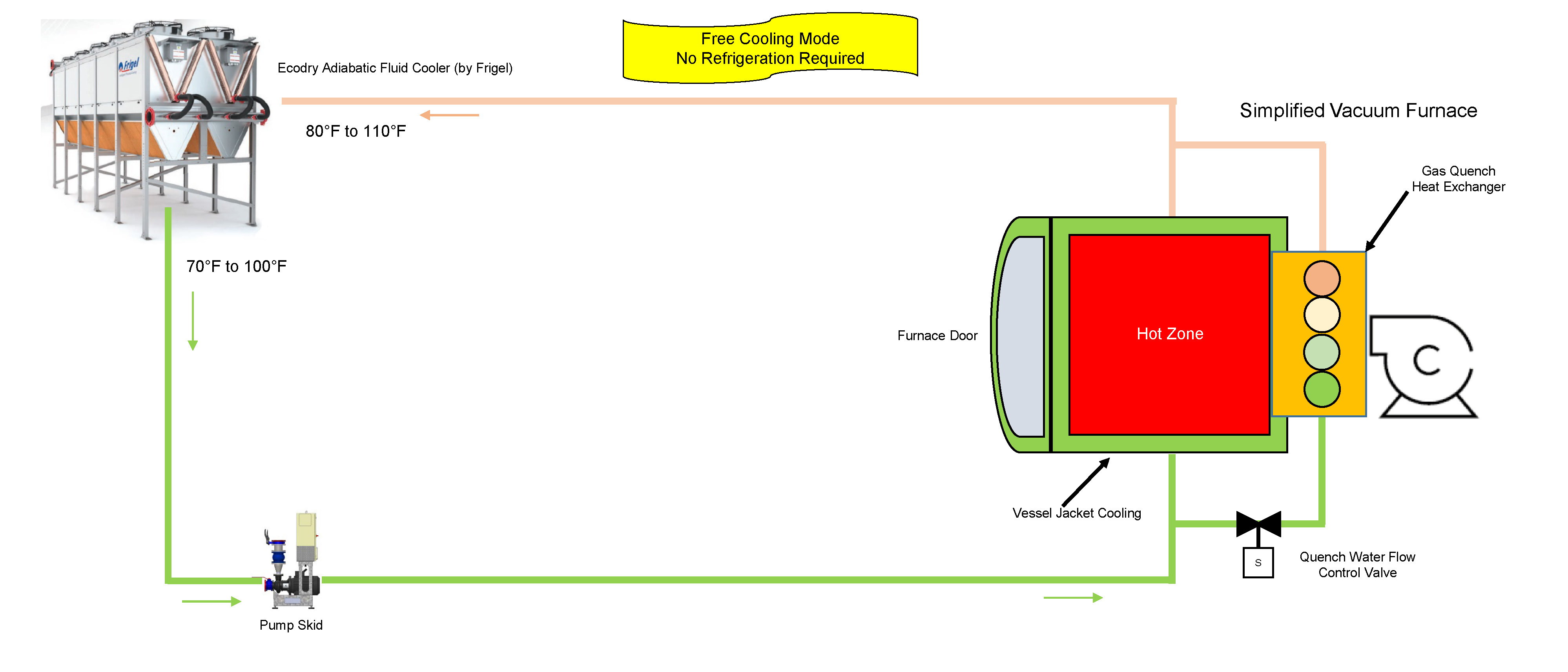
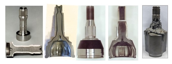
While the furnace is in processing mode, process cooling water runs between the shells of the vacuum, cooling the inner walls, furnace jacket, furnace door, and diffusion pump. This ensures the furnace exterior maintains a safe temperature and the diffusion pump is able to sustain necessary atmospheric pressure within the furnace vessel. Following the completion of the processing cycle, the quench water flow control valve sends process cooling water to the heat exchanger, decreasing furnace vessel temperatures to the desired temperature for part handling and extraction.
Existing water-cooled chillers supplement the cooling process during the rest of the year when set temperatures can no longer be maintained with the use of free cooling (see Figure 2). When temperatures are at their highest, the water-cooled chillers generate the 70°F coolant and the heat is transferred to the Ecodry loop via the chiller condensers. From there, the chilled water travels to the furnace vessel, cooling the furnace components. Once the water has passed through the process, it returns to the adiabatic fluid cooler, and the water-cooling process begins once again.
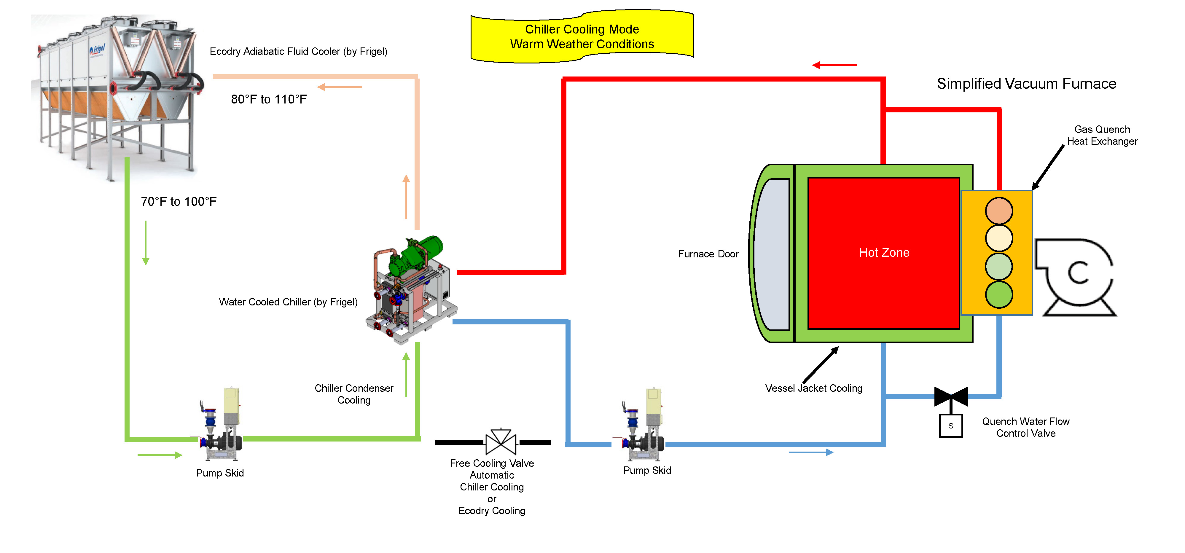
If and when ambient temperatures exceed 85°F, the adiabatic chamber of the fluid cooler initiates the spray system to lower incoming air temperatures closer to the wet-bulb temperature. By doing so, the coolant is lowered to a temperature that maintains reliable, efficient operations.
Operational Savings of $80,000 Per Year and More
By leveraging a closed-loop system with an adiabatic chamber, the alloy manufacturer achieved benefits that weren’t possible with traditional technologies. Chiller run time is in the 1,500 hour-per-year range and adiabatic cooling is required less than 400 hours per year. Compared to an evaporative cooling tower and water-cooled chiller system, water use has been reduced by 95% and electrical energy costs have been reduced by 60%. Increased efficiencies and reduced water consumption have resulted in operating costs that are dramatically less than any other system. In total, the plant saves over $80,000 per year with the Frigel system.
For this manufacturer, an alternative solution to traditional process cooling technologies was the only viable option. High costs drove innovation and a need for a better approach. Frigel’s Intelligent Process Cooling system, leveraging the capabilities of a closed-loop adiabatic system and localized water-cooled chillers, allowed for greater operational flexibility while reducing costs and maximizing efficiency—providing the manufacturer with a better process cooling solution.
About the Author
Gary Burgardt, Frigel North America’s market development manager, works closely with prospects and customers to ensure every Frigel process cooling solution delivers measurable results based on each company’s unique processes and business goals. In addition to expertise in Intelligent Process Cooling, Burgardt leverages 30 years of experience in process cooling across a wide range of industries to assist customers at every stage of the planning and buying process.
For more information, visit www.frigel.com.
Intelligent Cooling System Improves Operations for Alloy Manufacturer: A Case Study Read More »


![Figure 2. Computer-modeled EMF distribution in the transverse cross-section of a bare inductor (left) compared to an inductor with U-shaped flux concentrator (right). Note: the scale of magnetic field intensity on both images is different [1].](https://heattreattoday.com/wp-content/uploads/2019/08/Rudnev-Part-2-Fig-2.jpg)
![Figure 3. Sketch of single-shot induction hardening of an axle shaft. Note: The right half of this induction system is computer-modeled in Fig. 4 [3].](https://heattreattoday.com/wp-content/uploads/2019/08/Rudnev-Part-2-Fig-3.jpg)
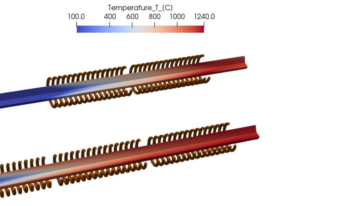
![Figure 4. Results of numerical simulation of heating an axle shaft by using a single-shot inductor [3].](https://heattreattoday.com/wp-content/uploads/2019/08/Rudnev-Part-2-Fig-4.jpg)