AMS2750F – Changes and Implementation
![]() AMS2750F? What are the new changes? How do you implement them? This informative article from Heat Treat Today's Aerospace 2021 issue will help you navigate through the uncertainty of these changes to ensure successful compliance.
AMS2750F? What are the new changes? How do you implement them? This informative article from Heat Treat Today's Aerospace 2021 issue will help you navigate through the uncertainty of these changes to ensure successful compliance.
This Technical Tuesday is an original content contribution from Jason Schulze, the director of technical services at Conrad Kacsik Instrument Systems, Inc. Check out other technical articles here.

Director of Technical
Services
Conrad Kacsik Instrument
Systems, Inc.
Introduction
AMS2750F has been released for approximately 7 months now. This specification applies to manufacturers and suppliers who heat treat aerospace material. AMS2750F is typically communicated via industry standards such as SAE/AMS specifications as well as customer purchase orders and part prints. This specification gets even more complex when you apply Nadcap heat treat accreditation to the equation as Nadcap has a checklist dedicated to AMS2750, which, as of January 2021, has yet to be released.
In this article we will examine some of the changes within AMS2750F as well as discuss the implementation process for suppliers.
AMS2750F Changes
General Changes
AMS2750F now has 25 tables, where there were previously 11. These tables are no longer at the end of the specification (like most SAE/AMS specifications); they are now placed throughout the specification adjacent to paragraphs to which the rewrite team thought they applied. The challenge with this is that all aspects of AMS2750 are interconnected. For example, one change in the qualified operating range of a furnace will directly affect other areas, such as instrument calibration and the temperature at which an SAT is performed.
Previously, temperature values were expressed in whole numbers. They are now expressed to the tenth of a degree (X.X°F). With this change, I would recommend suppliers follow suit in their own pyrometry procedures and associated documents: think of it as comparing apples to apples.
Scope and Definitions
The definitions section is important, especially to those who are new to AMS2750F who may be working to interpret some of the verbiage within the specification. The specification has increased the number of definitions from 79 to 87. A good example of these definition changes is the comparison of expendable thermocouples versus nonexpendable thermocouples.
- EXPENDABLE SENSOR: Sensors where any portion of the thermal elements are exposed to the thermal process equipment environment.
- NONEXPENDABLE SENSOR: Sensors having no portion of the thermal elements exposed to the thermal process equipment environment.
This example is especially important because it is such a major change from the previous revision of AMS2750. The definitions section within AMS2750F should be utilized often by suppliers to ensure comprehension and conformance.
Thermocouples
As simple as thermocouple technology is, there are many requirements within AMS2750F governing thermocouple usage, error, replacement, etc. Previously, AMS2750 did not address resistance temperature devices (RTDs). It now requires RTDs be nonexpendable, noble metal, and ASTM E1137 or IEC60751 (Grade A).
I do not see this next change as anything major, because what I’m witnessing in my consulting all around the US and Mexico are that suppliers already conform. Thermocouple hot junctions (the tips of the thermocouple measuring temperature) are made by either twisting, welding, or a combination of both.
In my experience, it is rare to see a thermocouple supplier/manufacturer issue a thermocouple certification that is nonconforming. Whenever there are issues with thermocouples, it is typically because the supplier did not communicate the correct information. With that, thermocouple error should be considered and communicated correctly.
Thermocouple permitted error has changed to the following:
- Type R & S: ±1.0°F or ±0.1%
- Type B: ±1.0°F or ±0.25%
- Base metal: ±2.0°F or ±0.4%
- AMS2750E permitted ±4.0°F or 0.75% for TUS, load and furnace thermocouples.
Exceptions:
- Note 11: For temperatures <32°F or <0°C for Types E and T only, calibration accuracy shall meet the following:
- Type E: -328 to 32°F, ±3.0°F or ±1.0 % for either, whichever is greater
- Type T: -328 to 32°F, ±1.8°F or ±1.5 % for either, whichever is greater
- Note 13: When correction factors are used, type B load sensors shall meet calibration accuracy of ±2.7°F or ±0.5% and types R and S load sensors shall meet calibration accuracy of ±2.7°F or ±0.25%
AMS2750 has always required that the results of an SAT and TUS must reflect corrected temperatures. This would mean when expressing the final ± readings of a TUS, those readings must be identified as corrected values. The challenge may come when you need a correction factor from a thermocouple certification where there is not a temperature value for the test. AMS2750F now addresses this situation:
- PARA 3.1.4.8 - Interpolation of correction factors between two known calibration points is permitted using the linear method.
- PARA 3.1.4.9 - Alternatively, the correction factor of the nearest calibration point shall be used.
- PARA 3.1.4.10 - Whichever method is used shall be defined and applied consistently.
Each supplier must decide what method they will utilize and document this. Know your customer requirements; some customers may not permit certain methods.
Sensor usage has changed dramatically, especially for expendable test sensors. These thermocouples are now limited to a single use above 1200°F regardless of the type. Between 500°F and 1200°F, Type K may be used five times or three months, whichever occurs first and for Type N, 10 times or three months, whichever comes first. Below 500°F, Type K may be used for three months with no limit to the number of uses, and Type N may be used for six months, with no limit to the number of uses. I can understand how this may seem like a lot to understand and filter through, but I can assure you, we will get used to it as we did with AMS2750E.
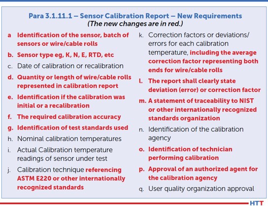
Thermocouple certification requirements have also changed. I do not foresee any issue with this as what is listed is, for the most part, already on existing thermocouple certifications. I would advise suppliers to check the requirement in bullet point “E.” (Figure 1)
Instrumentation
There were several major changes within the instrumentation section. The first one is readability of furnace recording and field test instruments. Previously, readability for all furnace and field test instruments was 1.0°F; it is now 0.1°F, or to the tenth of a degree. Suppliers may find this challenging to meet as not all field test instruments on the market are capable of this. An easy way to test yours is to either source or read the value on your field test instrument at 999°F. Then, increase the temperature to 1000°F.
On some units, when a temperature is reading/sourced below 1000°F, it will show to the tenth of a degree, but when increased above a tenth of a degree, the value in the tenths place will be removed and only whole numbers will be shown. If this is the case, you will need to purchase a new field test instrument which displays values to the tenth of a degree regardless of whether values go above 1000°F.
The second major change is timers or digital clocks on recording devices. This change makes sense, as most thermal cycles used to achieve metallurgical transformation are time-dependent and have specific tolerances that apply. AMS2750F now requires that these timing devices must be accurate to within ±1 minute per hour. There is a caveat which states that as an alternative, suppliers may have a synchronized system linked to NIST via internet system which is verified monthly and will support the ±1 minute per hour requirement. With that, a new paragraph, regarding stopwatch calibration and accuracy requirements, has been inserted adjacent to the recording device timing calibration requirements.
The third change, simple and straight forward, is that the instrument number or furnace number must be stated on the calibration sticker.
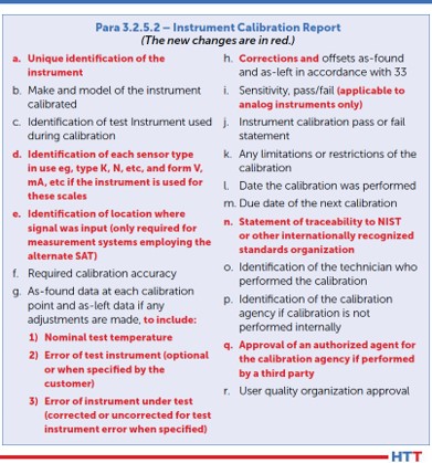
Additionally, changes have been made to what is required on an instrument calibration report. (Figure 2)
System Accuracy Testing (SAT)
There are several changes within the SAT section that should get attention. One which may continue to be overlooked is whenever an SAT cannot be performed (not that one fails), but if no product was run and the furnace was locked out, the SAT could be performed with the first production run (AMS2750E, para 3.4.2.4). This is no longer an option. AMS2750F now states that, in this situation, the SAT must be performed prior to putting the furnace back into service (or prior to production).
Furnaces that have multiple qualified operating ranges (i.e., CL2 from 1000°F to 1600°F and CL5 from 1601°F to 2000°F) must have the SAT performed in each range, at least annually. This means that if you typically run production at 1550°F and SATs are run at the same time, at least annually, an SAT must be processed above 1600°F to catch the CL5 range.
The alternate SAT process was the source of much confusion when revision E was released. Previously, single use thermocouples (i.e., load thermocouples) did not require an SAT per AMS2750D, para 3.4.1.2. When AMS2750E introduced the alternate SAT, the wording was so poor it caused suppliers to misunderstand the requirement, and subsequent audits yielded quite a few related findings. I have written previous articles explaining the alternate SAT process in detail, so I will not be going into this topic too deeply. For information, please visit www.heattreattoday.com and search Jason Schulze.
The changes within the alternate SAT section primarily amount to clarification and incorporation of what was previously in Nadcap’s pyrometry reference guide. That being said, there really isn’t much to speak of in this section for existing Nadcap suppliers, but one item to point out is how the wording has changed. Previously, it applied to single use sensors or sensors which were replaced more frequently than the SAT frequency requirement. This has been changed to state that the alternate SAT applies to load sensors used only once. Nadcap heat treat auditor advisory HT-20-010 has clarified this further. If load sensors are used more than once, the alternate SAT does not apply, and the comparison SAT must be used.
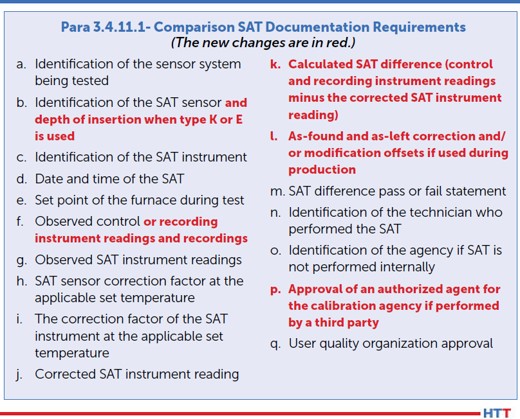
There were some minor changes to what is required on the comparison SAT report. (Figure 3)
Documentation related to the alternate SAT as well as the SAT waiver have been introduced. These should be examined closely by those suppliers to whom it may apply.
Temperature Uniformity Surveys (TUS)
Among many of the changes in this section, there is one that is not stated outright but is based on verbiage changes within Tables 18 and 19 of revision F regarding frequency. In AMS2750E, Tables 8 and 9, the statement reads “Initial TUS Interval” and “Extended Periodic TUS Interval.” Due to the wording, it was assumed that if four passing consecutive TUSs were needed before going to a reduced frequency, the initial TUS would count as part of the four needed. The modified wording in Tables 18 and 19 of AMS2750F now reads “Normal Periodic Test Interval” and “Extended Periodic Test Interval.” With this change in verbiage, the initial TUS does not count toward the needed consecutive tests to reduce TUS frequencies.
If a supplier uses vacuum furnaces for thermal processes and both partial pressure and low vacuum is used, a TUS must be performed annually in the partial pressure range using the gas applied during production. This is a rather simple change, although it is important to recognize that partial pressure gases, depending on certain variables, can affect the uniformity in the area in which the gas enters the furnace.
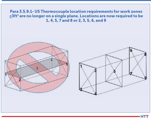
Thermocouple location for work zone volumes less than three cubic feet has changed. AMS2750E/Nadcap previously required that the five TUS thermocouples be placed on a single plane. AMS2750F has revised this to require each test thermocouple be placed diagonally opposite of each other. Using Figure 4, this could mean suppliers may choose locations 1, 4, 5, 7, and 8 or 2, 3, 5, 6, and 9.
Suppliers familiar with GE’s P10TF3 specification will recognize this next change as it was a GE requirement long before SAE/AMS introduced it into AMS2750F. Previously, data collection during TUSs needed to start prior to the first furnace or test thermocouple reaches the lower end of the tolerance (AMS2750E, para 3.5.13.3.1). This has changed and now requires data collection to begin when the furnace and TUS thermocouples are no fewer than 100°F below the survey temperature.
The documentation or TUS certification requirements have also changed. Considering that there are so many changes within this section, I will merely point out the letter annotations that apply to changes within Para 3.5.16.1: B, D, F, G, H, J, L, O, R, S, and Y. Some of these items contain simple verbiage changes, although most of them are solid changes and should be incorporated into suppliers’ procedures and forms.
Rounding Requirements
Previously, AMS2750E permitted rounding in accordance with ASTM E29. To the delight of many users, I am sure, this has changed. AMS2750F now permits rounding in accordance with the following options:
- All rounding must be applied in accordance with a documented procedure and used in a consistent manner.
- Rounding to the number of significant digits imposed by the requirement is permitted in accordance with ASTM E29 using the absolute method or other equivalent international standards. (Previously, the only method permitted was the rounding method.)
- The rounding method built into commercial spreadsheet programs is also acceptable.
- All specified limits in this specification are absolute and out of tolerance test data cannot be rounded into tolerance.
- Rounding must only be applied to the final calibration or test result.
Quality Provisions
The only change in this section is in regard to pyrometry service providers. The requirement now states, “Beginning 2 years after the release of this specification, third-party pyrometry service provider companies shall have a quality system accredited to ISO/IEC 17025 from an ILAC (International Laboratory Accreditation Cooperation) recognized regional cooperation body. The scope of accreditation shall include the laboratory standards and/or field service as applicable.” It is important to keep in mind that, when verifying conformance to this, the supplier’s scope of accreditation should include reference to AMS2750 with regards to instrument calibration, SAT, or TUS or all three if that is what is performed at your facility by an outside service provider.
Implementation of AMS2750F
he implementation of AMS2750F with suppliers’ systems should be two-fold: not only what is implemented but when it is implemented. Right now, AC7102/8 Rev A, as it applies to AMS2750F, is in the review stage. Its projected release date is April 2021. Regardless, once the new revision of AC7102/8 is released, suppliers will have 90 days to implement AMS2750F.
Implementing AMS2750F must be done in its entirety, not partially. This means internal procedures, forms, purchase orders, etc. should be revised in the background in conjunction with training. Once your team is familiar with the new changes, then all the revised documents should be released at one time. This ensures the whole of AMS2750F is implemented at once and not in stages.
Nadcap heat treat auditor advisory HT-20-007 requires that all thermocouples issued on or after Jan. 1, 2021 must be certified in accordance with AMS2750F. By this time, suppliers should have already revised purchase orders to require this and may have thermocouple certifications reflecting AMS2750F.
About the Author: Jason Schulze is the director of technical services at Conrad Kacsik Instrument Systems, Inc. As a metallurgical engineer with over 20 years in aerospace, he assists potential and existing Nadcap suppliers in conformance as well as metallurgical consulting. He is contracted by eQualearn to teach multiple PRI courses, including pyrometry, RCCA, and Checklists Review for heat treat.
All other images provided by Heat Treat Today.
AMS2750F – Changes and Implementation Read More »


 Heat Treat