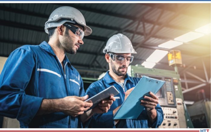
Last month we began the discussion about the relationship between combustion safety and uptime, highlighting how combustion safety, reliability, emissions, and efficiency are inseparable. This month, we will explore the subject in greater detail and outline a path that can both reduce the risk of an incident and protect the bottom line.
This article written by John Clarke, technical director at Helios Electric Corporation, appears in the annual Heat TreatToday 2021 Buyer's Guide June print edition. Return to our digital editions archive on Monday June 21, 2021 to access the entire print edition online!
John B. Clarke Technical Director Helios Electrical Corporation Source: Helios Electrical Corporation
How many times have we heard the tale about the man with the leaky roof? He cannot fix his roof when it is raining, and the roof doesn’t need repaired when it is not. This story is also applicable to heating system maintenance, perhaps more so than other plant maintenance activities because it so seldom “rains.” Ovens and boilers tend to be very reliable. (This statement is true for equipment operating at low or moderate temperatures, less so for equipment operating above 1832°F (1000°C).) It is exactly when the machine is properly producing parts that the planning for combustion safety, availability, and performance must occur.
The first critical step we must take is to understand that combustion safety, routine maintenance, tuning, and calibration are parts of a larger work strategy. To focus solely on the annual inspection of safety components while ignoring system tuning will not only compromise tuning and efficiency, but also the safety. We have seen how managerial reactions to high profile incidents have caused some firms to dispatch teams to annually examine valves and pressure switches. This effort is highly compromised if it does not include all aspects of system maintenance as well as capturing what is learned each time to improve future inspections and equipment designs. There is data beyond pass and fail that is valuable if we wish to optimize the performance of our equipment
Let us assume it is a clear sunny day, and we are ready to invest some time in preparing to improve our combustion system starting with a deep dive examination of two pressure switches: the low fuel gas pressure switch (LFGPS) and high fuel gas pressure switch (HFGPS). These ubiquitous components are present on nearly every fuel train and are vital for safe operation. As their names imply, they monitor the fuel pressure and shut the safety valves if the fuel gas pressure is either too high or too low.
These switches must be listed for the service they provide by an agency independent of the manufacturer – UL, TUV, FM, etc. Simply looking for a stamp may not be enough; take the time to read the file or standard being applied by the agency and determine if it describes the application. Next, ask if the pressure switch carries the basic ratings expected, like the enclosure rating (Nema or IP). Is a Nema 1 switch operating in a Nema 12 area? Temperature ratings must be confirmed. All too often a component rated for 32°F (0°C) is applied in an outdoor environment in cold climates, or one with a maximum rating of 120°F (50°C) is applied next to the hot wall of a furnace. The component may operate out of specified environmental ranges for some time, but to apply a component in this manner is betting against the house – sooner are later we are going to lose. Ask the people of Texas if the bet against sustained cold temperatures in early 2021 was worth it.
"John Clarke, Technical Director, Helios Electrical The first critical step we must take is to understand that combustion safety, routine maintenance, tuning, and calibration are parts of a larger work strategy"
Next, let us look at the contact(s) rating of the switch and how it is applied to the burner management circuit. More often than not, these switches are in control circuits fused for more current than the contact rating. If the switch rating is too low, the electrical designer has an option to use an interposing relay to increase the current carrying capacity to this device. This relay is an added component, and as such, adds yet another possible point of failure. If the relay is interposed, is it dedicated to this one switch? Multiple devices being interposed by a single relay is prohibited by NFPA 86, for good reason. Is the relay designed to fail safely? That is, will a relay coil burn out or wiring fault close the critical safety valves? Is the wire gauge suitable for the current carried and protection device used?
Next, is the switch mounted in a safe location free from possible vibration or the foot of an eager furnace operator? If the switch must be changed, are clearances provided to perform this maintenance? What is the mean time to replace (MTTR) the component? Is the way the device is wired providing a path for combustible gas to enter the control enclosure and cause an explosion? Flexible conduit, without a means to seal the connection, is a very common error. Use a properly specified cord and consider using some type of connector to terminate the wiring at the switch. A simple 7/8-16 or DIN connector not only provides additional protection from combustion gas getting into the electrical conduit but is also a great benefit when changing the component in a rush and helps to isolate the component’s control circuit during testing and calibration.
Is the pressure switch suitably protected from bad “actors” in the fuel gas? Perhaps soot is present that could foul narrow passages or H2S that could result in corrosion. These are rare conditions, but coke oven gas may not be as clean as purchased natural gas. Do we need to specify stainless steel components? Would a filter make sense to protect the switch and increase the intervals between maintenance?
Finally, let’s discuss pressure ratings. Unfortunately, nomenclature varies by manufacturer. What is the maximum pressure the device can sustain and not fail, i.e., leak fuel gas into the environment? Many switches can experience a pressure surge without risk of leakage, but the high-pressure event will damage the switch internally. It is important when determining if this rating is adequate to consider possible failure modes that might expose the pressure switch to excessive pressure. As a rule of thumb, a pressure switch must be able to sustain a surge pressure delivered to the inlet of the pressure reducing regulator immediately upstream of the device. Think of it this way, if the upstream regulator experiences a failure, the full pressure delivered to this regulator will pass to the pressure switch in question.
Other obvious pressure ratings are the maximum and minimum set points. The pressure switch should be set to trip as close to the middle of the range as possible and should never be set close to either the minimum or maximum setpoint. Is the pressure switch manually or automatically reset after a trip? In general, it is best practice that the LFGPS resets automatically, and the HFGPS requires a reset by the operator. This recommendation is because LFGPS trips each time pressure is removed from the system, and it is generally understood that the system needs fuel to operate. On the other hand, a high-pressure event is exceedingly rare, and the operator should be made aware of this unusual event.
This article has discussed a lot about the simple pressure switch. It appears to be a heavy lift to perform this analysis on every pressure switch in a facility, but take comfort, once the exercise has been completed on the first system, it is much easier to replicate what has been learned to properly assess other systems. We should most definitely insist that our OEM provides this data, in detail, when new equipment is supplied. Why did we review all these specifications? Because I have been around for a while and have seen nearly every one of these errors in the application of pressure switches on operating combustion equipment.
Next month, we will expand on the pressure switch discussion to describe the tune/calibration and testing processes. I hope this deep and specific dive has been of value. If you have any questions or comments, please let me know.
About the Author:
John Clarke, with over 30 years in the heat processing area, is currently the technical director of Helios Corporation. John’s work includes system efficiency analysis, burner design as well as burner management systems. John was a former president of the Industrial Heating Equipment Association and vice president at Maxon Corporation.
With the popularity of dry pumps in furnace operations, vacuum furnace operators need to "have a handle" on how to operate them.
In this best of the web feature, the author explains the principles of operation, screw pump design, and various other screw pump characteristics. Learn about the 5 phases of dry pump operation and more in this succinct article.
An excerpt:
"Dry pumps represent a technology that is of interest to many heat treaters as they strive to increase performance and minimize cost and downtime. The advantages of these pumps are comparable to their oil sealed rotary vane cousins, and in certain applications, offer distinct advantages."
Sometimes our editors find items that are not exactly “heat treat” but do deal with interesting developments in one of our key markets: aerospace, automotive, medical, energy, or general manufacturing. To celebrate getting to the “fringe” of the weekend, Heat TreatToday presents a Heat TreatFringe Friday with this press release which describes the energy and sustainability benefits of a recent partnership between a supplier of refractory elements and the National Renewable Energy Laboratory.
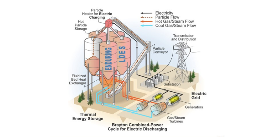
Allied Mineral Products is providing refractory expertise on a new project that will collect and store unused renewable energy. They’ve teamed up with NREL (National Renewable Energy Laboratory) on the ENDURING project, which focuses on long-duration energy storage using heated particles. Funding was awarded from ARPA-E, a government agency advancing high-impact energy technologies in the early stages of development with the idea that some could be transformative and powerful for the future.
The process in development can collect excess electrical energy and convert it into thermal energy. With the help of refractories in a holding vessel, this thermal energy can be efficiently stored for days. When it is needed, the stored thermal energy will go through a heat exchange process and be converted back into electricity for use by commercial or residential customers.
Reducing heat loss is critical as the proposed facility would provide electricity for several days with low-cost particle thermal energy storage. Allied is also selecting innovative products for use in other areas of the proposed plant that would experience high temperatures and wear. Specimens and testing of different refractory materials are being provided by Allied in support of these goals.
Heat TreatToday publisher Doug Glenn finishes his conversation with Mark Hemsath about metal hardness basics. Mark, the vice president of Sales - Americas for Nitrex Heat Treating Services, was formerly the vice president of Super IQ and Nitriding at SECO/WARWICK. Learn all about the what, why, and how of hardening. This episode builds upon previous episodes in Part 1and Part 2.
Below, you can either listen to the podcast by clicking on the audio play button, or you can read an edited transcript.
The following transcript has been edited for your reading enjoyment.
Doug Glenn (DG): This is our third episode with you, Mark, and the first episode basically we were just dealing with very general, kind of like “Hardness 101” – what is it, why is it important, what materials can be hardened, etc. The second episode we delved a little bit further into specifics processes like carburizing, nitriding, etc. If any of the listeners are listening now, they haven't listened to episode one and two, I would recommend that they go back and take a listen to those at their leisure. What we wanted to do today really was just deal with some of the newer advances, why we're seeing some of those newer advances, why some of the processes are having a bit of a resurgence and talk through some of those things.
What we want to do today is to just deal with some of the newer advances, why we're seeing some of those newer advances, why some of the processes are having a bit of a resurgence and talk through some of those things.
Before we start, I'll just ask you straight up, is there anything from the last episodes that you think we need to reiterate or review, or do you think we did okay on those last ones?
Mark Hemsath (MH): I think we did well, and I just wanted to say thank you, again, for letting me talk about this. I think these are some great subjects and I really enjoy doing this.
". . . nitriding, and really its cousin FNC (ferritic nitrocarburizing), are actually fairly inexpensive treatments and they can be performed on final dimension parts. There is no post machining and there is minimal distortion. That's kind of my opinion of why it has done well."
DG: Let's talk about this: From my perspective, from what I hear around the industry, nitriding seems to be getting a lot of play time, to throw in a radio term. You hear it a lot. Why is that? Why is it that nitriding seems to be growing in popularity?
MH: Well, Doug, if you were to ask me, which you did, I think it's mainly due to the discovery that nitriding, and really its cousin FNC (ferritic nitrocarburizing), are actually fairly inexpensive treatments and they can be performed on final dimension parts. There is no post machining and there is minimal distortion. That's kind of my opinion of why it has done well. Like I said, nitriding, not quite as much as FNC; they get lumped together but they are distinctly different.
DG: So, FNC is really the most cost saving?
MH: Yes, you're going to get a fairly hard surface on the part at fairly short cycle times and low temperature. So, again, you can use that final dimension part. You can control that white layer or compound zone, not only in terms of thickness, but also in terms of composition, in other words, how much epsilon versus gamma prime, and its porosity. This allows for repeatable results and repeatable performance today. This was not as easy 20 years ago, but it is today.
DG: And that's because?
MH: The enhancements of the equipment and controls technology. We've come a long way with process control, and that sort of thing; it's substantially different. I always make a joke when we do proposals for equipment, the thing that changes all the time is controls. Electronics are constantly changing and improving.
DG: One other question about nitriding before we move off of that: Are we seeing that growth in popularity in any particular industries or any particular types of products, or would you classify it as across the board? You and I have spoken before about brake rotors and things of that sort.
Find out more on nitrocarburizing by clicking the image above.
MH: It has, you're correct. They've found new uses for it, and brake rotors are one excellent example. Whole new companies have emerged just to do that sort of process because of the volumes that are out there. I think a lot of things are being done. The nice thing about FNC white layer generation on a part is it also has corrosion control, and for automotive that makes a lot of sense. They're discovering new uses for FNC. And then nitriding, in general, has the ability in a lot of instances, as well as FNC, to replace carburizing, depending upon how you engineer the part. There are a lot of reasons to be using nitriding.
DG: You mentioned carburizing, so let's talk about the next process that I'm hearing a lot about, and that's low pressure carburizing. Is it actually growing in popularity? Are we hearing more about it? And if so, why?
MH: This is when I think it's a bit different, in my opinion. I think the surge came many years ago when automakers discovered LPC and it had a lot of good benefits at the same time. Now, aerospace has discovered it but the volumes aren't as high as they were with automotive. LPC is a great process, however, I have been scratching my head as to why it has not become more prevalent, and I think I might have some answers for that.
DG: What are they? Why not more prevalent?
MH: First, many applications of LPC, being vacuum in nature, were performed with high pressure gas quenching. Quenching with high pressure gas limits both load size and materials that you can use that can be quenched in gas, as well as some part geometries, thicker cross sections, etc. They're very hard to quench when you're dealing with certain steels or alloys with high pressure gas quenching. Carburizing, which LPC is trying to replace or compliment, it's really a high volume championing of surface hardening. Hence, per pound, prices are low. Loads are large and dense and you bring in a better quality methodology but you have a lot of limitations on productivity. It's going to get more expensive.
DG: So, you're saying the reason LPC (low pressure carburizing) hasn't taken off is because of the high pressure gas quenching essentially, because you have to do smaller loads?
MH: Yes. To get good quenching with gases because of the nature of how the gases flow around the parts and quench them, even at 20 bar nitrogen or helium, it's just extremely difficult to get the quench rates for certain steels that are required. It is very easy with liquids.
DG: Right. So, you've got to either lighten the density of the load so you get more of the gas flow, or more loads or whatever.
MH: Yes. In vacuum processing typically they spread the parts out further. You have to do that for gas quenching because, depending upon where the gases come from, you don't want to be having one part in the path of another part because you're not going to get the same quench rate. That's still somewhat possible with liquids like oil or water polymer, but certainly not as predominant.
DG: So that begs the question: Can we do LPC with an oil quench or some sort of quench? It's not high pressure gas?
MH: Yes. And it's been done for quite a long time. They call it low pressure carburizing or vacuum oil quenching. You can do both through hardening and carburizing in a vacuum chamber and then you can transfer to oil quenching. Typically, the way that's been done, over all the years, is you transfer it in-vacuum from the vacuum heating chamber to the vacuum that's over the oil and then you put it into the oil. That's what you call classical vacuum oil quenching.
DG: We're talking about high pressure gas quenching and density of loads and things of that sort. One of the things I have been hearing about is companies trying to do more either small lot semi-continuous processes or, in fact, single piece flow so that they can get around the issue of having to oil quench, they can, in fact, do single parts, high pressure gas quenching and things of that sort. Comment on that for a little bit. Are you seeing a growth there?
MH: As you know, we do offer that product line for single piece flow, so yes, we've been working at it for many years. One of the driving forces behind single piece flow is that people are already doing it with so-called press quenching. In those instances, they're taking it out of, typically, a reheat furnace, taking the part out one by one and putting it into a fixture and then quenching it with oil in the fixture to stop distortion as that product cools.
That's a very slow process, very expensive, and very labor intensive unless you can automate that with robots etc. It typically, like I mentioned, involves, if you're surface hardening, you're probably going to do that in a separate unit, carburize that, slow cool it and then you're going to put it back into a reheat furnace. So, it really adds to the cost of those parts, but you get some tremendous distortion control on the parts.
"What we're seeing with [press quenching] is the distortion is very, very low, we're not using any oils, we're not using a press quench, we have very low labor inputs and we can put it in line with the manufacturing cell. The only issue with that technology, and one of the reasons it's been a little bit slow to grow, is that you need relatively uniform part sizes and shapes and pretty large volumes. But this would usually be part of the process plan."
DG: That's in press quenching you're talking?
MH: Yes, that's in press quenching. Now, what we've come up with is something that we call a UniCase Master when you're doing case hardening with it, we also utilize what we call our 4D Quench. The 4D Quench is a high pressure gas quench that actually takes many, many nozzles of high pressure gas and puts it right on the part. The fourth dimension is that we actually spin that part. If you have an irregular gear, you're getting that gas distribution that's coming out of many, many nozzles, distributed very uniformly all over the part.
What we're seeing with that process is the distortion is very, very low, we're not using any oils, we're not using a press quench, we have very low labor inputs and we can put it in line with the manufacturing cell. The only issue with that technology, and one of the reasons it's been a little bit slow to grow, is that you need relatively uniform part sizes and shapes and pretty large volumes. But this would usually be part of the process plan. We've come up, now, with some varieties of that where we can actually change that 4D press quench to cover a range of sizes and you can program that into the software.
DG: And on the 4D Quench or the UniCase Master in the quenching process, are you able to treat most of the grades of steel, even oil quench graded, most of those, or is it fairly limited?
MH: No, it's actually very good. What we've found is, because we're concentrating that cooling of the high pressure gas is very close to the surface. I've mentioned before- you're in a batch load, let's say you're in a 24 x 24 x 36 inch load geometry with high pressure gas quench, well those gas nozzles are coming from very far away. If you go to more standard large size, like a 36 x 36 x 48 inch, the nozzles are even further away from the source. So, yes, you're getting mass flow across the products, but you're not getting much impingement. In convective cooling you need jet impingement. I spent my whole life on this. As you may recall, I was involved with my father and he had patents on jet impingement. We come from a long history of working with convection and jet impingement. Our 4D Quench perfectly optimizes those gas jets coming out and at 4, 6 or 8 bar, we can do the same cooling rate on a gear that you can get with oil. That's phenomenal.
DG: How about some of the other advances that we've seen? I've got a couple of others thrown down here that I'd like you to comment on. Again, for the listeners, I want the listeners to know that Mark's a very gracious guy. Even though he works with Seco Vacuum, I've asked him to comment on some other products that are not his, but he'll give you a good perspective on these things, at least an introductory perspective.
Let's talk about hybrid systems, if we can. We're talking about an integral quench-type system which is where a lot of this hardening process goes on that we've been talking about. Talk about the hybrid system.
MH: As we talked before, the vacuum oil quenching has been done for a long time as has integral quench furnaces. Gas carburizing or gas integral quench furnace has remained pretty much the same for 50 years. You utilize an oil quench, you try to get as quickly as you can into that oil quench, you have agitation in the oil, which gives you pretty decent quenching. When you do that in a vacuum oil quench, because you're putting a vacuum over the oil, you'll get too much out-gassing with standard oil so they've had to develop special oils for vacuum oil quenching.
A couple things with vacuum oils: Number one is they're not as fast, they're slower quenching because of the nature of how they make them and the other thing is they're kind of hard to wash off. They tend to varnish on and give you more problems with that. People that have to do vacuum oil quenching have learned to like it and do it, but people that are used to doing standard interval quench furnaces, if they like oil at all, which a lot of them don't, a standard oil integral quench furnace has fairly fast oil. That allows you to put some pretty good sized loads, a lot of productivity, through a standard interval quench furnace.
What we decided to do was, we said, we want to keep that standard interval quench, and if we do that and marry it to a vacuum chamber that can do low pressure carburizing, how would we go about employing that? We were able to create a furnace that did that. We're using a standard quench standard oils and instead of having endogas as a blanket atmosphere, we use only nitrogen, dry pure nitrogen.
Then, in the heating chamber, number one is that if you're doing through hardening, you don't have any atmosphere; you're under vacuum. The good news with being under vacuum is that you don't have any problem with decarb or picking up carbon of your part. Under vacuum, the nature is that the carbon does not move around, it does not leave the part, and it does not go into the part. It becomes very easy. Regular integral quench furnace, you have to condition it and try to get it at the same carbon potential that you have in your part. It gets a little tricky. With this furnace, it's very, very simple.
As far as carburizing, when you do it in a low pressure mode – what we call LPC (low pressure carburizing) use only acetylene – you're doing it at fairly low pressure levels, typically in the 5-10 bar range and you're using just acetylene. You're using what they call a boost diffuse. Now the key to doing low pressure carburizing, and one of the reasons I think that it has had some issues is in the past, is you need good simulation software. We happen to offer one called SIM-Vac* and it has years and years, if not decades, of experience behind it so that it's now a very handy tool for the heat treater to know what his cycles and recipes are going to look like in an LPC type furnace.
DG: Basically, you're doing a vacuum heat cycle, pulling it out of vacuum into a nitrogen chamber and dunking it into a standard oil quench.
MH: Yes. We will back-fill with nitrogen at the end of the cycle. You typically want to drop a little in temperature anyway before you quench, so there's no problem putting cold nitrogen in there. You get to your transfer temperature and you transfer into the oil.
DG: Cost comparison between a full vacuum oil quench and this hybrid type system?
MH: We've done quite a few. We have two things going against us. We have electric heating and we're using nitrogen. However, the gas guys have quite a bit of gas usage because they're using endo generators and there is quite a bit of energy consumed in those endo generators. When you do the comparison, in a same temperature processing scenario, it's about equal.
However, because our equipment can go to higher temperatures without any challenge at all to our heating furnace, we can go with much faster carburizing cycles. So, when you start those shorter carburizing cycles, you're using less energy and you're using less gases. We actually will end up being a little more competitive. It's kind of counter intuitive, but this is how it really is helping us. Only going 100 degrees Fahrenheit higher, which is not very uncommon going from 1700 to 1800 degrees Fahrenheit, results in almost 50% faster carburizing times.
DG: You're actually being more efficient with your equipment.
MH: Very efficient. And you'll actually get more productivity out of our units if you take advantage of the higher temperature. By going 100, 150, 200 degrees higher in Fahrenheit, you're not going to hurt the furnace, unlike a gas fired radiant tube where you're going to tear it up.
DG: Comment a little about the true vacuum oil quench systems.
MH: They are wonderful systems. We make a great one called Case Master Evolution and we've had that for over 10 years. It's a great product line. A lot of other furnace companies have it. I just read that one vacuum furnace company is going to be offering it in the next year or so. I saw another vacuum furnace came out with a new line kind of touting the ecological aspects of it. But we've been doing it for a long time, so we know how good it is.
The only issue with the vacuum oil quench is the equipment is a little more expensive. For aerospace, that's not a problem. The equipment is typically not quite as productive and it costs maybe 50% more than standard, basic integral quench furnaces. That's why we came up with, what we call, our super IQ- try to get the costs down and have the benefits.
Then, based on that, can we also increase the productivity? We found that we could and it turns out to be much more advantageous money-wise. However, there are still specifications, there are still people that want to have that vacuum to vacuum transfer. There are people that want to have that type of aerospace grade type processing. Our equipment has done very well and I'm sure some of the other guys are selling theirs as well.
DG: So, there is still a place, obviously, for a full vacuum oil quench system. Back on the hybrid then, are there other companies that you know of?
MH: No, I'm not aware of any.
DG: So, the hybrid system, basically at this point, you guys are the only ones doing it.
MH: There are two barriers to entry, obviously, into that market. One obviously is having the vacuum oil quench technology and then converting that technology to what we have which is nitrogen gas, etc. The other thing is, as I mentioned before, if you don't have the simulation programs, it's going to be hard for you to place it into very high production shops. In an aerospace shop, you've got a lot of high end people around that can do that for you, that can set up the recipes, etc. If you're in a basic commercial heat treat shop, you're not going to have that kind of personnel who can be doing that on cycles that change fairly rapidly, without a good tool, and we have that tool.
DG: I want to ask you one last question. It's kind of unrelated, kind of related, a little bit different. We had a podcast we did recently, a four part series we did with Joe Powell with Integrated Heat Treat Solutions. I'm curious your opinion on this. He talked about this process of basic quenching, getting the whole surface of the part down to the martensite start temp which basically forms a case around the part and then you can, basically, slow conductive cool from the core inside out. It has to do with hardening, so I wanted to just throw it out to you. Did you get a chance to listen to those podcasts or parts of them, and what do you think of that whole process?
MH: I did. As you requested, I looked at the podcast on intensive quenching by Joe Powell. I'll tell you that, I actually can't remember which show it was, one of the last or two heat treat shows, I actually ended up sitting next to him out in the hall somewhere and he handed me a piece of paper and said, “Here! This is what we're doing.” I was exposed to it before, but I got into it more now that you showed it to me. It certainly is science based and he understands the issue of quenching very well. I point out that our 4D Quench solves many of these issues, but he's coming from his angle on it, and I certainly agree with him.
As you may recall, I probably mentioned it before, my father was in the industry and had 65 patents, mostly heat treat related inventions. Rarely did we make money off of these ideas. So, I'm used to a lot of great ideas, but you can't make money. I think it's challenging in this world of mass production heat treating, where we have carburizing being performed at 50 cents a pound to get engineers, like Joe is wanting to do, to focus on the whole part life cycle and combining that final quench phase with the part design. I think it's a great idea but I just think it's hard to do.
We kind of know this from experience, and I won't get into it too much, but I think you may know that we have a process called PreNite where we prenitride our parts. That is a similar type thing where we're trying to take advantage of things that we know are possible in heat treating and prenitriding it allows the grains to not grow when you go to higher temperature to try to get more productivity out of a piece of equipment.
The one thing you've got to do, though, is convince the engineer to use a different alloy so that you don't get grain growth in the core. Convincing those guys is tough. We just don't see engineers engaged enough to do this complex reengineering. That's my opinion only. I think that's where Joe is going to get some resistance. I think his ideas are great, and of course, I totally agree with his approach to it. I could go through some other ideas that I came up with just reading his is almost like should you misquench first before you dunk it in the oil so you get that outer case, as he talked about. I think it's a lot of great of ideas.
What we need to do is find some really good engineers to break the barrier of those low risk takers that we have in engineering, and I think that's possible. You may know everybody's out there talking to people like Tesla and SpaceX and some aerospace companies. These guys are starting to break some of these barriers. They're starting to saying we don't want to do the status quo, we want to do something different. If we can do that, a lot more of these technologies will take off.
DG: We need some early adopters to step up.
MH: Early adopters. And people who want to not just be yes-men but really think it through – the whole life cycle of a part, how it's designed and everything else.
DG: So, dear listener, if you are one of those people, please call us. We're interested. We've got a couple of different technologies. Mark, thanks a lot for your Hardness 101 and helping us out on these three. I think we covered some good ground.
Doug Glenn Publisher Heat TreatToday
To find other Heat TreatRadio episodes, go to www.heattreattoday.com/radio and look in the list of Heat TreatRadio episodes listed.
Eurometal S.A., member of the Eko-Świat Group and manufacturer of highly processed aluminum products, purchased an aluminum coil annealing atmosphere furnace. This solution will be used by the only rolling mill currently in operation in Poland, with Polish-owned equity.
The new equipment is the third for this client from the parent company of North American furnace manufacturer, SECO/VACUUM. The SECO/WARWICK solution will consist of a Vortex® furnace for aluminum coil annealing and will be equipped with an external cooling system. The by-pass cooler will be for cooling under a nitrogen atmosphere, and SeCoil® — the control and simulation software — enables aluminum coil manufacturers to significantly shorten the production cycle.
The SECO/WARWICK solution will be used by the only rolling mill currently in operation in Poland, with Polish-owned equity.
As a result, Eurometal S.A. will benefit from the system in energy saving, increased productivity, and improved the surface quality of the processed coils. The key feature of the system is the increased heat-transfer coefficient, due to directing the atmosphere at a high speed simultaneously on both sides of the coil.
Sławomir Woźniak CEO SECO/WARWICK Source: secowarwick.com
Aluminum is an extremely plastic and light material, resistant to corrosion and many chemicals. Precise parameters of aluminum sheet enable its use for manufacturing various types of products and semi-finished mill products. Aluminum is used in the aerospace, automotive and machinery industries. Also, the construction sector uses aluminum sheet made with alloys characterized by high corrosion resistance and good forming ability. The ship building industry has also many applications for this alloy. Aluminum is certainly a crucial material for the development of many sectors.
"Aluminum replaces other conventional metals, in particular in modern state-of-the art products," commented Jarosław Śliwakowski, Eurometal S.A. "The automotive industry, with the dynamically growing share of aluminum, is at the forefront of replacing conventional metals[. . .] We have chosen Vortex due to the shortening of the total process time, even heating of the batch and reduced natural gas, protective atmosphere and electricity consumption in comparison with the products proposed by the competition."
"Eurometal has been our partner for many years," said Sławomir Woźniak, CEO of SECO/WARWICK Group. "[. . . ] From the very beginning, our cooperation has been based on trust. We always focus on approaching each order individually. We create a flexible system design, custom-made for the needs of a particular rolling mill."
"SLM"? You may have heard of AM -- additive manufacturing -- but how about selective laser melting, SLM? Stay on top of your acronyms with this overview on how vacuum furnaces and SLM, an AM technology, can increase fatigue performance of parts.
In this Technical Tuesday, the author not only shares what this technology can do, but also the results of SLM in laboratory studies and research at the University of Parma.
"When SLM processes are conducted within a vacuum heat process, it is possible to make more detailed components which have more intricate forms. Crucially, this means that they will often perform better than would otherwise be the case when they are in use."
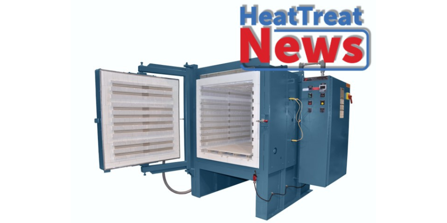
A US manufacturer of radio frequency (RF) and microwave components recently received a small box furnace reaching 2300°F. This furnace will be used for precision heating to anneal their parts before milling.
The small load custom box furnace was delivered by Lucifer Furnaces. It is their furnace model HL7-A12 with a 6” x 6” x 12” chamber and is insulated with a combined 5” hot face insulating firebrick and cold face mineral wool backup. This box furnace is complete with a cast hearth plate to protect the floor insulation and heats with easy-to-replace coiled heating elements in cast assemblies for easy replacement, while still being built at the same quality as larger models.
Controls include a Honeywell digital time proportioning temperature controller and a TP1 Soak Timer which starts when the furnace reaches setpoint temperature and shuts off the elements at the end of the heating cycle. A door safety switch automatically disengages power to the elements when the door is opened. This furnace is part of Lucifer’s standard, general purpose, series 7000 box furnace line, a line which helps bring clients’ heat treating in-house and gain control over work flow and product quality.
A U.S. independent chemical distributor and manufacturer of surface treatment chemistry announced that it has acquired the assets of Arbortech, an Illinois-based manufacturer of patented membrane equipment. With the acquisition, the manufacturer becomes the first chemical company to offer specialty cleaning formulations designed specifically for the patented membrane separation technology.
This refers to Hubbard-Hall's Aquaease Infinity® platform, a complete cleaning and reclaim system, designed to save manufacturers up to 35% on chemistry while also reducing process defects.
The acquisition solidifies a longstanding relationship between the two companies. Aquaease Infinity® was the first line of degreasers and cleaners co-developed for use with Arbortech’s unique membrane technology. Unlike standard industrial cleaners/degreasers, the Aquaease Infinity® cleaning compounds fully pass-through Arbortech’s membranes, leaving soils and oils trapped. This guarantees the reclaimed cleaner is "as new" and remains a full-strength product. Customers report retaining 98% of their cleaning baths and reducing waste and total cleaning costs by 35% or more.
This development in cleaning technology gives customers more control over their cleaning processes, extends the life of the cleaning bath and reduces downtime and waste. The system is offered as a lease to reduce upfront capital costs.
"Hubbard-Hall is on a mission to help customers get better results with less chemistry, process complexity and, ultimately, lower costs,” noted Molly Kellogg, CEO of Hubbard-Hall. "By adding the Arbortech team and technology to the Hubbard-Hall product offering, we plan to aggressively expand the Infinity platform to industrial manufacturers seeking to improve quality while reducing cost and environmental impact."
Ray Graffia, Jr. Founder and President Arbortech
"It’s nice to be part of the Hubbard-Hall family," added Ray Graffia, Jr., founder and president of Arbortech. "This is a like-minded company that shares our value for sustainability and can expand the use of membrane technology into new areas. It just makes tremendous sense."
Bill Egerstaffer will join the Hubbard-Hall staff as equipment engineer. With 25 years of experience at Arbortech, Egerstaffer is responsible for the fabrication, installation, maintenance and design of the membrane units as well as programming the controllers. He will report to Mike Frechette, Business Development Manager.
The acquisition brings together more than 200 years of combined experience and a shared vision to create sustainable business.
An optical laboratory in northeastern USA will receive a second floor-standing box furnace for heat-treating ceramics and optics used in the medical field.
The L&L Special Furnace Company model XLE 3636 has an effective work zone of 34” wide by 30” high by 32” deep. It features a double pivot horizontal door. The ceramic hearth is supported on lightweight castable piers. A series of heat shields are included to ensure a safe case temperature while at operating temperatures. The furnace is designed for use with inert blanketing gas for atmosphere control to minimize oxidization. A manual flow panel with regulator and flow meter is included.
A Eurotherm program control and high limit safety are standard. The furnace has a stack light mounted to the top of the control panel for an audible and visual indication of current furnace status. Solid-state relays drive the furnace, which is NFPA86 compliant. Startup and training packages are also included to help the customer set up the furnace and process.
Neota Product Solutions, a custom metal injection molding (MIM) manufacturer located in Loveland, Colorado, has recently partnered with a North American heat treat supplier to develop an exclusive sintering partnership.
Jason Osborne President Neota Product Solutions Source: LinkedIn
Neota provides comprehensive MIM solutions from early-stage prototyping to full scale manufacturing. The manufacturer and Solar Atmospheres of Western PA (SAWPA) developed a sintering thermal profile that densifies complex geometric shapes and also controls shrinkage. This results in a solid and strong metallic part, with near 100% density, while maintaining the tight tolerances that are required in their precision components.
Collaborating with Solar Manufacturing, the vacuum furnace production arm of the Solar family, SAWPA recently acquired a vacuum furnace which is engineered to handle MIM processing. The furnace has a work zone of 36” x 36” x 48” and a load capacity of 3,000 pounds.
Robert (Bob) Hill, FASM President Solar Atmospheres of Western PA
"Solar has been a class-act organization and has been instrumental in the aggressive growth of our company," stated Jason Osborne, president of Neota.
"We have sincerely enjoyed our relationship with the Neota team," added Bob Hill, president of Solar Atmospheres of Western PA stated. "As MIM industry experts, they know what they ultimately want in a finished part. As vacuum thermal processing specialists, we know how to achieve their high temperature processing parameters while not damaging our state-of-the-art vacuum equipment. Investing in our customer’s needs, ultimately results in lasting mutual relationships which become a successful endeavor for both parties."


 Last month we began the discussion about the relationship between combustion safety and uptime, highlighting how combustion safety, reliability, emissions, and efficiency are inseparable. This month, we will explore the subject in greater detail and outline a path that can both reduce the risk of an incident and protect the bottom line.