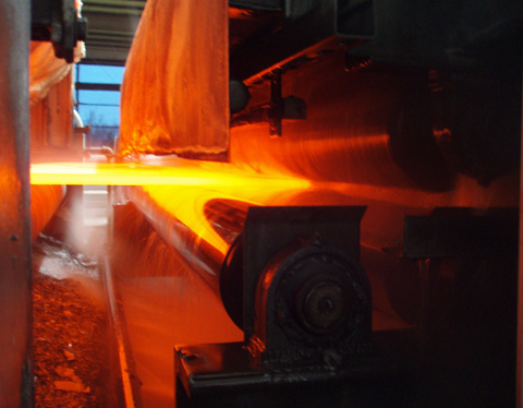
A global producer of highly engineered metal earth moving, construction, and mining wear equipment recently commissioned two large capacity heat treatment furnaces. As part of this turn-key contract, Can-Eng Furnaces International Ltd. designed and commissioned individual tempering and stress relieving furnaces. Both heat treatment systems were assembled and tested at Can-Eng’s Niagara Falls facility prior to shipment and commissioning at the customer’s facility.
The furnace systems were part of a major expansion by the customer to satisfy increased demand for large steel castings and weldments used as part of their equipment designs. Both furnaces are equipped with high efficiency, natural gas-fired heating and recirculation systems that have demonstrated to exceed the requirements of AMS-2750 temperature uniformity. Both systems integrated the company’s preferred PLC hardware, which was upgraded to include a more flexible safety rated PLC over conventional hardwired safety circuits.
Heat Treat Today is privileged to oversee the 40 Under 40 recognition awards highlighting a group of young, up-and-coming talent in the North American heat treat industry every year. This year’s Class of 2019 is no disappointment–a group of industry elite, significant contributors to the heat treat market.
Every couple of weeks we highlight two of the current class of recipients. This week we introduce Uwe Rahn of Rubig USA and Mike Harrison of Gasbarre Thermal Processing Systems.
Name: Uwe Rahn
Company: Rubig USA
Position: Area Sales Manager for US and Canada
Uwe has been in the heat treat world for his whole career, starting in Austria and continuing when he moved to the U.S. on a business visa. In the States, he learned the language and continued to become an expert in nitriding. He currently leads the U.S. team selling and servicing gas and plasma nitriders as well as plasma coating systems.
Nominated by: Mountain Rep
Name: Mike Harrison
Company: Gasbarre Thermal Processing Systems
Position: Metallurgist, General Manager, Engineering Manager
From starting as a metallurgist with a large tier 1 supplier, to running a commercial heat treat plant with a large commercial heat treater, Mike has developed a wide range of experience in the heat treating industry. He is now on the OEM side making a difference in equipment design for our customers. During Mike’s past employment he has helped implement a global ERP system across multiple facilities in multiple countries and has led the charge in launching a brownfield facility, changing it over as a facility for conventional heat treating processes to highly technical precision nitriding processes. Within the company, Mike has standardized capital quoting processes for higher accuracy and efficiency and is now doing the same for the engineering department. Instrumental in the development of Gasbarre’s precision nitriding equipment, he is able to ensure the end user’s daily interaction with the equipment is accounted for in the design. Mike completed his MBA from Walsh College in 2017 and the MTI YES program in 2019; he presented on “Furnaces for Gas Nitriding and Nitrocarburizing” at the 2018 FNA show.
Nominated by: Gasbarre Thermal Processing Systems
Read more about the feature at Heat Treat Today’s 40 Under 40 resource page and find out more about each of this year’s winners by clicking on their image. To nominate someone for the Class of 2020 40 Under 40, please click here.
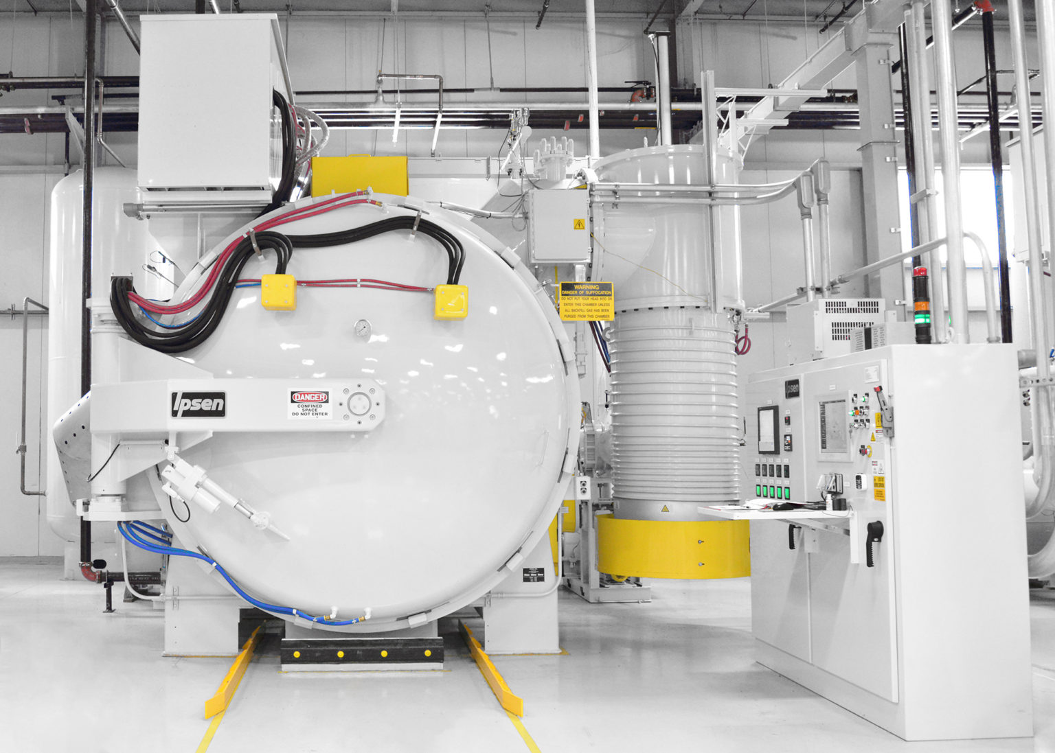
A strong and healthy vacuum furnace system is essential for heat treaters who want to stay competitive and serve their customers well. The heart of the vacuum furnace system is just as critical as the heart of the human body. Just as a healthy heart is essential to living well, keeping a healthy vacuum furnace system pumping strong is essential to certain heat treating operations.
In this Heat Treat TodayTechnical Tuesday Best of the Web feature, Ipsen USA provides tips for how you can get the best performance out of your vacuum furnace by selecting the most appropriate pumping system, and by following a few simple tips for vacuum furnace maintenance over at its blog, Ipsen, The Harold.
An excerpt: “Vacuum furnace systems utilize various types of pumping system combinations to evacuate atmospheric pressure from the vacuum chamber to required ranges for specific processes. Since the heart of the furnace is the vacuum system, it is essential to maintain the pumping system as specified in the operator’s manual, taking into consideration any special accommodations that the type of process being conducted may require.“
This post from Ipsen’s blog guides readers through the basics, troubleshoots common problems, and gives tips for avoiding the heat treater’s primary enemy.
Safety is a concern to all industries, but it’s of paramount importance for the aerospace manufacturing sector. Join us on this whirlwind tour of a heat treat shop from the perspective of an industry safety consultant, Rick Kaletsky. Rick’s a funny guy, but don’t let that detract from the critically important information he has to share. Rick Kaletsky is an MTI OSHA Safety Consultant and the author of the popular book, OSHA Inspections: Preparation and Response, 2nd Edition.
This column is being supplied courtesy of the Metal Treating Institute and was first published in the Heat TreatToday Aerospace magazine in March 2019.
With all of the bright and shiny new gadgets and technology in the heat treat industry, it’s easy to overlook the wealth of the “same old” classic hazards, which may not have been properly dealt with in the shop. It is critical to address these basic (often severe) risks/violations rather than be distracted by trying to identify new-to-the-forefront issues. Please note that this list is surely not all-inclusive. I’ll make this concise as we tour the shop and highlight areas that demand attention.
Let’s take a look:
Are you still allowing obstacles to impede immediate access to exits, fire extinguishers, electrical disconnects, and emergency eye fountains?
Are you permitting unguarded (or improperly guarded) power transmission equipment, highlighted by chain drives, belt drives, couplings, and gears?
Have you adequately guarded fan blades?
Are you adhering to the (chemical) hazard communication program— especially the labeling, safety data sheets, and
training? (Also, don’t forget the Globally Harmonized System.)
Is the lockout/tagout program (relating to unexpected energization and release of stored energy) sufficient— attaining ZES (zero energy state addressing electrical, mechanical, pneumatic, hydraulic, spring, thermal, steam, gravity+), only one “available” key per personal lock, machine-specific procedures, and more?
What kind of permit-required confined-space program have you implemented—a detailed, super priority, tackling matters of oxygen deficiency, vapor ignition, entrapment, and so on, with a fully integrated plan including (but not limited to) space identification, permit system, calibrated instrumentation, attendants, and non-exposed rescuers?
All set now? WAIT! There’s more that is routinely violated on a regular basis. These items above, and more to follow, are not simply matters of technical non-compliance with the law of the land. They are scenarios waiting to ambush workers and leave them with burns or worse (from fire, explosion, and electrical sources), mangled digits and limbs, blindness, lung damage, and many other examples of preventable misery.
Abatement can be motivated by a desire to avoid “breaking the law and paying the price.” It can be motivated by ethics and the sincere “touchy feely” desire to “do the right thing.” Yet it can also be motivated by a company’s knowledge that employee protection is good business, with very tangible, financial results. The cost of occupational injuries and illnesses can decimate your profit line far more than direct medical costs. It is worth considering all of the follow-up medical bills, cleanup, overtime, downtime, insurance rate increases, and much, much more, not to mention the enhanced OSHA penalties.
Pardon the diversion; now for a look at some more key questions:
Is heat stress considered to be a very real concern (and met head-on as an occupational hazard) rather than viewed as a mere matter of degrees of comfort?
Has there been a full assessment of personal protective equipment needs?
Is safety-toed footwear required, as determined by such an assessment?
How about eye protection (consider different forms for different hazards), hand protection (again, particular types for particular risks), hearing protection, flame-resistant/retardant clothing, and whatever else is brought to light by way of a thorough assessment considering each task to be performed?
Are the extinguishers conspicuous, fully charged, and professionally tested on a timely basis?
Who is expected to use the extinguishers, and have those employees been “hands-on” trained?
Are compressed gas cylinders well-secured, capped (where designed to be), and properly separated (oxygen from fuel gas, in storage)?
Have I offered enough tips? No? Okay, here are just a few more points to ponder:
Are electrical cords in good condition, without (for instance) stripped/cut/burned insulation, damaged/missing grounding prongs, or similar damage? (Remember that portable electrical tools can be double-insulated, as an alternative to grounding.)
Is there accurate, unambiguous, easy-to-read labeling on disconnects, breakers, controls, and so on?
If there are breaker slots without breakers, are those spaces filled with blanks?
Are electrical boxes and similar apparatus equipped with approved covers?
Are forklift trucks and similar vehicles properly maintained, with emphasis on steering, brakes, horn, tires, overhead guard, and fork movement reliability; are all operators suitably trained?
How about the elimination or deep mitigation of trip and slip hazards?
What have you done (including by engineering means and specific training) to decrease exposure to ergonomic hazards, especially regarding backs?
There’s always more that can be done to improve safety and minimize risk in the shop, and it’s usually something easily overlooked in regular safety checks that turns up flagged in a review. But don’t let the procedure blind you to the most important reason we stress safety in the shop: the welfare of our employees.
Sometimes our editors find items that are not exactly "heat treat" but do deal with interesting developments in one of our four key markets: aerospace, automotive, medical, or energy. As we approach the weekend, today's Heat TreatFringe Friday, Best of the Web post focuses on an interesting development in additive manufacturing.
The hometown of Mr. Rogers is getting a new additive manufacturing neighborhood. The Barnes Group Advisors (TBGA), a large independent advanced manufacturing engineering consultancy, has released an impact study revealing the overall economic benefits of an additive manufacturing production campus at Pittsburgh International Airport.
Christina Cassotis, CEO, Allegheny County Airport Authority (source: Pittsburgh International Airport)
While the Pittsburgh Airport's other modernization projects have ground to a halt in the wake of the COVID-19 pandemic, Neighborhood 91 has happily been able to continue pressing forward with trying to sign tenants and pursuing plans surrounding the master developer. Overall, according to Allegheny County Airport Authority CEO Christina Cassotis, "We are still seeing interest expressed in Neighborhood 91 from throughout the world."
An excerpt: "According to the study, the innovative industrial park at Pittsburgh International Airport will create nearly 6,000 jobs over the next decade and will generate about $2.2 billion in wages over that same time period. The authors note that Neighborhood 91 will act as a catalyst for additive manufacturing AM industrialization and innovation with the creation of a cost-efficient ecosystem and the collection of smart people."
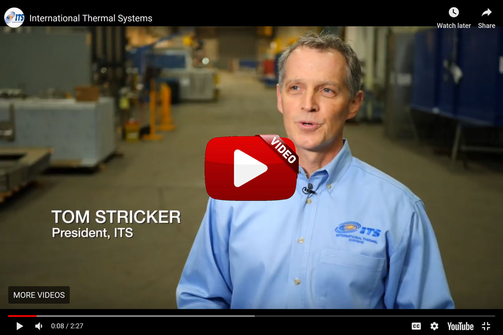
International Thermal Systems’ goal is to help their customers make better products by providing water-based cleaning and heat treating solutions to be used in their processes for manufacturing and fabrication. They strive to be heavily involved with their customers throughout the process, providing custom design as well as building services.
This video demonstrates how its process, customer-centered goals, and continued support over the entire life of the products provided by their craftsmen, work together to give their customers exactly the solution they are looking for.
Click here for more information on International Thermal Systems.
If you have a video you’d like included on Heat TreatTV, please send an email to editor@HeatTreatToday.com and include a link to the video.
Is new technology always an advantage? Do companies need to update everything or a few things? The rapid pace of technology upgrades is dizzying, and many heat treaters can find themselves unsure of whether to embrace it or refuse it.
In thisHeat Treat Today Original Content feature, Gerry McWeeney of Heat Treatment Solutions gives his take on the pros and cons of remote monitoring in heat treatment.
Special thanks to Gerry McWeeney, heat treatment consultant and president of Heat Treatment Solutions, for permission to run this article.
Technology plays a major role today in most industries, and heat treatment is no different. Having been around emerging technology a lot in the last 20 years or so and reviewing recently other types available in the heat treatment marketplace, it is a subject near and dear to me and I was happy to be sought out by friends in the industry to give my opinion on the Pros & Cons.
THE PROS:
SAFETY – This cannot be reiterated enough. By reducing numbers of labor in operating units, remote capabilities reduce the risk for end-user and vendors.
COST REDUCTION – Reduced labor provides a better commercial proposition to end-users on the manpower to equipment discounted rate scenario.
REMOTE START and STOP
Clients can benefit from early switch on to assist getting weld preheat to temperature. While not ideal for every situation, e.g. inside refineries where conditions can change and the need for the buddy system negates commercial benefit, but, in certain situations can assist welder productivity, which helps cost and schedule.
This reduces the risk in emergency situations. The equipment can be remotely isolated without putting people into the units to do this task.
THE CONS:
REDUCED LABOR - At the site, this can have commercial benefits to the customer. It can also have an adverse effect when scope creep or changes to the schedule occur and there are insufficient resources.
LIMITED FIELD EXPERIENCE - Having control and monitoring operators with limited field experience is a risk as they, at times, can be unable to assist adequately when heat treatment or site conditions change.
RULES & REGS - Differing employment rules and regulations across borders and states can have an adverse effect on project harmony between operators and field personnel.
TOO BUSY – Some operators can be charged with monitoring many heat treatments across various different recording devices and projects, some more complex than others. This can cause delays in communications to field when operators have too much on their hands and conditions change. This can be especially true during TAR / OUTAGE season.
The above lists are not complete--there are other softer pros and cons depending on each company’s technology.
Technology alone will not guarantee the heat treatment, that can only be done by correct set up of thermocouples and heating elements in accordance with code requirements and/or engineered drawings that meet code criteria. Technology is here to stay, and advancements in it, when implemented properly, will help vendors and users alike.
“My preference is for control and monitoring at site using remote capabilities with access to view by the client and heat treatment personnel at site”
One of the great benefits of a community of heat treaters is the opportunity to challenge old habits and look at new ways of doing things. Heat Treat Today’s101 Heat TreatTipsis another opportunity to learn the tips, tricks, and hacks shared by some of the industry’s foremost experts.
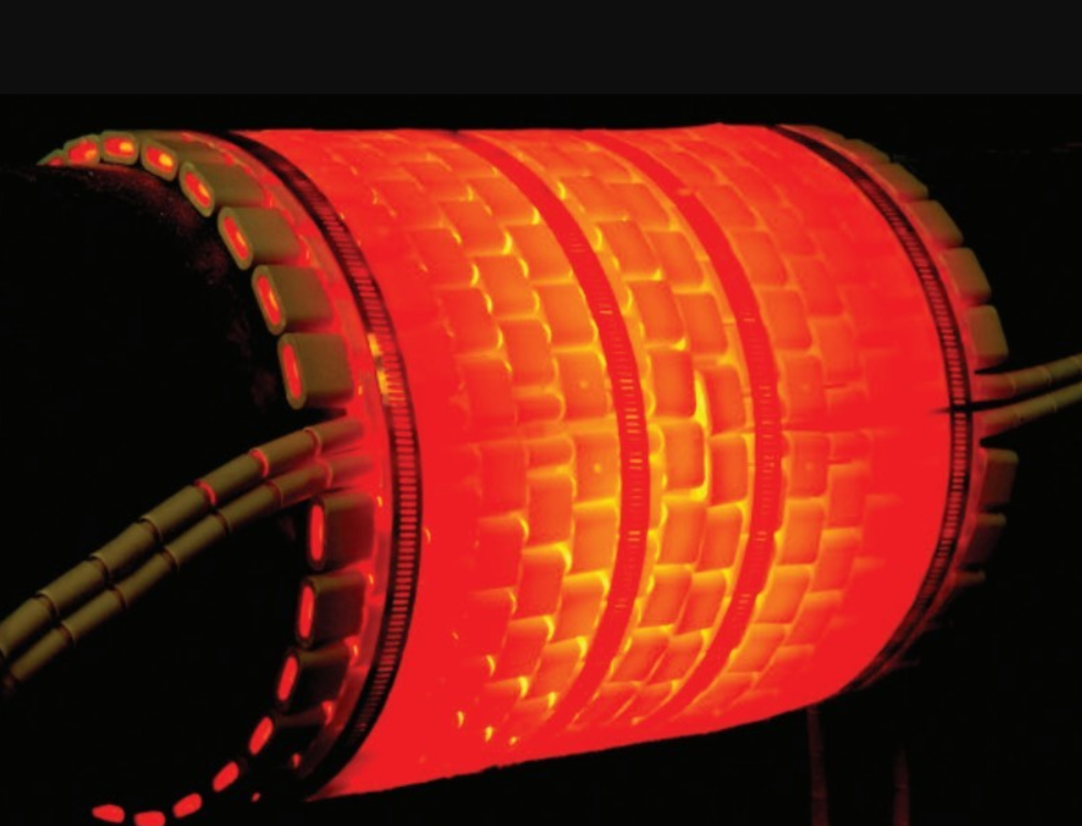
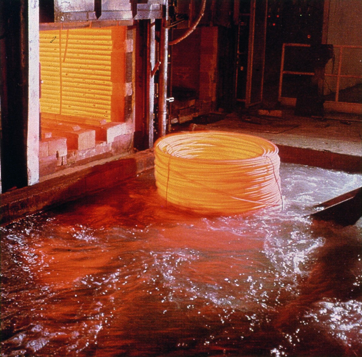
Today’s tips come to us from Quaker Houghton and Contour Hardening, covering Aqueous Quenching. This includes advice about effective filtration in removing particulates in aqueous quench systems and tips for aqueous quenchant selection.
Adding a strong magnetic filter in line after the main filtration system is an effective way to remove fine, metallic particulates in an aqueous quench system.
Submitted by: Contour Hardening
Heat Treat Tip #9
Aqueous Quenchant Selection Tips
Greenlight Unit (source: Quaker Houghton)
1. Determine your quench: Induction or Immersion? Different aqueous quenchants will provide either faster or slower cooling depending upon induction or immersion quenching applications. It is important to select the proper quenchant to meet required metallurgical properties for the application.
2. Part material: Chemistry and hardenability are important for the critical cooling rate for the application.
3. Part material: Minimum and maximum section thickness is required to select the proper aqueous quenchant and concentration.
Aqueous Quenching (source: Quaker Houghton)
4. Select the correct aqueous quenchant for the application as there are different chemistries. Choosing the correct aqueous quenchant will provide the required metallurgical properties.
5. Review selected aqueous quenchant for physical characteristics and cooling curve data at respective concentrations.
6. Filtration is important for aqueous quenchants to keep the solution as clean as possible.
7. Check concentration of aqueous quenchant via kinematic viscosity, refractometer, or Greenlight Unit. Concentration should be monitored on a regular basis to ensure the quenchant’s heat extraction capabilities.
Greenlight Display (source: Quaker Houghton)
8. Check for contamination (hydraulic oil, etc) which can have an adverse effect on the products cooling curves and possibly affect metallurgical properties.
9. Check pH to ensure proper corrosion protection on parts and equipment.
10. Check microbiologicals which can foul the aqueous quenchant causing unpleasant odors in the quench tank and working environment. If necessary utilize a biostable aqueous quenchant.
11. Implement a proactive maintenance program from your supplier.
Heat resistant alloys used for heat treating fixtures, muffles, retorts, radiant tubes, and other parts are typically stainless steel or nickel based austenitic alloys. Welding of these alloys requires practices that are often exactly the opposite of the practices required for carbon and alloys steels since austenitic stainless steels do not undergo phase transformations. Metallurgists are often asked many questions on the proper welding methods. Carbon and alloy steel welding requires practices and procedures that will minimize or prevent the chances of cracking due to potential martensite formation during weld solidification. Austenitic stainless steels do not undergo any phase transformation. They require rapid cooling to prevent solidification cracks due to hot cracking. Thus different procedures are required.
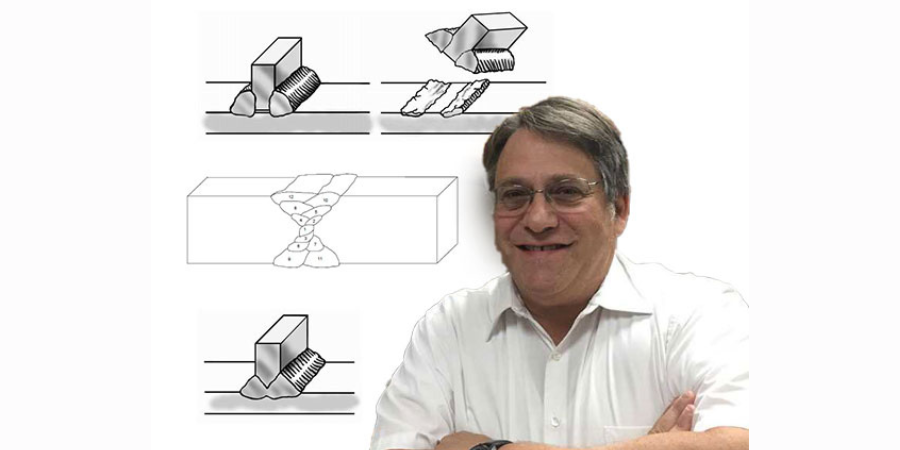
In this Heat Treat TodayTechnical Tuesday feature, Marc Glasser, Director of Metallurgical Services for Rolled Alloys, provides some basic information on the metallurgy as well as good welding practices to follow.
Reprinted with permission from Heat Treat 2019: Proceedings of the 30th Heat Treating Society Conference and Exposition, October 15-17, 2019, Detroit, Michigan, USA. ASM International, 2019.
CHEMISTRY CONSIDERATIONS
Most heat resistant alloys used in the heat treating industry for components are austenitic. They can be austenitic stainless steels, or austenitic nickel alloys. The key word is austenitic. One of the virtues of austenitic materials is that they are not subject of phase changes from cooling to heating or heating to cooling. This is markedly different from alloy and carbon steels, which undergo a phase transformation from austenite to ferrite and cementite. The cooling must be slow enough to prevent martensite formation, so preheating and postheating are performed to either prevent this phase transformation or to temper any formed martensite.
Austenitic alloys do not undergo phase transformations to martensite, and as a result slow cooling the material is the worst operation that an austenitic alloy can be subject to. In austenitic alloys, the main concern is the tendency for welds to hot tear upon solidification[1]. In stainless steels with up to approximately 15% nickel, the solution is simple. The composition is adjusted to form small amounts of ferrite during solidification[2]. Prediction of the ferrite number FN, which represents an estimate of the amount of ferrite in the weld after solidification, is predicted by using Schaeffler diagrams. The ferrite nullifies the effect of certain trace elements that cause hot cracking [1]. One of these trace elements, phosphorous cannot be refined out of the material. Since these materials are all melted from scrap metal, the amount of phosphorous found in the heat will mirror the amount in the scrap. Sulfur, silicion, and boron also contribute to hot shortness, but these elements can be refined to very low levels in the steelmaking process.
For higher nickel bearing grades, with more than 20% nickel, the chemistry precludes the possibility of ferrite formation. Therefore, other means must be employed to prevent hot tearing during solidification. In this case, the residual trace elements, particularly P must be kept low, as they lead to hot shortness [2, 3]. Certain alloy additions including manganese (Mn), niobium (Nb), molybdenum (Mo), and carbon (C) all reduce the propensity of austenitic nickel alloys and high nickel stainless steels to crack [4]. 310 stainless steel stans in a unique position having neither ferrite formers nor weldability-enhancing alloy additions. In this alloy, control of chemistry and residuals is of utmost importance.
The other key to successful welding of nickel alloys is to minimize the time spent in the high temperature range where they are susceptible to hot tearing [4].
GOOD WELDING PRACTICES
Good welding practices for nickel alloys are centered on the need to remove heat as quickly as possible in order to minimize the time spent in the hot tearing range. The first consideration is to keep the heat input as low as possible to still get a full penetration weld. The actual input in kJ is dependent on the alloy being welded.
Heat input (HI) is defined as: HI (KJ/in) = Voltage x Amperage x 6/(Speed (inch/min) x 100)
Welds should NOT be preheated and interpass temperatures should be 200°F maximum. The cooler the interpass temperature is, the less likely hot tearing is [5]. A reliable, easy test for a welder is the spit test. Spit on the weld, and if it boils it is still to hot, and further waiting is in order.
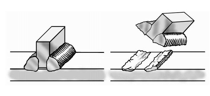
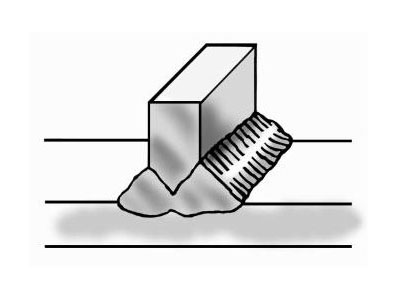
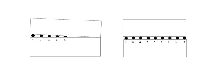
One of the most important considerations in welding nickel alloys is to weld in a straight line along the length of the weld and do not weave. Welders tend to weave from side to side especially when welding nickel alloys which are more viscous that carbon steels and this weaving makes the metal flow better. While this technique works well for carbon steel where a higher heat input and slower cooling are necessary, it is exactly the wrong procedure for nickel alloys. Weaving tends to flatten out a weld. This in turn reduces the crown height and strength.
Furthermore, weaving tends to increase the heat going into the weld and slow down the weld speed. The key is to get a nicely shaped, convex weld bead, as illustrated in Figure 1. A concave bead configuration tends to crack along the centerline [5].
Figure 1: Convex vs. Concave Weld
Full penetration welds are important. Beveling one or more of the pieces to be joined may be required to get a full penetration weld. Incomplete penetration leaves a void between the two workpieces. Such a channel can entrap surface treating gases leading to brittle pieces surrounding the weld. Furthermore, the gap can act as a propagation site for cracks which form from thermal cycling from heat treating. This is shown in Figure 2 below.
Figure 2: The effect of non fully penetrated welds
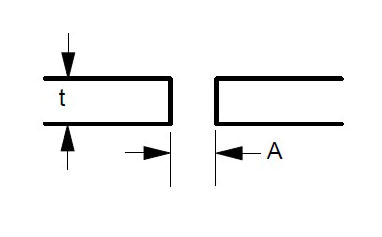
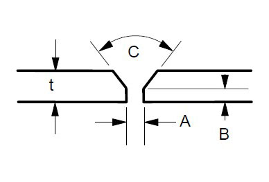
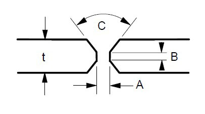
Some suggested joint designs include square butt joint, single V joint, double V joint, single U joint, double U joint, J groove joint, and T Joint. These are shown in Figures 3 to 9 below, along with design criteria. These suggestion grooves are from ASME code[6], but are good guidelines to follow even if code stamps are not required.
Figure 3: Square butt joint. Maximum t = 1/8 ” Gap A = 1/16″ Minimum, 3/32″ Maximum
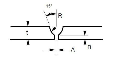
Figure 4: Single V Joint. Maximum t = 1/2″ Gap A = 1/16″ Minimum, 1/8″ Maximum Land B = 1/16 to 3/32″ Angle C = 60 – 75 degrees
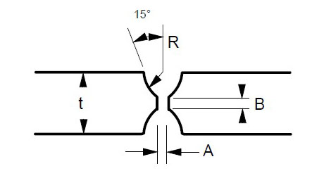
Figure 5: Double V Joint. Gap A = 1/16″ Minimum, 1/8″ Maximum Land B = 1/16 to 3/32″ t = 1/2″ or greater Angle C = 60-75 degrees
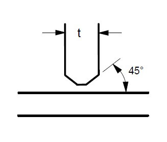
Figure 6: Single U Joint. Gap A = 1/16″ Minimum, 1/8″ Maximum Land B – 1/16 to 3/32″ Radius R – 3/8″ Minimum For single groove welds on heavy plate thicker than 3/4 inch. Reduces the amount of time and filler metal required to complete the weld.
Figure 7: Double U Joint. Gap A = 1/16 to 1/8″ Land B = 1/16 to 3/32″ Radius R = 3/8″ Minimum Minimum t = 3/4″
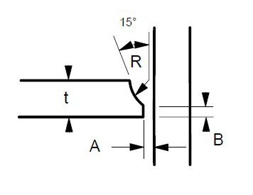
Figure 8: J Groove Joint. Gap A = 1/16 to 1/8″ Land B = 1/16 to 3/32″ Radius R – 3/8″ Minimum For single groove welds on plates thicker than 3/4 inch. Reduces the amount of time and filler metal required to complete the weld.
Figure 9: T Joint. t = greater than 1/4″ For joints requiring maximum penetration. Full penetration welds give maximum strength and avoid potential crevices.
Regardless of which joint is selected, the purpose is to obtain a full penetration weld with no voids or channels, as shown in Figure 10 below.
Figure 10: Example of Full Penetration Weld
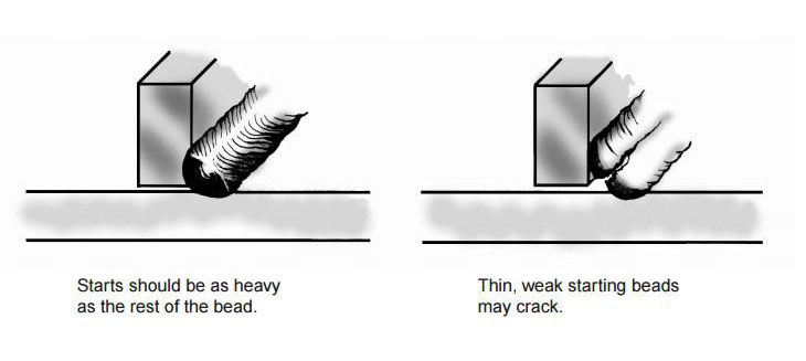
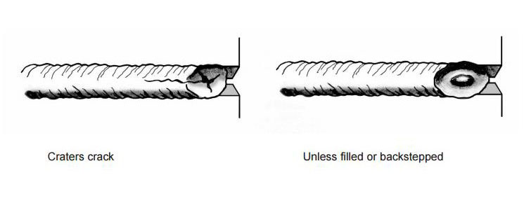
Both the starting and finishing ends of the weld beads can be crack initiation sites. The best practice for starting is to make the start of the weld bead as heavy as the rest of the weld bead [4]. A light or thin start up can cause cracking. This is shown in Figure 11. Furthermore, in nickel alloys, the end of the bead can sometimes yield a star shaped crack. This can be eliminated by backstepping the weld for ½ to 1 inch as shown in Figure 12 [3].
Figure 11: Start welds as heavy as the rest of weld beads
Figure 12: Backstep the weld ends to prevent cracking
Cleanliness is extremely important for welding stainless and nickel alloys. Some general rules include [5]:
Remove all shop dirt, oil, grease, cutting fluids, lubricants, etc. from welding surface and on the area 2 inches wide on each side of the weld joint with suitable cleaning agent.
Eliminate all sources of low melting metal contaminants from paints, markers, dies, back up bars, etc. Chromium plate copper back up bars can form a barrier between copper and the weld surface. Copper can cause HAZ cracking in nickel alloys. These low melting contaminants cause cracking and failures in nickel alloy and stainless steel welds. Avoid using lead or copper hammers in fabrication shops.
Grind clean the surfaces and the HAZ areas. Chromium scales melt at higher temperatures than the base metals and will not be reduced by filler metals.
When welding to nickel alloy or stainless to plain carbon steel, the plain carbon steel must be ground on both sides too.
SHIELDING GASES
Bare wire welding requires a shielding gas to protect the weld from oxidation, loss of some elements to slag or oxide formation, and contamination.
Most stainless steel and nickel alloys require 100% argon for shielding for the GTAW or TIG process.
GMAW or MIG welding has two distinct modes of metal transfer. Spray arc processing transfers metal between wire tip and workpiece as droplets. Short circuit processing transfers the metal in sheets or globules. The most common shielding gas for spray arc GMAW welding is 100% argon. 10-20% helium can be added along with small amounts of carbon dioxide (1% max) to improve bead contour and reduce arc wander [1]. Short circuit GMAW welding uses blends of inert gases usually either 75% argon – 25% helium or 90% helium – 7.5% argon – 2.5% carbon dioxide.
In order to prevent hot cracking with the GMAW process, 602CA® requires a unique blend of 90% argon – 5% helium – 5% nitrogen and a trace (0.05%) carbon dioxide. This blend was trademarked as Linde CRONIGON® Ni30. It is not readily available but there are other close alternate quad gas blends that are commercially available. For GTAW welding, argon with 2.5% nitrogen is used to prevent cracking in 602CA. The nitrogen is the key to preventing cracking in 602CA regardless of method.
RESTRAINT AND DISTORTION CONTROL
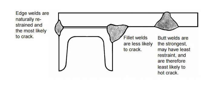
Weld metal shrinks as it freezes. To accommodate the dimensional changes associated with freezing, either the base metal or the weld must move to prevent cracking or tearing. In complex assemblies with multiple welds, each weld, when solidified functions as a stiffener, further restricting movement of subsequent welds. In such cases, the most difficult or crack susceptible weld in the assembly should be made first and the easiest and strongest welds should be made last [5]. An example is shown in Figure 13 below.
Figure 13: Welding with multiple welds. In this example, the edge weld on the left would be the first weld made. The fillet weld in the middle should be the second made, and the butt weld on the right would be the last one made
When multiple tack welds must be made, they should be sequenced along the length of the plate [5]. Tack welding from one end to the other that is made in order will result in plate edges closing up as shown in Figure 14.
Figure 14: Tack welding in order along plate edge (left) can close up and distort the joint. Sequencing the tack welds (right) can greatly reduce distortion
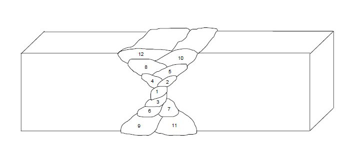
Finally, multipass welds should be sequenced around the center of gravity of the joint as shown in Figure 15 below.
Figure 15: Proper sequencing of multipass welds
REFERENCES
[1] Schaefer, Anton L, Constitution Diagram for Stainless Steel Weld Metal. Metal Progress. ASM, Metals Park, OH. P 680-683. November 1949.
[2] Ogawa T. & Tsunutomi, E. Hot Cracking Susceptibility of Austenitic Stainless Steel. Welding Journal, Welding Research Supplement. P 825-935. March, 1982
[3] Li, L & Messler, R. W. The Effects of Phosphorous and Sulfur on Susceptibility to Weld Hot Cracking in Austenitic Stainless Steels. Welding Journal. Dec. 1999, Vol 78, No. 12.
[4] Kelly J. Heat Resistant Alloys. Art Bookbindery. Winnepeg, Manitoba, Canada. 2013
[5] Kelly J. RA330, Heat Resistant Alloy Fabrication. Rolled Alloys. Temperance, MI. May, 1999
[6] ASME Boiler and Pressure Vessel Code. American Society of Mechanical Engineers. New York, NY. 2013.
A machine tool manufacturer has decided to create their own “captive” heat treat department. The company has consequently invested in two different, yet complementary, vacuum heat treatment furnaces.
The CaseMaster Evolution® multi-chamber vacuum furnace (source: SECO/WARWICK)
As is often the case with companies thinking about how to gain better control of their production systems, one of the obvious bottlenecks for the customer was their offsite heat treatment arrangement. While quality from their existing suppliers was not an issue, it was clear that logistics could certainly be streamlined by eliminating the need to outsource parts to an external heat treater. The furnace manufacturer helped them weigh the pros and cons of moving their heat treatment processes into the plant. Ultimately, a decision was made to set up their own department, invest in new vacuum heat treat equipment, and train their production technicians to perform this critical function of the plant.
SECO/WARWICK received an order for a multi-chamber carburizing vacuum furnace with integral gas or oil quench, and a high pressure gas quench vacuum furnace capable of quench pressures up to 15-Bar.
The Vector® 15-Bar high pressure gas quench vacuum furnace (source: SECO/WARWICK)
“We knew the customer was already getting excellent quality from their supplier, so the question was ‘How can we make the process better?’” said Maciej Korecki, VP of Business Segment Vacuum Heat Treatment Furnaces at SECO/WARWICK. “Starting an in-house heat treat department requires some amount of risk tolerance by ownership, and they needed assurance that the return on production improvements would be worth the investment. [We have] the background to help make those determinations, and as a manufacturer of heat treat equipment, the company was able to offer real-world experience on performance that an independent consultant might not be able to provide.”