Left to Right: Cristóbal Fuentes, CEO of North American Stainless; Bernardo Velázquez, CEO of Acerinox; Matt Bevin, Governor of Kentucky; Rafael Miranda, Acerinox Chairman of the Board
A Ghent, Kentucky, steel production facility recently welcomed a Spanish delegation and state officials to the launch of its 11th expansion since 1990. The project, which was announced in March 2015, includes a new $150 million bright annealing line and a cold rolling mill.
The first set of twin furnaces working on a single pumping station have recently been developed and commissioned to a leading designer and manufacturer of vacuum furnaces for the heat treatment of metal parts.
BMI, a Tenova company, headquartered in Lyon, France, commissioned the B54R-TWIN – vacuum furnaces for tempering – to meet the customer’s specific request for equipment that optimizes energy consumption.
During a heat treatment cycle of the B54R-TWIN, the pumping phase lasts only 30 minutes. Therefore, it is more efficient to use only one pumping group for two furnaces, working alternatively on one furnace or the other. This not only reduces electricity consumption but also minimizes the maintenance costs of the pumps.
Earlier in this quarter, Tenova announced key contracts from Chinese steel producers for six electrical arc furnaces (EAF) Consteel® Evolution in response to Chinese steelmaking industries converting their steel shops plants with EAF technology. In order to improve the reduction rate of CO2 emissions promoted by Chinese government, Chinese steelmakers are starting to increase the share of electrical steel production in comparison to manufacturing using blast or basic oxygen furnaces.
A North American manufacturer of steel products recently announced that construction will begin on two new projects that will boost its capacity to meet demand for carbon and alloy steel products in its U.S. Midwestern and Plains markets.
Nucor Corporation, based in Charlotte, North Carolina, will build a full-range merchant bar quality (MBQ) mill at its existing bar steel mill located in Bourbonnais, Illinois. The MBQ mill will have an annual capacity of 500,000 tons and is expected to cost $180 million. The project will take approximately two years to complete. This project will allow Nucor to fully utilize the company’s existing bar mill by optimizing its melt capacity and infrastructure that is already in place.
In addition, the steel producer will build a rebar micro mill in Sedalia, Missouri, about 90 miles east of Kansas City. The new micro mill project represents at least $250 million in new investments, with the expectation of creating 255 full-time jobs, and anticipates start-up in 2019 pending the final approval and award of state and local incentives as well as required permits and regulatory approvals.
Nucor will be able to take advantage of abundant scrap supply in both locations.
A leading global steel producer recently announced multiple projects as part of a series of planned investments in its UK business. Around £30 million is being earmarked to help secure the future of steelmaking in South Wales, UK.
Tata Steel, headquartered in Mumbai, Maharashtra, India, with steelmaking in the UK and Netherlands, and manufacturing plants across Europe, will replace a Basic Oxygen Steelmaking (BOS) vessel — weighing 500 tonnes – at its Port Talbot site. At the same time, the company is replacing the massive cranes in the steel plant and installing enhanced dust extraction hoods and energy-efficient drives to minimize emissions.
The 11-meter high BOS vessel is a steel cauldron used to convert iron into steel before it is further processed and delivered to customers making products like cars, innovative packaging, and energy-efficient buildings.
Earlier this year Tata Steel unveiled the UK’s most advanced robotic steel welding line which supplies material for car makers from its site in Wednesfield, UK.
Port Talbot produces high-quality steel which is further processed at Tata Steel’s steel mills around the UK for manufacturers in Britain, mainland Europe and other countries around the world. Once installed, the new steelmaking vessel will be able to convert 330 tonnes of iron into steel in each cycle. This is done by pumping oxygen through liquid iron at twice the speed of sound, removing unwanted carbon and allowing employees to produce critical grades of steel.
“We have two steelmaking vessels and they run 24/7 at temperatures of up to 1,700C, apart from short planned maintenance periods. Despite this, they last for around 20 years each and replacing them is an important part of ensuring reliable operations,” said Dave Murray, Project Manager.
Scientists at several research institutions recently reported a breakthrough in 3D printing a marine grade stainless steel — a low-carbon type called 316L — that promises high-strength and high-ductility properties. Researchers at Lawrence Livermore National Laboratory (LLNL), along with collaborators at Ames National Laboratory, Georgia Tech University, and Oregon State University, published their findings online October 30, 2017, in the journal Nature Materials.
LLNL scientist Morris Wang (left) and postdoc researcher Thomas Voisin played key roles in a collaboration that successfully 3D printed one of the most common forms of marine grade stainless steel that promises to break through the strength-ductility tradeoff barrier.
“Marine grade” stainless steel is valued for its performance under corrosive environments and for its high ductility — the ability to bend without breaking under stress — making it a preferred choice for oil pipelines, welding, kitchen utensils, chemical equipment, medical implants, engine parts and nuclear waste storage. However, conventional techniques for strengthening this class of stainless steels typically comes at the expense of ductility.
“In order to make all the components you’re trying to print useful, you need to have this material property at least the same as those made by traditional metallurgy,” said LLNL materials scientist and lead author Morris Wang. “We were able to 3D print real components in the lab with 316L stainless steel, and the material’s performance was actually better than those made with the traditional approach. That’s really a big jump. It makes additive manufacturing very attractive and fills a major gap.”
Wang said the methodology could open the floodgates to widespread 3D printing of such stainless steel components, particularly in the aerospace, automotive, and oil and gas industries, where strong and tough materials are needed to tolerate extreme force in harsh environments.
To successfully meet, and exceed, the necessary performance requirements for 316L stainless steel, researchers first had to overcome the porosity which causes parts to degrade and fracture easily during the laser melting (or fusion) of metal powders. Researchers addressed this through a density optimization process involving experiments and computer modeling, and by manipulating the materials’ underlying microstructure.
Researchers say the ability to 3D print marine grade, low-carbon stainless steel (316L) could have widespread implications for industries such as aerospace, automotive, and oil and gas.
“This microstructure we developed breaks the traditional strength-ductility tradeoff barrier,” Wang said. “For steel, you want to make it stronger, but you lose ductility essentially; you can’t have both. But with 3D printing, we’re able to move this boundary beyond the current tradeoff.”
Using two different laser powder bed fusion machines, researchers printed thin plates of stainless steel 316L for mechanical testing. The laser melting technique inherently resulted in hierarchical cell-like structures that could be tuned to alter the mechanical properties, researchers said.
Wang called stainless steel a “surrogate material” system that could be used for other types of metals. The eventual goal, he said, is to use high-performance computing to validate and predict future performance of stainless steel, using models to control the underlying microstructure and discover how to make high-performance steels, including the corrosion-resistance. Researchers will then look at employing a similar strategy with other lighter weight alloys that are more brittle and prone to cracking.
“We didn’t set out to make something better than traditional manufacturing; it just worked out that way,” said LLNL scientist Alex Hamza, who oversaw production of some additively manufactured components.
In addition to organic expansion in the U.S. and Asia automotive and construction sectors, Hindalco Industries recently revealed an interest in aluminum processing in aerospace, defense, and high-speed rail industries, according to a recent interview with Hindalco’s MD Satish Pai, published in The Economic Times.
LEAX Group, a Swedish manufacturer of advanced components and subsystems for automotive, commercial vehicles, mining, construction, and general industry sectors, has installed a low pressure carburizing (LPC) furnace at their Brinkmann, Germany, facility (LEAX Brinkmann GmbH) to boost the company’s heat treatment processing capabilities. The extensive installation takes about two months and the first hot load is scheduled for December. Along with the addition of a new induction machine at their Falköping, Sweden, facility, this new LPC furnace serves as the centerpiece of the massive MBS project.
LEAX, which is based in Köping, Sweden, operates heat treatment shops in seven of their twelve production sites, including Latvia, Germany, Hungary, Brazil, and China, and focuses on induction hardening and processing and refining approximately 300,000 parts per year. This added LPC hardening furnace brings a process to LEAX’s manufacturing process that has been a mainstay in the automotive industry. The full transition to the MBS project will take up to two years, but “we [will] switch hardening from the older oven to the new,” said Anders G. Larsson, COO/Heat Treatment for LEAX Brinkmann GmbH.
Here is what readers are saying about recent posts on Heat Treat Today. Submit your comments to editor@heattreattoday.com.
Jason Schulze, contributing editor to Heat Treat Today, author of "AMS2750E: The Importance of Temperature Uniformity"
Joe Powell, President, Intensive Quench Technologies, on Jason Schulze's article, "AMS2750E: The Importance of Temperature Uniformity" (click here to see original article):
Interesting to me how big a deal specs make on temperature uniformity in the hot zones, and how little attention is paid to quantifying the uniformity of the quench cooling process! But we all know predictable distortion and uniformity of mechanical properties can only happen when the quench cooling is uniform!
Bill Jones, CEO Solar Atmosphere, on Jason Schulze's article, "AMS2750E: The Importance of Temperature Uniformity" (click here to see original article):
Let us assume a standard box furnace air atmosphere operating at 1650f with a plus-minus 25f delta T. What first areas would you recommend to look for improvement.
When I had issues achieving uniformity, I typically focus on the position of the control thermocouple 1st, then work my way to other items.
From the article "Jason Schulze on AMS2750E: The Importance of Temperature Uniformity"
Bill Jones:
AMS 2750, etc, is fine for setting specification and procedure. In some cases unreasonable and meaningless in operation, for example, a 1-degree overshoot on ramp rate by a control TC can result in a major NADCAP finding even though work TC's are well below set point. Okay, so we do a TUS and it fails, so now you have to locate and solve the furnace problem or very possibly mis-survey TC placement. Now, I don't recommend changing control TC placement away from factory location or position at all. The OEM is supposed to run a full TUS survey prior to shipment in his plant. In other words, go back to those locations before introducing new problems. Now, a furnace may be 5 or 10 years in service with many HZ "aging" problems. These issues must be located and addressed. Another major fault is TC survey plugs, jacks, and deteriorated wiring all leading to measurement error and survey failure. This entire TUS subject is an art with many pitfalls with not too many really experienced technicians.
Jason Schulze for HTT:
I do agree that there are aspects of some requirements that do not actually affect production processing. Since my experience is metallurgical, that is where my examples would reside.
We welcome your inquiries to and feedback on Heat TreatToday articles. Submit your questions/comments to editor@heattreattoday.com.
An international manufacturer of industrial furnaces, ovens, ceramic kilns, and combustion systems, based in Monterrey, Mexico, recently announced the key asset acquisition of a Pennsylvania-based supplier of industrial furnace and process-heat treating equipment, broadening its offerings to the steel, aluminum, and alloy industries, and ultimately user industries such as steel, heat treatment, aerospace, automotive, and oil and gas.
Nutec Bickley expands its operations by bringing on board Olson Industries’ line of equipment to secure access to larger projects for the Metals Business Unit and consolidating its position in the North American market. As part of the transaction, Bryan Kraus (President and Owner of Olson Industries), will be engaged in Nutec Bickley’s Metals BU, providing guidance and assistance in related activities such as technical sales and engineering.
“We are very excited about Olson Industries and Bryan Kraus joining the Nutec Bickley family,” said Nutec Bickley President, Daniel Llaguno. “Applications such as large rotary-hearth furnaces, and peripheral equipment such as quenching systems, manipulators, robots, and conveyors will now be a standard offering from us,” confirmed Daniel Llaguno. “If you couple that with Nutec Bickley’s state-of-the-art facilities, highly experienced staff, and constant focus on customer satisfaction, you can see that there is indeed a very powerful value proposition on offer to both existing and new customers.”
Induction Hardening Tips: Equipment Selection for Scan Hardening
Introduction
Induction scan hardening is one of the more popular techniques for strengthening various steels, cast irons, and powder metallurgy components. This scanning method is be used to harden flat surfaces or irregular shapes (e.g., rails, bumpers, bed-ways, support beams, track shoes for earth moving machines, teeth of large gears, etc.); however, it is most frequently used for hardening outside and/or inside surfaces of cylindrically shaped components, such as shafts, pins, raceways, etc. In scan hardening, the inductor or workpiece or both moves linearly relative to each other during the hardening cycle.
Depending on the workflow of parts, the induction system can be built as vertical, horizontal, or even at an angle, though vertical scan hardening is by far the most popular design. As an example, Figure 1 shows three variations of the InductoScan® family of modular vertical scan hardening systems.
Figure 1. Variations of the InductoScan® family of vertical modular scan hardening systems. (Courtesy of Inductoheat, Inc.)
What to Choose: Vertical Scanners vs. Horizontal Scanners
Both vertical and horizontal induction scanning systems are viable means to heat treat components. The decision of whether to use a vertical or horizontal scan hardening system is usually based upon the shape and length of heat treated parts, as well as the available space and a workflow throughout the plant or factory in which the equipment is to be installed. Horizontal hardening is often chosen when long workpieces are to be processed (typically 4ft/1.2m or longer) or when high production rates are needed for processing shorter parts.
Vertical scanners are typically associated with a smaller footprint. In the majority of applications, the cylinder-shaped workpiece (e.g., shafts) is positioned between centers or some other tooling or fixture. The workpiece may rotate inside the inductor to even out the hardening pattern around the circumference, or it may be located preferentially with respect to the inductor and processed without rotation when hardening workpieces of certain shapes. The quench spray typically impinges the part approximately 12mm (½”) to 40mm (1.5”) from the coil heating face and is angled away to prevent the quench from splashing back into the inductor. This dimension can vary with different types of steel, the scan rates, and the design specifics.
Setting Up Scan Hardening Systems
Vertical systems can be set up to process as many as four shafts at a time depending on the size of the shafts being processed and the available power source. Parts are loaded either manually or automatically onto a lower center. A loading assist “vee” block or nest may be used to steady the part as it is being loaded and processed. For larger parts, pneumatic cylinders lift the upper centers to facilitate loading. With vertical scan hardening, it may take an appreciable amount of time to process the workpiece because it must be loaded, scanned along the length up to the position where the heating process commences, fast scanned back down to the load-unload position, and then unloaded.
In contrast, a horizontal system is typically set up as a single continuous scanning line that allows parts to be loaded from a magazine and continuously fed to the exit of the machine. Depending on the specific heating requirements for the end of the component, parts are fed end-to-end through the heating coil and pass on to the next process. The loading system can push parts through the inductor by a pinch drive mechanism, conveyor, mechanical pushers, or other means, such as skewed rollers [1]. On a horizontal system, due to heavy duty roller support underneath, gravity, and any required stabilizing devices on top of the workpiece, the part is maintained in the center of the induction coil and quench ring. There is usually less risk of distortion than that which occurs with a vertical system where the part’s shape can change or warp if the part is not always centered.
However, during the heating process on a horizontal system, it may be more difficult to maintain the exact location of features of the part since it is commonly free rolling on the skewed rollers. For this reason, consideration should be given to a part’s shape, the symmetry of its positioning in respect to the heating coil, and selection of support devices. When horizontal systems are used for heat treating long parts of appreciable weight, it might be challenging to speed up or slow down the progress of the workpiece along the skewed rollers as quickly as might be done in vertical scanners with a servo-driven carriage that captures the part.
The roller system of horizontal scan hardeners can interfere with achieving symmetrical cooling of the workpiece since the location of the rollers and the rotation detection mechanism on shorter parts may be too close to the coil or quench barrel. Additionally, a stabilizing fixture may be required to prevent lighter and smaller workpieces from being moved axially by electromagnetic forces rather than the roller system. As with the vertical system, some type of rotation detection must be employed to ensure that the part is actually rotating as it is passing through the heating coil.
Quenching Challenges
Quenching presents a challenge with horizontal scanning [1]. When scanning vertically, quenching takes place below the inductor, which naturally allows gravity to pull the quench fluid down, therefore, the quench fluid continues to flow on the part long after it has passed the quench chamber, which is beneficial to achieving circumferential uniformity of quenching as well as reaching temperatures suitable for handling. When quenching horizontally, the effect of gravity is different and the way the quenchant falls from the workpiece varies leading to the probability of non-uniform cooling along the circumference of the heat-treated component (e.g., quenchant may run along the top of the part but fall off the bottom).
It is also more critical for horizontal scanners to maintain a sufficient distance between the inductor exit and the quenching device due to the higher probability of the liquid quenchant splashing back into the inductor. This could lead to irregular results caused by different cooling rates affecting the hardness consistency as well as the magnitude and distribution of residual stresses.
All of these factors can be summarized as follows:
The main process differences between vertical or horizontal scan hardening systems lie in the part handling and quenching subtleties.
With some scanners, splash shields, deflectors, and drip trays may be needed to prevent the backsplash of the quench fluids.
Maximizing Process Flexibility of Induction Scanners
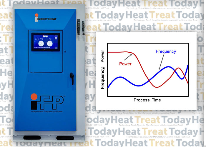
It is commonly assumed that all scan hardening systems exhibit high process flexibility with respect to the workpiece length and, to some extent, variations in the diameter of the part. Conventional scan hardening provides the ability to vary the speed and power during the process, which controls the amount of heat applied to different areas of the part. Recently developed Statipower-IFP® inverter technology (Figure 2) extends the capability of conventional induction hardening systems to instantly and independently adjust not only power and scan rate but also frequency (5kHz to 60kHz range) during scan hardening cycle [2].
Figure 2. Statipower-IFP® inverter allows instant and independent adjustment of frequency (5kHz to 60kHz) and power during scan hardening cycle. (Courtesy of Inductoheat Inc.).
In the past, the flexibility of induction scanners was limited to using power supplies with single operational frequency. However, when processing a family of parts or components with numerous geometrical irregularities (including large diameter changes, multiple holes, sharp shoulders, combinations of solid and hollow areas, various required case depths, etc., see Figure 3), the fixed frequency in conventional induction scanners can be inadequate, producing “hot” and “cold” spots, as well as unwanted microstructures (e.g., local grain boundary liquation and grain coarsening).
Figure 3. A family of components exhibiting numerous geometrical irregularities
Single frequency scanners have been used to tweak the process in an attempt to promote or suppress thermal conduction [1,2], resulting in a compromise in achieving the desired metallurgical quality, production rate, and process capability. In the heating stage, compromise affects the ability to provide heat-appropriate austenization, but it also presents challenges in the quenching stage.
Austenization is followed by a quenching stage (spray or immersion). If the available, fixed frequency of a conventionally designed induction scanner is considerably higher than optimal then the depth of heat it generates (current penetration depth) is smaller than needed, which might not be sufficient in establishing necessary austenization. In this case, to reach sufficient austenization, the scan rate and applied power must be reduced to allow thermal conduction to the required subsurface depth. Unfortunately, a noticeable heat surplus might still occur.
An Example of Compromised Results
As an example, Figure 4 shows the computer modeling results of the induction scan hardening of a hollow medium carbon steel shaft that has diameter changes, a chamfer, and a groove. Nominal outside diameter is 0.05m (2”); nominal inside diameter is 0.02m (3/4”). Because the shaft is symmetrical, only the top half was modeled. Temperature variations at four selected areas of the shaft are monitored at different inductor positions. Frequency was constant at 15 kHz.
The scan rate and coil power were varied during hardening as an attempt to accommodate changes in the shape of the shaft.
Reducing scan speed (in some cases substantially) not only adds unnecessary cycle time, but if the scan speed is too slow, certain regions of a heat-treated component may cool below the critical temperature before it enters the quench zone, resulting in an undesirable formation of mixed structures and upper transformation products, as well as reduced or spotty hardness readings.
If the fixed frequency of a conventionally designed scanner is noticeably lower than optimal, it may produce a deeper than required austenized layer, affecting hardness depth, transition zone and creating excessive distortion. In this case, increasing scan rate and power density should minimize, but not eliminate, this outcome. Such a compromise can still affect local spray quenching producing undesirable metallurgical results.
Conclusion
It is important to remember that applied frequency has the greatest impact on depth of induction heat generation. A new generation of Statipower-IFP® inverters (Figure 2) eliminates these drawbacks by optimizing the metallurgical quality of induction scan hardening, expanding process flexibility and maximizing a production rate. This patented technology can be effectively used in both vertical and horizontal induction scanners. Reports [2] show changing both coil power and frequency during scan hardening can reduce peak temperatures on 70oC (125oF) while maintaining the required hardness pattern.
I recommend Reference #1 to readers interested in further discussion on induction scan hardening subtleties.
Doyon, V.Rudnev, C.Russell, J.Maher, Revolution-not evaluation-necessary to advance induction heat treating, Advance Materials & Processes, September 2017, p.72-80.
______________________________________________
Dr. Valery Rudnev, FASM, is the Director of Science & Technology, Inductoheat Inc., and a co-author of Handbook of Induction Heating (2nd ed.), along with Don Loveless and Raymond L. Cook. The Handbook of Induction Heating, 2nd ed., is published by CRC Press. For more information click here.