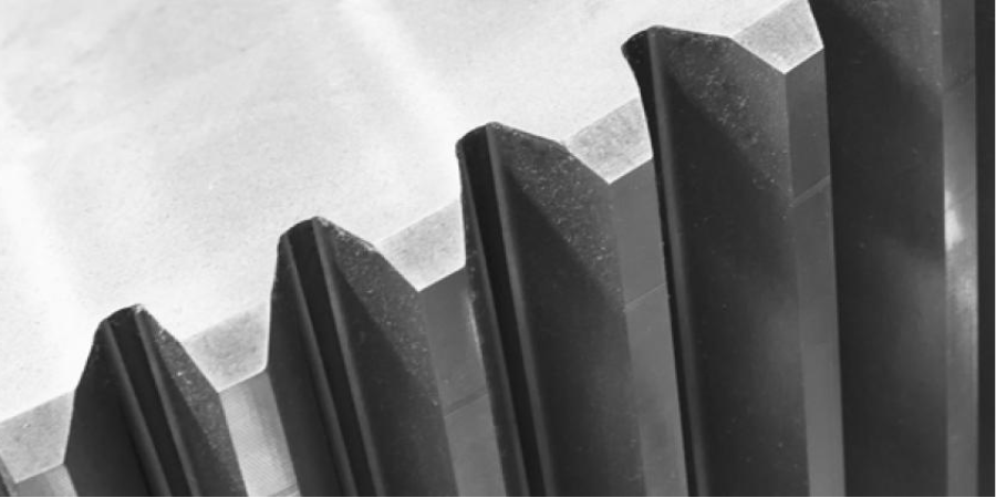
Case Study: Heat Treat Equipment Meets the Future Industry Today
![]() Modern industry trends and expectations pose new challenges to heat treating equipment; in addition to the expected requirements (e.g., safety, quality, economy, reliability, and efficiency), factors like availability, flexibility, energy efficiency, environmental, and the surrounding carbon neutrality are becoming increasingly important.
Modern industry trends and expectations pose new challenges to heat treating equipment; in addition to the expected requirements (e.g., safety, quality, economy, reliability, and efficiency), factors like availability, flexibility, energy efficiency, environmental, and the surrounding carbon neutrality are becoming increasingly important.
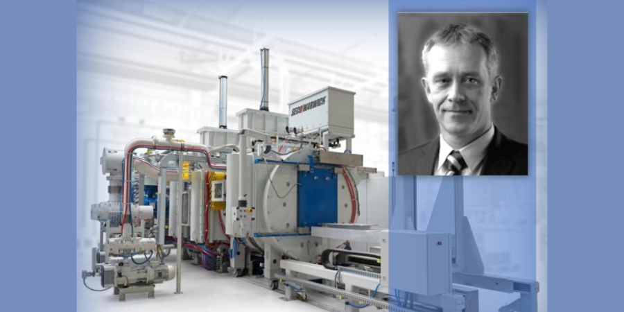
Maciej Korecki, vice president of Business Development and R&D at SECO/WARWICK, presents this special Technical Wednesday case study for the last day of FNA 2022 to focus on an equipment solution that meets these modern industry demands: a semi-continuous vacuum furnace for low-pressure carburizing (LPC) and high-pressure gas quenching (HPGQ).

Vice President of Business of the Vacuum Furnace Segment
SECO/WARWICK
Introduction
At least 60 years ago, vacuum furnaces first appeared in the most demanding industries (i.e., space and aerospace), then spread to other industrial branches, and are now widely implemented in both mass production and service plants. Use of vacuum technology does not look like it is slowing down anytime soon.

The driving forces behind this growth in vacuum technology are two-fold: first, the increasing heat treatment requirements that result from the directions of industrial development and production systems, and second, environmental protection, where the advantages of vacuum technologies are undeniable.
Traditional Atmospheric Technology
Case hardening by carburizing is one of the most widely used heat treatment technologies. It consists in carburizing (introducing carbon to the surface) followed by quenching of the carburized layer. Typically, the work is carburized in a mixture of flammable gases (CO, H2), and quenched in oil in an atmosphere furnace, using methods developed in the 1960s.
These methods have a history of development, though the question remains if the technological developments can keep up with the requirements of modern industry. Safety is an issue with this method due to the use of flammable (and poisonous) gases and flammable oil, as well as open flame, which in the absence of complete separation from the air can lead to fire, or poisoning.
In addition, they affect their environment by releasing significant amounts of heat, polluting the surroundings with quenching oil and its vapors. They require the use of washers and cleaning chemicals, emit annually tens or even hundreds of tons of CO2 (greenhouse gas, the main culprit of global warming and dynamic climate change) coming from the carburizing atmosphere, and for these reasons, they need to be installed in dedicated so-called “dirty halls” separated from other production departments.
The resulting requirement to limit the temperature of the processes to 1688-1706 oF (920-930oC) is also not without importance, as it blocks the possibility of accelerating carburization and increasing production efficiency (due to the use of metal alloys in the construction, the service life of which drops dramatically at higher temperatures) and the formation of unfavorable intergranular oxidation (IGO), which is a characteristic feature of the atmospheric carburizing method.
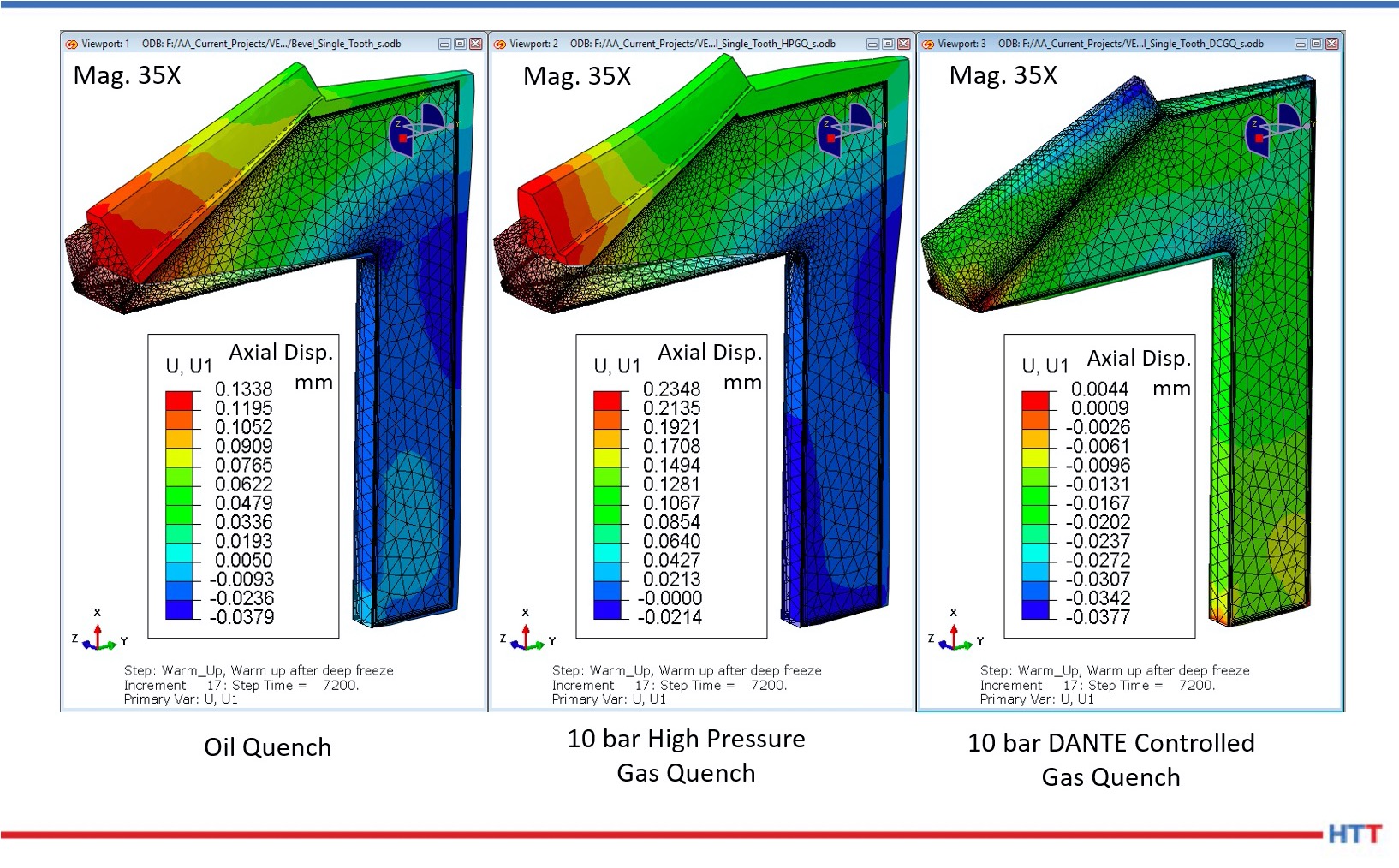
Quenching in oil is effective, but it does not have precise controllable, repeatable, and ecological features that heat treaters may need. Due to the multiphase nature of oil quenching (steam, bubble, and convection phase) and the associated extremely different cooling rates, it is characterized by large and unpredictable deformations within a single part and the entire load. Furthermore, there is no practical method to influence and control the quench process.
Modern Vacuum Technology with LPC and HPGQ
Vacuum carburizing appeared as early as the 1970s, but it could not break through for a long time due to the inability to control and predict the results of the process, and heavy contamination of the furnaces with reaction products.
The breakthrough came in the 1990s, when acetylene began to be used as a carbon-bearing gas and computers were employed to control and simulate the process. Since the beginning of the 21st century, there has been a rapid development of the low pressure carburizing (LPC) technology and an increase in its industrial demand, which continues today with an upturn.
Vacuum carburizing occurs with the aid of hydrocarbons (usually acetylene), which catalytically decompose at the surface, providing carbon that diffuses into the material. The process is carried out under negative pressure (hundreds of times less than atmospheric pressure) and is very precise, efficient, and uniform due to the very high velocity and penetration capacity of the gas molecules, allowing the carburizing of large and densely packed loads and hard-to-reach surfaces such as holes.
In addition, the use of non-oxygen-containing hydrocarbon atoms eliminates the qualitative problem of intergranular oxidation (IGO). The process is completely safe, there is no flammable or poisonous atmosphere in the furnace and no open flame, and the furnace can work unattended and is fully available and flexible, i.e., it can be turned on and off on demand, which does not require any preparation. Similarly, changing the carburizing parameters takes place efficiently.
Due to the design of the vacuum furnace and the use of materials with high resistance to temperature, i.e., graphite — the only limitation for the temperature of the carburizing process is the steel from which the parts are made — it is possible to carburize at higher temperatures than traditional methods allow. The result is a significantly shorter carburizing time and increased furnace efficiency versus what can be achieved in an atmosphere furnace.
Neutral gas cooling was included with the vacuum furnaces. Initially, engineers used a cooling gas (nitrogen or argon) at near ambient pressure and natural convection. Subsequent solutions introduced fan-forced gas flow in a closed circuit. The cooling efficiency under such conditions was hundreds of times lower compared to that of oil, allowing only high-alloy steels and parts with very limited cross-sections to be hardened. Over the following decades, the development of HPGQ was focused on improving cooling efficiency by increasing pressure and velocity and using different types of gas and their mixtures. Current systems have cooling efficiencies on a par with oil-based systems and enable the same types of steel and parts to be hardened, with the advantage that deformation can be greatly reduced and reproducible, and the process is completely controllable (through pressure and gas velocity) allowing any cooling curve to be executed.
Vacuum technologies have an ecological edge. Because of their design and processes, vacuum furnaces do not interfere with the immediate surroundings and are environmentally friendly, so they can be installed in clean halls, directly in the production chain (in-line). They emit negligible amounts of heat and post-process gases which are not poisonous and contain no CO 2 at all. Gas quenching eliminates harmful quenching oil and the associated risk of fire and contamination of the immediate environment, as well as the need for equipment and chemicals for its removal and neutralization. Nitrogen used for cooling is obtained from the air and returned to it in a clean state, creating an ideal environmentally friendly solution.
The presented advantages of vacuum technologies influence its dynamic development and increase the demand of modern industry, and the gradual replacement of atmospheric technologies.
Vacuum furnaces are available in virtually any configuration: horizontal, vertical, single, double, or multi-chambered, tailored to the process and production requirements. In light of recent global changes, requirements, and industrial trends, special attention should be paid to disposable, flexible, and rapidly variable production and process systems, as well as independent and autonomous systems, which include a three-chamber vacuum furnace for semi- continuous heat treatment, equipped with LPC and HPGQ.
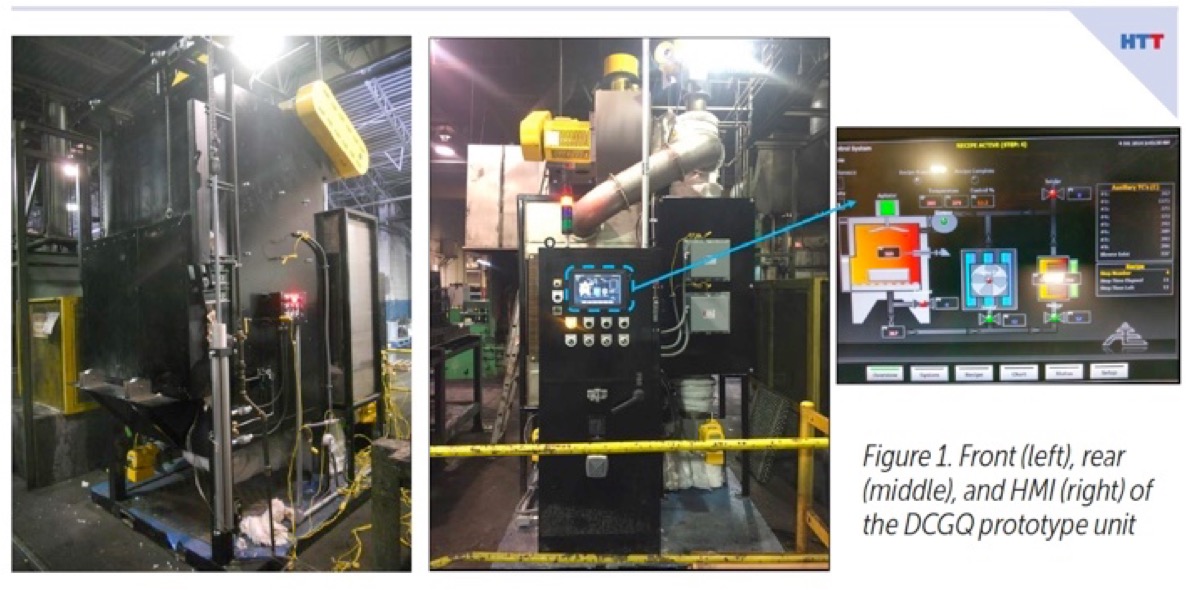
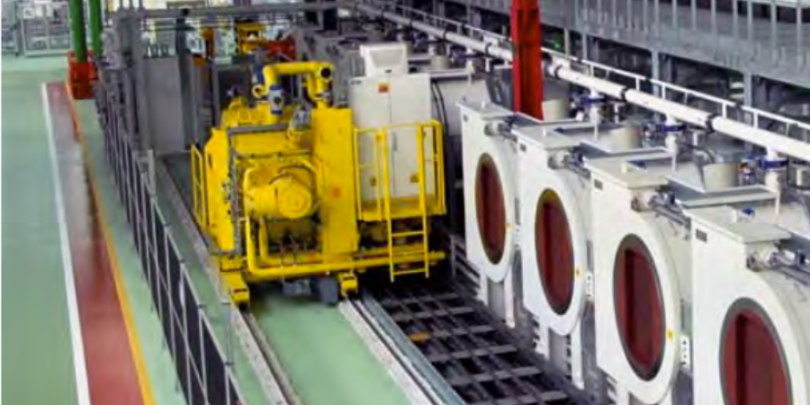
Three-Chamber Vacuum Furnace — CaseMaster Evolution Type CMe-T6810-25
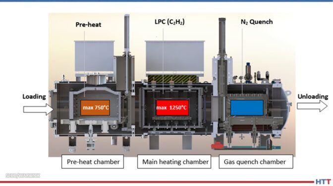
This is a compact, versatile, and flexible system designed for vacuum heat treatment processes for in-house and commercial plants, dedicated to fast-changing and demanding conditions in large-scale and individual production (Fig. 1). It enables the implementation of case hardening by LPC and HPGQ processes and quenching of typical types of oil and gas hardened steels and allows for annealing and brazing. It is characterized by the following data:
- working space 610x750x1000 mm (WxHxL)
- load capacity 1000 kg gross
- temperature 2282oF (1250oC)
- vacuum range 10-2 mbar
- cooling pressure 25 bar abs
- LPC acetylene gas
- Installation area 8x7m
The furnace is built with three thermally and pressure-separated chambers (Fig. 2.), and operates in a pass-through mode, loaded on one side and unloaded on the other, simultaneously processing three loads, hence its high efficiency. The load is put into the pre-heating chamber, where it is pre-heated to the temperature of 1382oF (750oC), depending on the requirements: in air (pre-oxidation), nitrogen or vacuum atmosphere. It is then transferred to the main heating chamber, where it reaches process temperature and where the process is carried out (e.g., LPC).
In the next step, the charge is transported to the quenching chamber, where it is quenched in nitrogen under high pressure. All operations are automatic and synchronized without the need for operator intervention or supervision.
Source: SECO/WARWICK
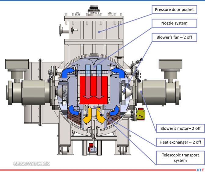
Particularly noteworthy is the gas cooling chamber, which in nitrogen (rather than helium) achieves cooling efficiencies comparable to oil (heat transfer coefficient >> 1000 W/m2K), thanks to the use of 25 bar abs pressure and hurricane gas velocities in a highly efficient closed loop system. The cooling system is based on two side-mounted fans with a capacity of 220 kW each, forcing with nozzles an intensive cooling nitrogen flow from above onto the load, then through the heat exchanger (gas-water), where the nitrogen is cooled and further sucked in by the fan (Fig. 3). The cooling process is controllable, repeatable, and programmable by gas pressure, fan speed and time. An intense and even cooling is achieved. The result is the achievement of appropriate mechanical properties of parts with minimal hardening deformations, without the use of environmentally unfriendly oil or very expensive helium.
Source: SECO/WARWICK
An integral part of the furnace system is the SimVaC carburizing process simulator, which enables the design of furnace recipes without conducting proof tests.
Distinctive Features of the CMe-T6810-25 Furnace
The advantages of this type of furnace — versus more traditional or past forms — can be demonstrated in a number of usability and functional aspects, the most important of which are the following:
Safety:
- Safe, no flammable and poisonous atmosphere
- No open fire
Production and installation:
- Intended for high volume production (two to three times higher output when compared to single- and double-chamber furnaces)
- Effective and efficient LPC (even five times faster than traditional carburizing)
- Total process automation & integration
- Clean room installation
- Operator-free
- Compact footprint
Quality:
- High precision and repeatability of results
- Uniform carburizing of densely pack loads and difficult shapes (holes)
- No decarburization or oxidation
- Elimination of IGO
- Ideal protection and cleanliness of part surfaces
- Accurate and precise LPC process simulator (SimVaC)
Quenching:
- Powerful nitrogen quenching (neither oil nor helium is needed)
- Reduction of distortion
- Elimination of quenching oil and contamination
- Elimination of washing and cleaning chemicals
Operational:
- Flexible, on-demand operation
- No conditioning time
- No human involvement and impact
- High lifespan of hot zone components — i.e., graphite
- No moving components in the process chamber
Ecology:
- Safe and environmentally friendly processes and equipment
- No emission of harmful gases (CO, NOx, SOx)
- No emission of climate-warming gas CO2
Based on the CMe-T6810-25 furnace performance, it is rational and reasonable to build heat treatment systems for high-efficiency and developmental production in a distributed system by multiplying and integrating further autonomous and independent units. The reasons for doing so are because the furnace design affords:
- No risk of production total breakdown
- Unlimited operational flexibility
- Less initial investment cost
- Unlimited multiplication
- No downtime while expansion
- Independent quenching chamber
- Independent transportation
- Independent control system
The characteristics, capabilities and functionalities of the CMe-T6810-25 furnace fit very well with the current and developmental expectations of modern industry and ecological requirements, which is confirmed by specific implementation cases.
Case Study
The three-chamber CaseMaster Evolution CMe-T6810-25 vacuum furnace was installed and implemented for production at the commercial heat treatment plant at the Polish branch of the renowned Aalberts surface technologies Group in 2020.
Source: SECO/WARWICK
The CMe furnace, together with the washer and tempering furnace, forms the core of the department's production, which is why the furnace is operated continuously. Last year, the furnace performed over 2000 processes and showed very high quality (100%) and reliability (> 99%) indicators. The very high efficiency of the furnace was also confirmed, which, with relatively low production costs, contributes to a very good economic result.
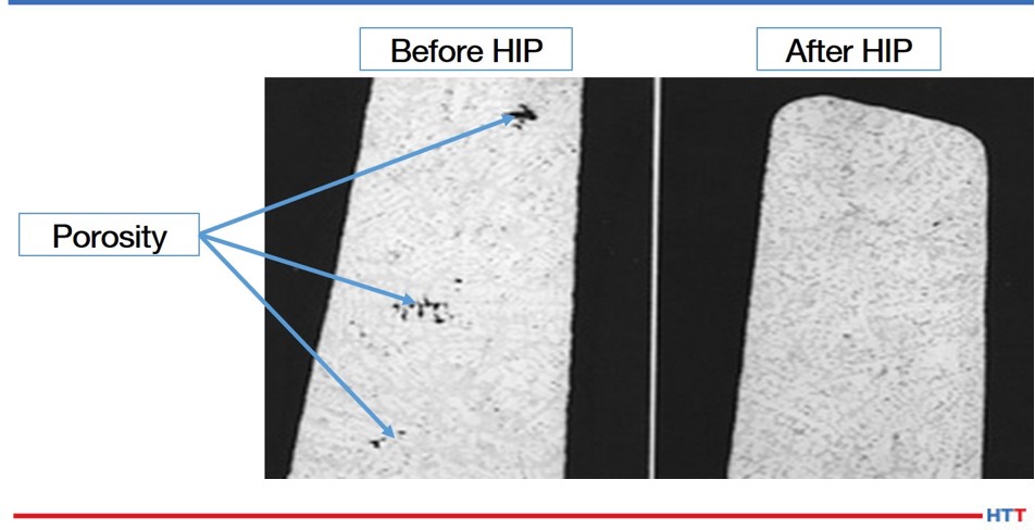
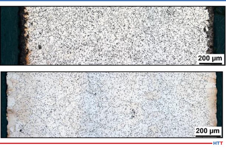
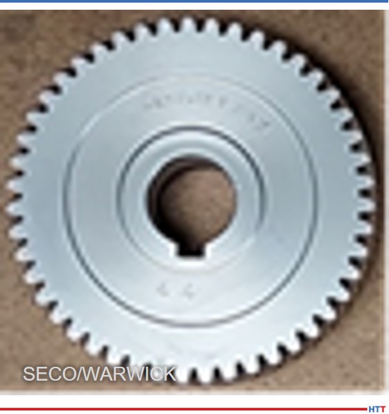
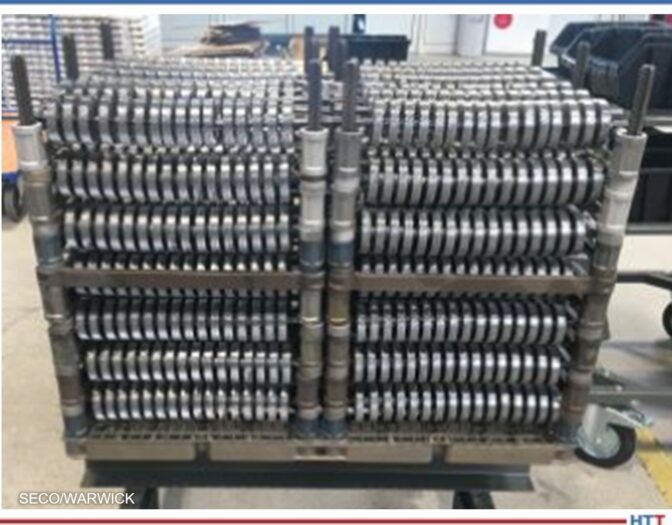
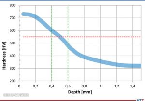
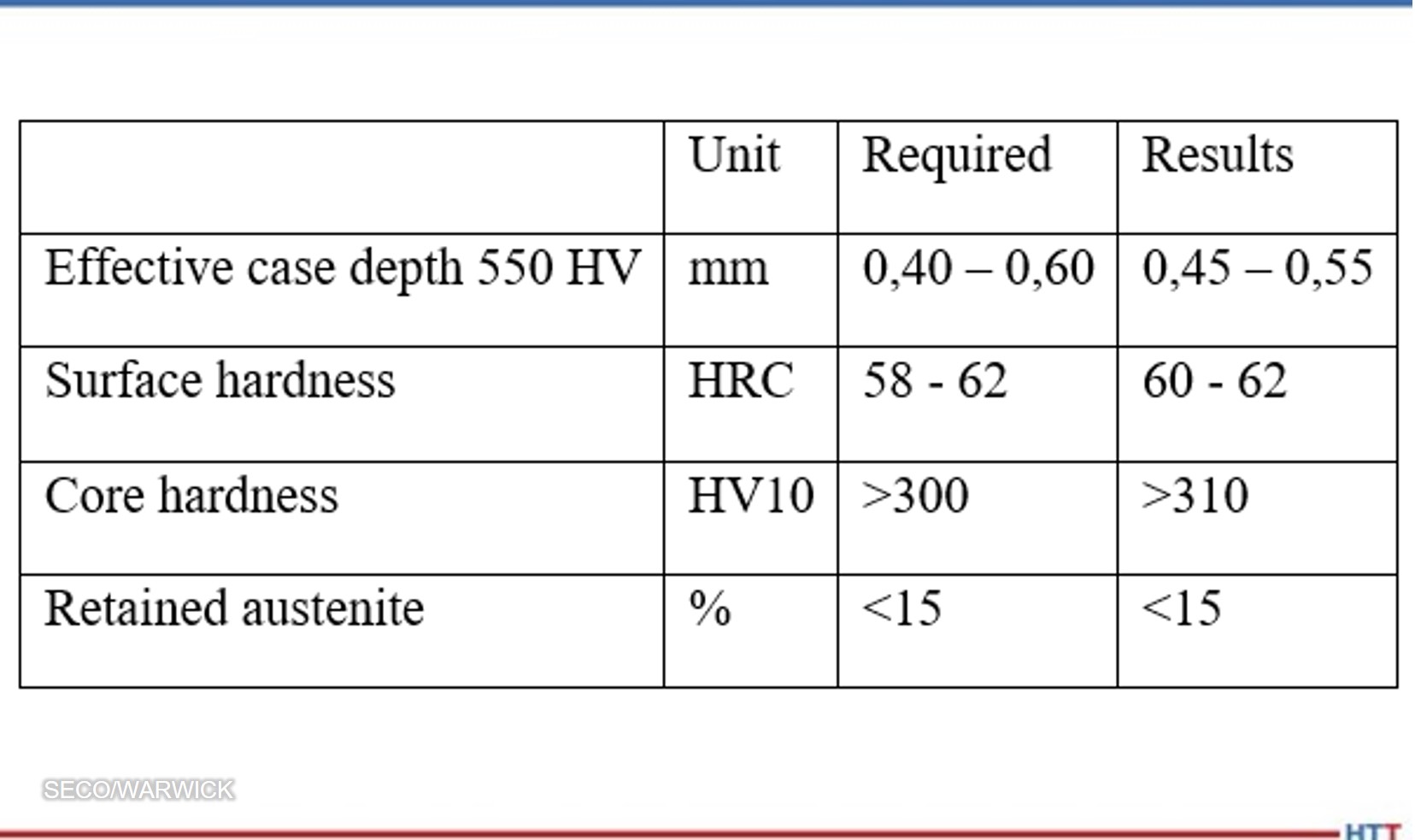
The case hardening process on gearwheels used in industrial gearboxes was taken as an example. The wheel had an outer diameter of about 80 mm and a mass of 0.52 kg (Fig. 4), and the load consisted of 1344 pieces densely packed in the working space (Fig. 5) with a total net weight of 700 kg (920 kg gross) and 25 m2 surface to be carburized. The aim of the process was to obtain an effective layer thickness from 0.4 – 0.6 mm with the criterion of 550 HV, surface hardness from 58 – 62 HRC (Rockwell Hardness C), core hardness at the gear tooth base above 300 HV10 and the correct structure with retained austenite below 15%.
Source: SECO/WARWICK
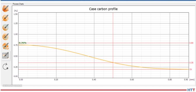
The LPC process was designed using the SimVaC® simulator at a temperature of 1724oF (940oC) and a time of 45 min, with 3 stages of introducing carburizing gas (acetylene), obtaining the appropriate profile of carbon concentration in the carburized layer, with a content of 0.76% C on the surface (Fig. 6).
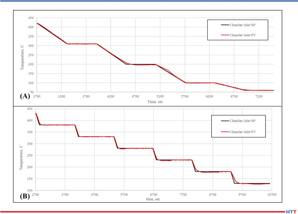
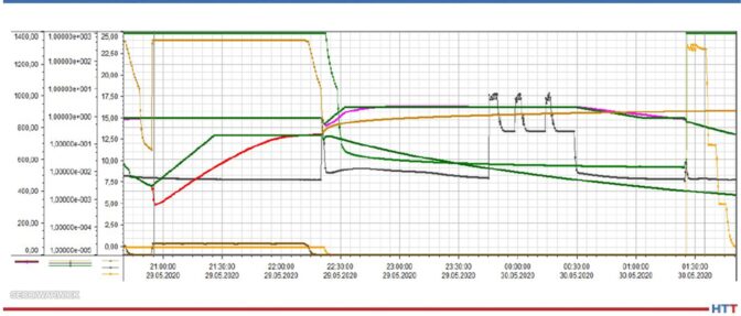
The process was carried out in the CMe-T6810-25 furnace and had the following course from the perspective of a single load (Fig. 7):
- Loading into a pre-heating chamber, heating and temperature equalization in 1382oF (750oC) (100 min in total).
- Reloading to the main heating chamber, heating and temperature equalization in 1724oF (940oC), LPC, lowering and equalizing the temperature before quenching in 1580oF (860oC), reloading to the cooling chamber (total 180 min).
- Gradual quenching at a pressure of 24, then 12 and 5 bar, discharge of the load from a quenching chamber (total of 25 min).
Source: SECO/WARWICK
Source: SECO/WARWICK
The load stayed the longest in the main heating chamber – for 180 minutes. This means that with the continuous operation of the furnace in this process, the cycle will be just 180 minutes, i.e., once every three hours the raw load will be loaded, and the processed load will be removed from the furnace.
In the next step, the parts underwent tempering at a temperature of 160oC.
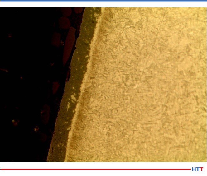
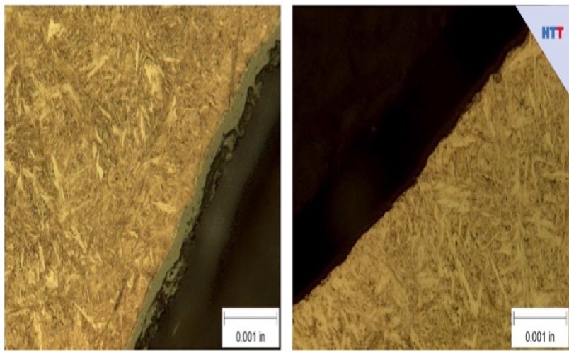
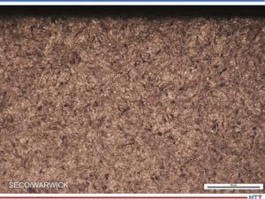
The result of the process was tested on ten parts taken from the reference corners and from the inside of the load. The correct layer structure (Fig. 8) and hardness profile (Fig. 9) were achieved, and all the requirements of the technical specification were met (Tab. 1).
Source: SECO/WARWICK
Source: SECO/WARWICK
Source: SECO/WARWICK
During the process, the consumption of the costliest energy factors was monitored and calculated, and the results per one load are as follows:
- Electricity – 550 kWh
- Liquid nitrogen – 160 kg
- Acetylene – 1.5 kg
- CO2 emissions – 0 kg
Cooling water and compressed air consumption have not been included as they have a negligible impact on process costs.
Summary: Efficiency and Economy
As a result of the process, all technological requirements have been met, obtaining the following indicators of efficiency and consumption of energy factors calculated for the entire load and per unit net weight of the load (700 kg):
- Capacity: 3h/load; 233 kg/h; 5 thousand tons/year (6500 h)
- Electricity: 550 kWh; 0.79 kWh/kg
- Liquid nitrogen: 160 kg; 0,23 kg/kg
- Acetylene: 1,5 kg; 2,1 g/kg
- CO2 emissions : 0 kg; 0 kg/kg
On this basis, it is possible to estimate the total cost of energy factors in the amount of approximately EUR 100 per load or approximately EUR 0.14/kg of net load (assuming European unit costs of 2021). It is important that these costs are not burdened by CO2 emission penalties, as can happen with more traditional furnaces.
To sum up the economic aspect, based on an example process, a CMe furnace capacity of 1,500 net tons of parts per year was achieved for 6500 hours of annual furnace operation, at a cost of energy factors of about 100 EUR per load, or 0.14 EUR per kg of parts. The economic calculation is very attractive, and the return on investment (ROI) is estimated at just a few years.
Conclusion
While the advantages of this type of vacuum application are clear from this case study, the example discussed here does not represent the full capabilities of the CMe-T6810-25 furnace, even this process can be optimized and shortened, thereby increasing the furnace's efficiency, and reducing costs. It is possible to carry out carburizing processes (LPC) or hardening alone in a 1.5 h cycle, which would double the capacity of the furnace and similarly reduce the cost of energy factors and shorten the ROI time.
For more information:
Go to www.secowarwick.com
 Find heat treating products and services when you search on Heat Treat Buyers Guide.com
Case Study: Heat Treat Equipment Meets the Future Industry Today Read More »
 A hot isostatic press (HIP) was recently delivered to T.A.G. Medical Products Corporation Ltd. (TAGMPC), a manufacturer of medical and dental solutions that improve surgical procedures. The HIP will ensure the production of implants and surgical tools with the optimal material properties required by the exacting environments in which they are used.