greg steiger

Quench Oil Management: AMS2759 & CQI-9

Given safety and performance concerns in the aerospace sector, it may be beneficial to consider quench testing that uses CQI-9 as well as AMS2759 since the automotive standard focuses on safety. Read on to understand the different approaches between these two standards in this Technical Tuesday installment, written by Michelle Bennett, quality assurance senior specialist, and Greg Steiger, senior account manager, both at Idemitsu Lubricants America.

This informative piece was first released in Heat Treat Today’s March 2025 Aerospace Heat Treating print edition.


In today’s world, there are many different quality systems available to heat treaters. Many of these, such as ISO, are quality management systems. These quality management systems are an important piece of running a successful business. However, to successfully run a heat treat business and compete in either the North American automotive market or the aerospace market, a heat treater must conform to either CQI-9 or AMS2759, or, in cases where a company processes both automotive and aerospace parts, both. This article will explain the requirements for both CQI-9 and AMS2759. It will also explain the differences between the two quality standards and any additional testing that could benefit a heat treater or how they operate their quench tank.

AIAG’s CQI-9

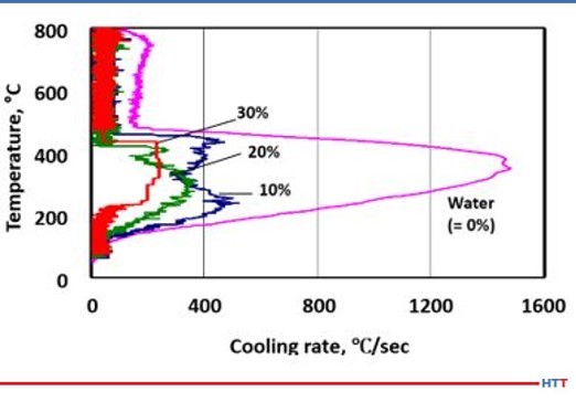
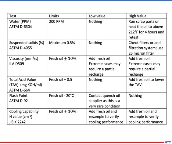
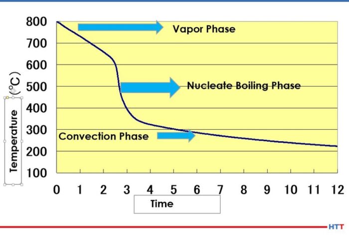
The Automotive Industry Action Group (AIAG) is a non-profit group of over 800 automotive OEMS, parts manufacturers, and service providers who oversee the requirements for CQI-9. The 4th edition is the most current edition of CQI-9. As an internal audit process, CQI-9 covers most of the heat treating process. Section 3.14 specifies the quench oil and water-soluble polymer requirements. An oil quenchant requires that the in-use oils be tested every six months and the testing must include water content, percent suspended solids, total acid number, viscosity, flash point, and cooling curve. The specification range and warning limits are based on the vendor’s requirements and recommendations. For water-based polymers, there are two tests required: concentration and quenchability. The standard does not specify a test for quenchability, however, it does make a few suggestions such as a cooling curve, viscosity, and titration.

For water-based polymers, there are two tests required: concentration and quenchability. The standard does not specify a test for quenchability, however, it does make a few suggestions such as a cooling curve, viscosity, and titration.

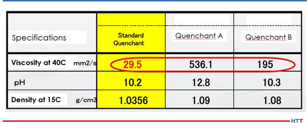
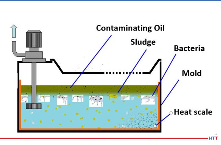
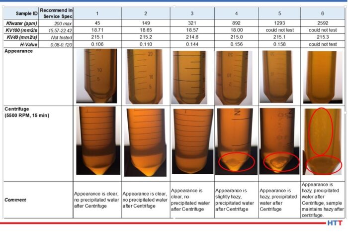
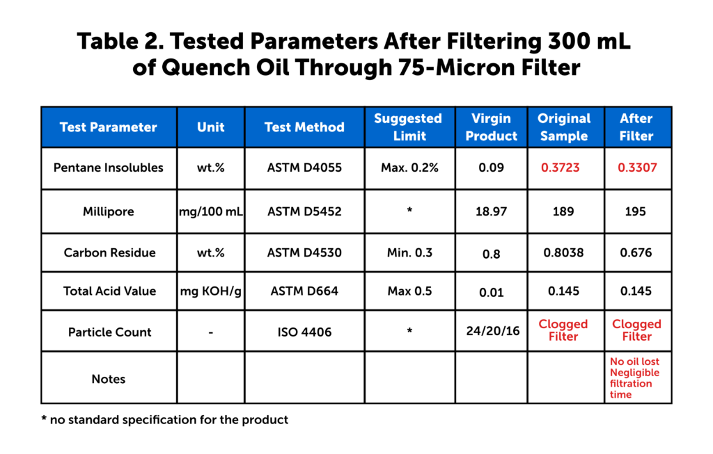
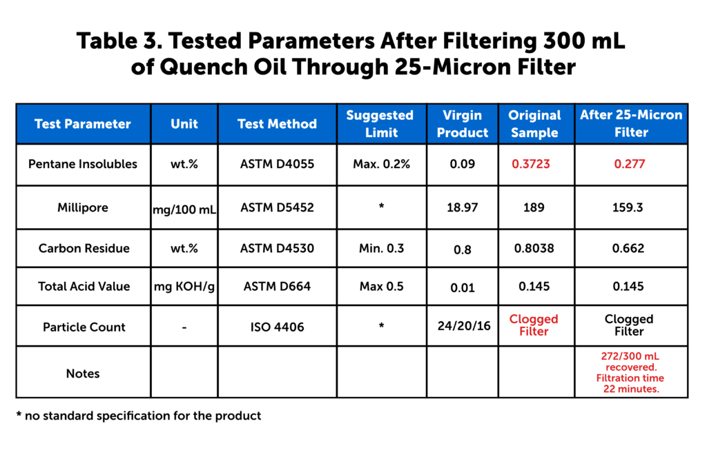
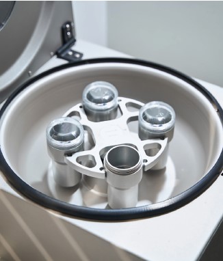
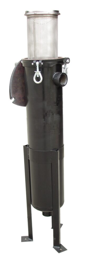
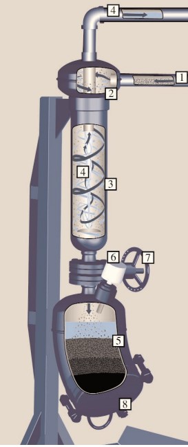
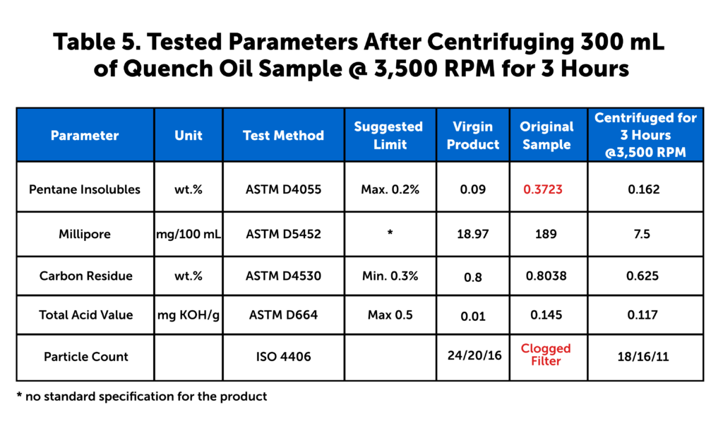
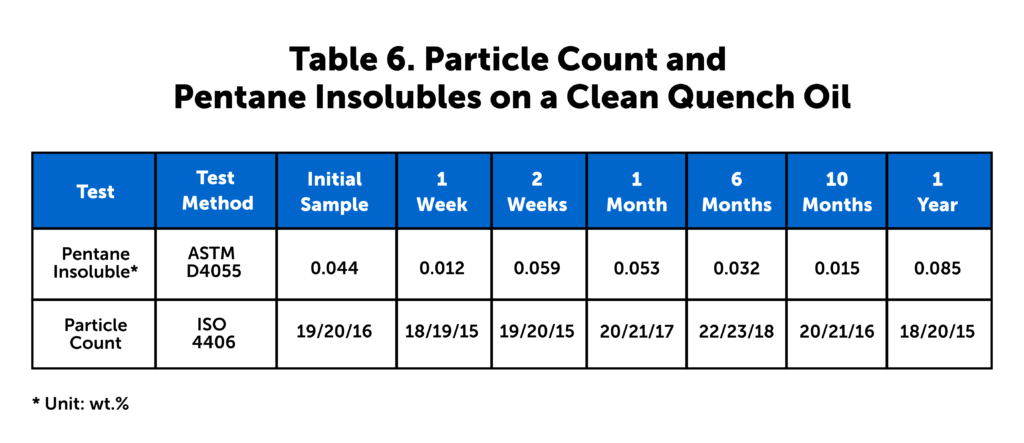
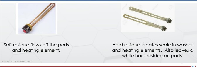
All the required testing of the quenchant is designed to achieve consistent metallurgy for safety reasons. Viscosity is monitored to look for oxidation or heat decomposition of the oil. Degradation can be in the form of oxidation, thermal breakdown, or the presence of various contaminants. Increased oil viscosity typically results in decreased heat transfer rates. A decrease in viscosity may indicate contamination. Some suspended solids are to be expected during the quenching process, but the majority of them should be filtered or centrifuged from the process. If the quantity of these contaminants becomes too high, then it can both affect the brightness of the parts, and the parts can get soft spots as the contaminants may not cool the parts at the same rate.

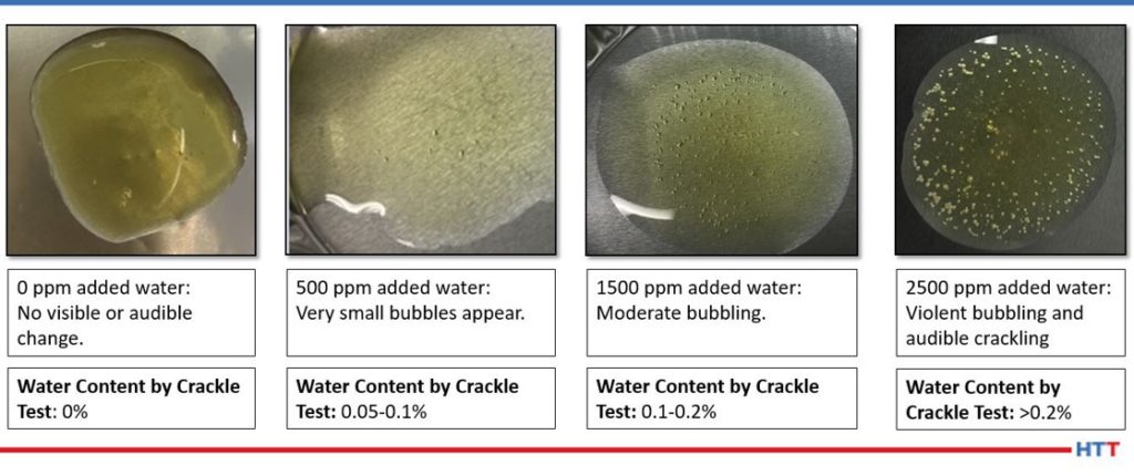
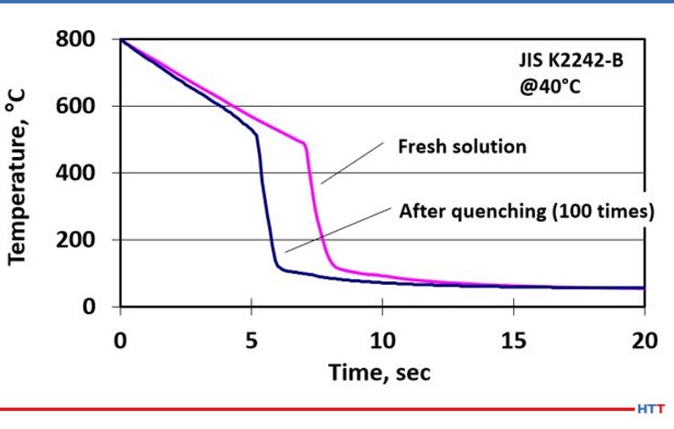
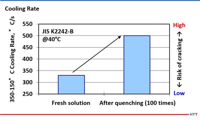
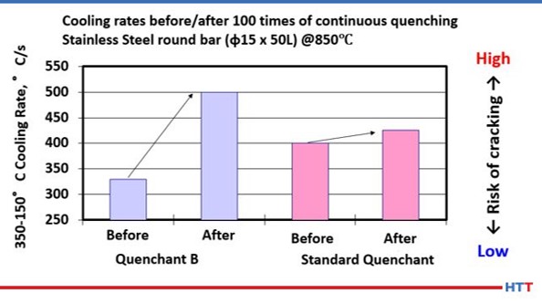
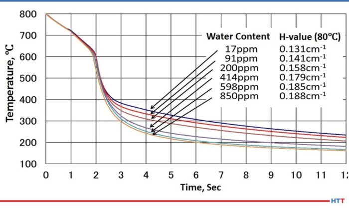
Water and flash point are both monitored for safety. If the flash point drops below the accepted range or the water content is above the acceptable range, these can cause fires during the operation. Water can also show issues with the equipment or the procedure such as leaking of anything that is water cooled, such as the outer door on a furnace. Acid value is monitored to degradation of the oil. As the oil breaks down and oxidizes, the acid value will increase. This can cause the maximum cooling rate to increase and can cause cracking or distortion on the parts. Carbon residue can be measured for two reasons. If the result is below the specification, it can show that the quench speed improver is being broken down or dragged out of the system. If the result is higher than the specification, it can show the formation of sludge, which will impact the brightness of the parts.

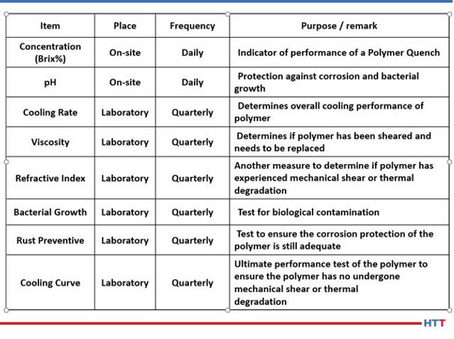
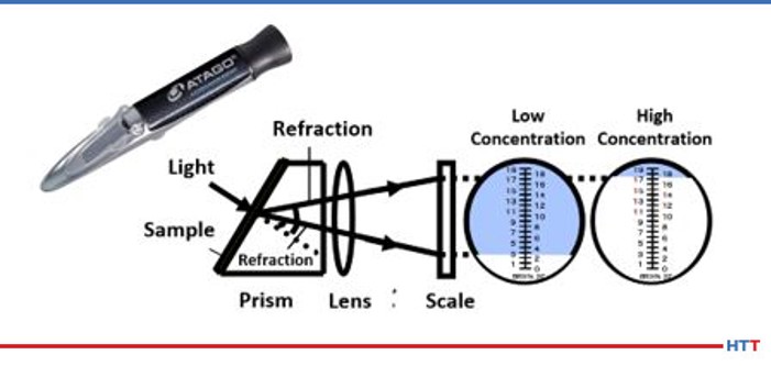
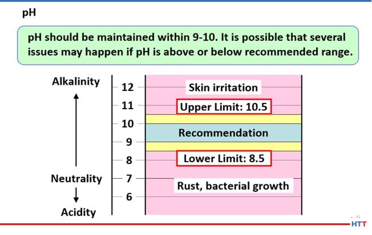
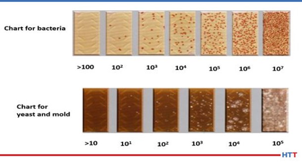
For water-based quenchants, the most common test items include pH, refractive index or brix, viscosity, and concentration calculation. Sometimes additional test items can be added, such as biological testing, to help determine and correct current issues.

Table 1. CQI-9 vs. AMS2759 quenchant requirements

SAE’s AMS2759

Just as AIAG is a non-profit business group responsible for CQI-9, SAE International is a non-profit organization responsible for AMS2759. The most recent revision of AMS2759 is Revision G. AMEC (the Aerospace Materials Engineering Committee) is responsible for maintaining this standard. Unlike CQI-9, AMS2759 requires a certificate of conformance for all shipments. Section 3.10.3 begins the requirements for quenchant testing and quenchant deliveries. Viscosity, flash point, and temperature at the maximum cooling rate must be reported on the certificate of compliance when dealing with mineral oil quenchants. For a polymer, the requirements are that the pH of the neat polymer and the neat viscosity of the polymer must both be reported on the certificate. Also required on the polymer certificate are the viscosity, pH, and the temperature at the maximum cooling rate for polymers at 20% dilution by weight.

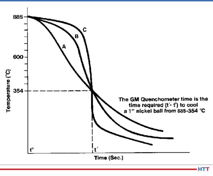
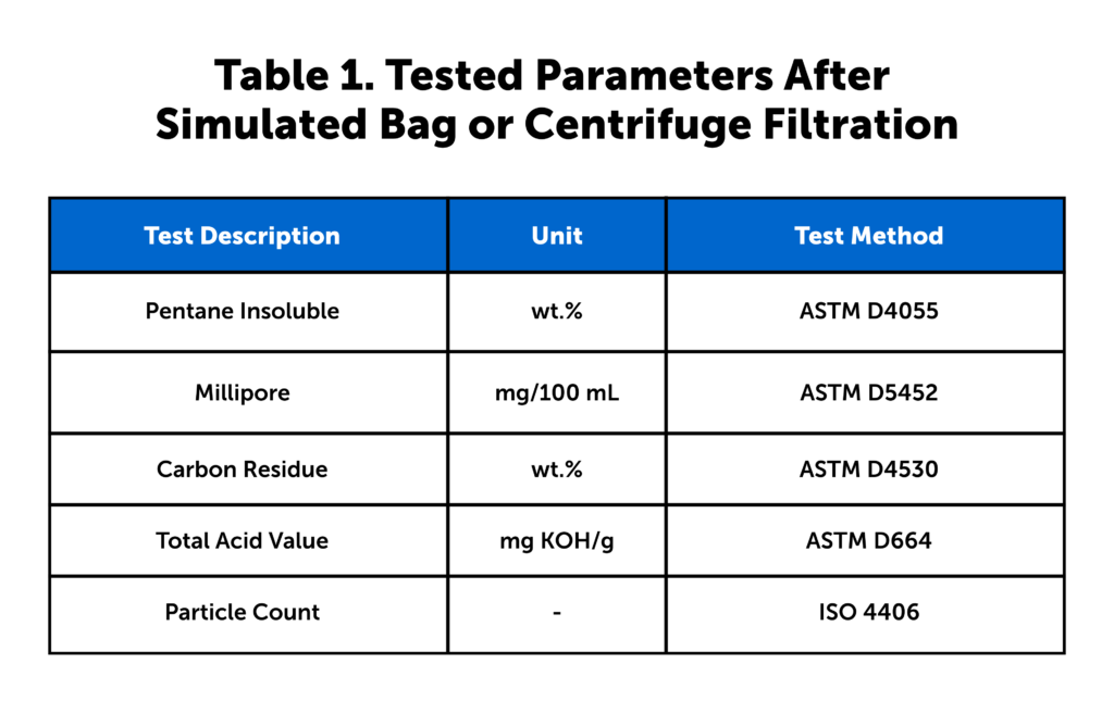
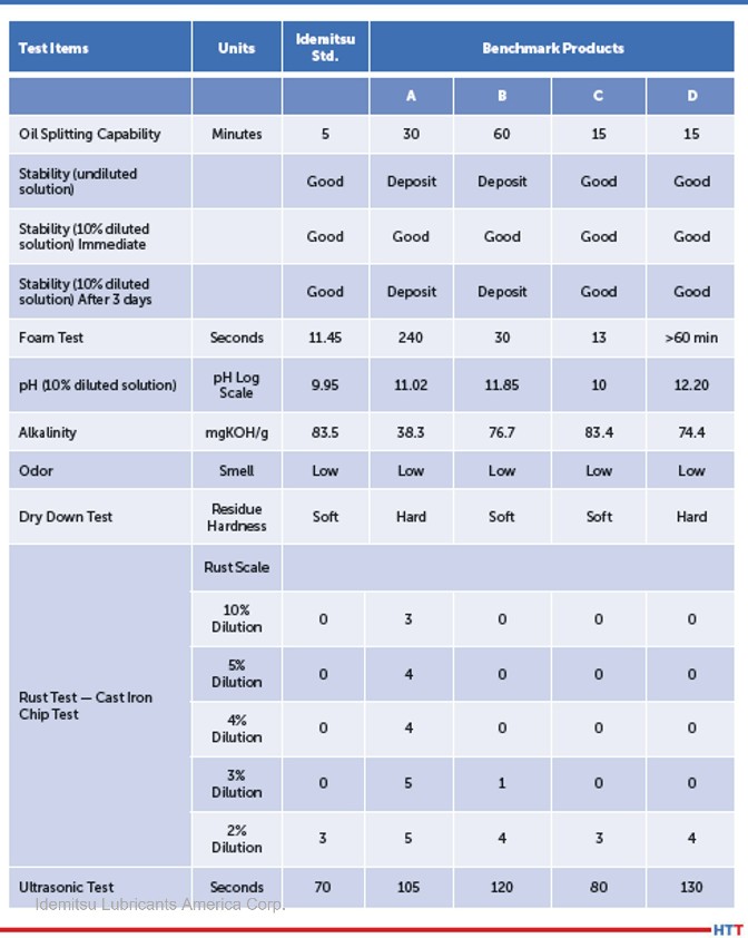
Similarly to CQI-9, AMS requires that the in-use quenchants be tested biannually. This standard, however, only requires the cooling rate and temperature at max cooling rate be tested, as well as any additional tests the supplier recommends. The AMS2759 specification does not have set limitations on the cooling rate and temperature. Instead, the specification sets the allowed upper and lower deviations from the supplier’s standard for the maximum cooling rate and the temperature at the maximum cooling rate for both oils and water-soluble polymers. The supplier should have calculated the average max cooling rate and average temperature at max cooling rate using many different blend lots and multiple test runs. This average will not vary or change based on current production values or the values for the batch that the client is currently using (Table 1).

Although both standards require having the quenchant tested bi-yearly, most quenchant suppliers encourage their clients to submit their furnace samples for testing quarterly. This ensures that the medium is being monitored frequently, and if a sample is missed or late when sampling quarterly, then the client is still within compliance for the six month testing requirements.

However, because many of the test parameters in CQI-9 are run for safety reasons along with performance reasons, it is highly advised that aerospace heat treaters should run the full suite of CQI-9 testing along with the AMS2759 testing.

Taking a Quench Sample

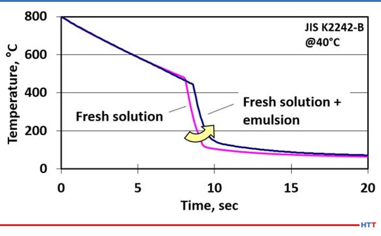
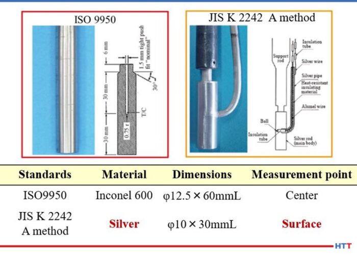
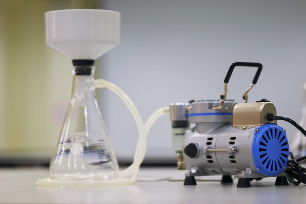
There are many different quench methods and both standards allow for any of the following variations: ASTM D6200, ISO 9950, JIS K2242, ASTM D6482, or ASTM D6549. The type of testing that is going to be conducted will determine the size of sample that will be needed. For just this quench testing, the volume of sample needed ranges from 250 milliliters to 2 liters.

As always, when taking samples, it is important to be sure to get a good representative sample of the current quenchant being used in the process. The agitation needs to be running and collected in a clean and dry container. The sampling site should be the most convenient location to safely obtain a sample. It should also be the same location for every sample. The lid also needs to be put on before the oil cools too much because the container will draw in moisture and condensation as the oil cools if it is open to the atmosphere.

Conclusion

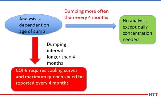
When examining the standards, there is one basic commonality: the need to run a complete cooling curve every six months. There is also a large difference in that AMS2759 does not require the full suite of testing that CQI-9 does. However, because many of the test parameters in CQI-9 are run for safety reasons along with performance reasons, it is highly advised that aerospace heat treaters should run the full suite of CQI-9 testing along with the AMS2759 testing. For automotive heat treaters, the maximum cooling rate and the temperature at maximum cooling rate is something that can be reported in the normal D6200 cooling curve test.

For manufacturers heat treating parts for aerospace, automotive, or both markets, we recommend quarterly quench samples at a minimum. The primary reason for more frequent testing is safety. Also, with the current labor shortage, heat treaters are busier than ever. If quench samples are routinely taken on a quarterly basis and are somehow missed and forgotten, there is still time to take another sample and remain in CQI-9 and AMS2759 compliance.

Remaining in compliance of these two important standards requires a lot of hard work from both the heat treater and the quenchant provider. Unless the quenchant supplier is working together in a true partnership, it will be very difficult to remain in compliance with the requirements for CQI-9 and AMS2759. But with routine monitoring, heat treaters can help to ensure quenchant and equipment have a longer life and achieve ever-tightening requirements from clients.

About The Authors:

Michelle Bennett
Quality Assurance Senior Specialist
Idemitsu Lubricants America

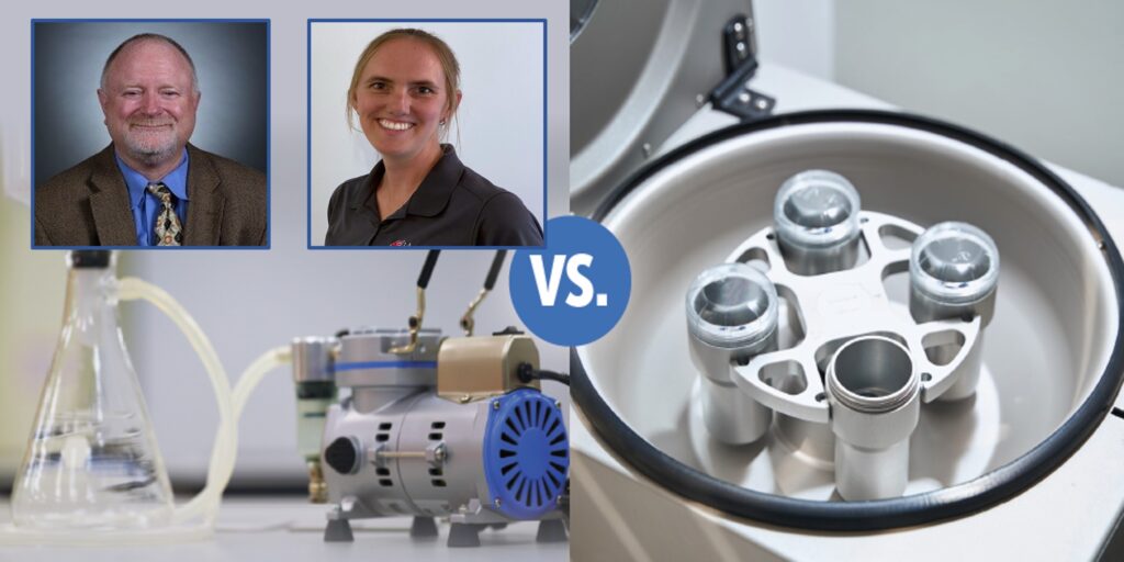
Michelle Bennett is the quality assurance senior specialist at Idemitsu Lubricants America, supervising the company’s I-LAS used oil analysis program. Over the past 12 years, she has worked in the quality control lab and the research and development department. Her bachelor’s degree is in Chemistry from Indiana University. Michelle is a recipient of Heat Treat Today’s 40 Under 40 Class of 2023 award.

Greg Steiger
Senior Account Manager
Idemitsu Lubricants America

Greg Steiger is the senior account manager at Idemitsu Lubricants America. Previous to this position, Steiger served in a variety of technical service, research and development, and sales and marketing roles for Chemtool Incorporated, Witco Chemical Company, Inc., D.A. Stuart Company, and Safety-Kleen, Inc. He obtained a BS in Chemistry from the University of Illinois at Chicago and recently earned a master’s degree in Materials Engineering at Auburn University. He is also a member of ASM International.

For more information: Contact Michelle Bennett at mbennett.8224@idemitsu.com or Greg Steiger at gsteiger.9910@idemitsu.com.


Quench Oil Management: AMS2759 & CQI-9 Read More »

Obliterate Quench Contaminates

OC

Sludge, scale, and dirt are all undesirables in quench oils that can cause detrimental effects during quenching. Bag filtration and centrifuge filtration are put to the test in this investigation. Compare the results before you make your next purchase.

This Technical Tuesday article, written by Greg Steiger, senior account manager, and Michelle Bennett, quality assurance specialist, at Idemitsu Lubricants America, was originally published in November 2023’s Vacuum Heat Treat magazine.


Introduction

The primary role of a quench oil is to dissipate the heat from a quenched load safely, quickly, and uniformly. Both sludge and heat scale have a higher heat transfer coefficient than quench oil and dissipate heat more than this quench medium. This can affect the performance of a quench oil.

To obtain the desired metallurgical results, the operation of a quench system must be both consistent and uniform. The presence of sludge from quench oil oxidation and scale within the quench oil, pump, and heat exchangers can lead to variability in key parameters such as grain size, hardness, case depth and surface finish. The best way to minimize the detrimental effects of sludge and scale is to remove these contaminants by filtration. This article will compare the two most popular types of commercial filtration available for oil quench systems: bag filters vs. centrifuge filtrations.

This article will compare the two most popular types of commercial filtration available for oil quench systems: bag filters vs. centrifuge filtrations.

Test Methods

To simulate a two-stage bag filter, the following lab procedure was followed.

A 300-mL sample of used quench oil was passed through a 75-micron filter paper. The filtrate from the 75-micron filter was then filtered through a 25-micron filter paper. To simulate the pressure typically found in an industrial bag filter, the filtration in both the 75-micron and 25-micron papers was aided by a vacuum pump that pulled used quench oil through the filter paper.

To simulate the effects of centrifugal separation, a benchtop centrifuge was used. A 300-mL sample of used quench oil was placed in a centrifuge tube and centrifuged for 25 minutes at a speed of 3,500 RPM. An additional 300-mL sample was placed in an identical centrifuge tube and centrifuged for 180 minutes at 3,500 RPM as well.

In addition to the lab testing of dirty quench oil samples, we monitored the particle count and pentane insolubles in samples from an in-use heat treating furnace. This study began with charging the furnace with clean quench oil that was filtered using a single stage 25-micron filter and collected after each filtration. At the conclusion of each timed centrifuge session, the filtrate and the centrifuged sample were tested across five tests, see Table 1.

Table 1. Tested parameters after simulated bag or centrifuge filtration (Source:
Idemitsu Lubricants America)
Note on Table 1: Pentane insolubles measure sludge and scale present in the quench oil after the filtration through the barrier filter or after the centrifuge. Millipore testing is a measure of the overall cleanliness of the quench oil after either filtration or centrifuging. Carbon residue testing measures the Conradson carbon in the filtered or centrifuged quench oil and is designed to determine if any of the quench speed improver additive in the quench oil has been removed via filtration or centrifuging. By measuring the total acid number (TAN) of the quench oil, it is possible to determine if the quench oil is becoming oxidized and beginning to create unwanted sludge. The ISO Particle Count tests for solids contamination, providing a quantitative value for the number of particles that are larger than 4 μm, 6 μm, and 14 μm.

Filtration Results

Because industrial quench oil filters are under a slight pressure, it would be very difficult to replicate this in a laboratory setting. To simulate the slight pressure found in industrial oil filters, we used a Buchner funnel connected to a vacuum pump to simulate the industrial pressure vessel. A similar setup is depicted in Figure 1.

Figure 1. Buchner funnel and laboratory vacuum pump (Source: Idemitsu Lubricants America)

The results post-filtration are depicted in Table 2 and Table 3.

Table 2. Tested parameters after filtering 300 mL of quench oil through 75-micron filter
(Source: Idemitsu Lubricants America)
Table 3. Tested parameters after filtering 300 mL of quench oil through 25-micron filter
(Source: Idemitsu Lubricants America)

Another popular method of filtration in a heat treating facility is through a centrifuge. While it is impractical to use a full-size industrial centrifuge in a lab, the same results can be achieved through the use of a smaller sample size and a benchtop centrifuge. A benchtop centrifuge similar to the one seen in Figure 2 was used to produce the results in Tables 4 and 5 (below).

Figure 2. Benchtop centrifuge (Source: Idemitsu Lubricants America)

Understanding the Test Methods: Bag/Barrier Filtration

Figure 3. Polyethylene felt filter bag and filter canister (Source: SBS Corporation)

Bag (or barrier) filtration is the most common type of filtration used in quench oil filtration. For the heat treater, there are many different size filters available, as well as different configurations varying in the number of canisters and filters. The filter creates a barrier that particles greater than the pore size in the barrier cannot pass. The primary reasons for its popularity are economics, simple operation, and design. A typical polyethylene bag filter and filter cannister can be seen in Figure 3.

The most common filter sizes are 50-micron and 25-microns. Both 5-micron and 25-micron filters were used in this investigation because the test sample contained a high level of pentane insoluble. Additionally, since it is commonly thought that using a 50-micron filter will cause blinding and clogging, we chose a 75-micorn filter and a subsequent filtration step of using a 25-micron filter to simulate a common two-stage quench oil filter.

Understanding the Test Methods: Centrifuge Filtration

Using a centrifuge to filter out sludge and scale is also commonly used in many heat treating operations. The difference between centrifugal filtration and barrier filtration is centrifugal filtration relies on gravity, friction, and centrifugal force to separate the particles from a quench oil instead of a physical barrier (Figure 4).

Figure 4. Horizontal centrifugal filtration (Source: SBS Corporation)

In the horizontal centrifugal filtration diagram, the dirty oil enters the tangential opening (section #1) and is forced into a spinning motion. A centrifugal force (occurring in section #2) is based on the spinning pentane insolubles, scale, and any other solids contained in the dirty oil.

In section #3, the friction created by the flow of the solids, scale, and other undesirables encountering the steel body of the centrifugal separator creates a low viscosity shear layer. In section 4, the clean liquid travels through a vortex and leaves through a side discharge. The slowing velocity of the undesirables allows gravity to pull them into the debris collection area in section #5. The now cleaned oil regains its velocity and continues through the vortex created by the centrifugal forces acting on the solids to a center discharge and back to the quench tank. As the debris fills section 6, a light will illuminate, indicating the receptacle is full and needs to be emptied.

Once the undesirables fill the debris collection area, an indicator light signals the receptacle is full and a gate knife control valve (section #7), is manually closed so the debris collector can be opened via the closure (section #8).

Discussion

Table 4. Tested parameters after centrifuging 300 mL of quench oil sample @ 3,500 RPM for 25 minutes (Source: Idemitsu Lubricants America)
Table 5. Tested parameters after centrifuging 300 mL of quench oil sample @ 3,500 RPM for 3 hours (Source: Idemitsu Lubricants America)

As seen in Tables 2 and 3, filtration does improve the overall cleanliness of the dirty quench oil. The weight percent of the pentane insolubles showed a significant improvement when filtered through the 25-micron fi lter. However, the level of pentane insolubles was still outside of the suggested limits for the quench oil.

This was not seen when the quench oil was filtered through a 75-micron filter. The 75-micron filter had little or no effect on the Millipore results. The Millipore results increased when filtered through a 75-micron filter. This leads us to believe some of the particles within the dirty oil were forced through the 75-micron filter and not through the 25-micron filter, as the 25-micron filter showed an improvement in Millipore results.

An ISO particle count was not possible on the original used samples or the filtered samples because the filter clogged on all three test samples.

The largest difference in results lies in the carbon residue testing. The level of carbon residue is essentially the same after both the 75-micron and 25-micron filter samples. Both of the carbon residue levels are within the normal suggested limits. However, the high level of sludge in the original dirty sample is likely removing some of the quench speed improver from the quench oil. The removal of the quench speed improver changes the performance of the quench oil over time.

In examining the results of the centrifuge testing in Tables 4 and 5, it is clear centrifuging for 25 minutes has better effect on the cleanliness of the oil sample than filtering through a 25-micron filter. The level of pentane insolubles after centrifuging for 25 minutes at 3,500 RPM is still outside of the suggested limit. However, running the centrifuge for three hours under the same conditions not only brings the pentane insolubles within the suggested limits, the Millipore and particle counts also see an improvement over the virgin oil sample results. The carbon residue
levels behave much the same as they do in the filtration tests.

What is significant is the year-long study we conducted using actual customer data. In this study, a furnace was dumped, cleaned, and then filled with clean virgin oil. The authors then tested the ISO particle counts and pentane insolubles for one year after the furnace was charged with clean oil. These results are seen in Table 6. These data show essentially no change in the particle counts and a slight improvement in the level of pentane insolubles over the one-year period.

Table 6. Particle count and pentane insolubles on a clean quench oil (Source: Idemitsu Lubricants America)

Conclusion

From the testing conducted, it is clear the filtration through a 75-micron filter has little to no effect upon the tested parameters and the performance of the quench oil. The high levels of pentane insolubles will likely clog heat exchangers, pumps, and valves within the quench system. The dirty oil will also likely cause metallurgical issues such as isolated soft spots due to the slower heat transfer of the dirty oil. The results of filtering a dirty oil through a 25-micron filter show some improvement in the pentane insoluble levels. However, the result is still outside of the recommended limits for the oil. Additionally, the ISO particle counts were not able to be tested due to the overall dirty condition of the filtered sample.

In contrast to the bag filter samples, the centrifuge samples showed a marked improvement over the dirty sample. While the pentane insoluble level was slightly out of the recommended limit for the 25-minute centrifuge sample, all results were within the recommended specifications for the three-hour centrifuge sample. In some cases, such as the particle count, the centrifuge sample had better results than the virgin sample.

While the centrifuge and filter results both show how hard it is to effectively clean a dirty quench oil, the results from the year-long study show very little difference in particle counts and a slight decrease in pentane insolubles, which can be explained through the normal addition of virgin make up oil to the quench system.

It is clear both centrifuge separation and bag filtration can improve the overall condition of a dirty quench oil. However, if your level of dirt, sludge, and scale reaches near the levels of the tested sample, a centrifuge is better at removing these than filtration. Overall, the data show the most important and efficient method is to begin filtering a clean quench oil as soon as the quench tank is charged.

About The Authors

Greg Steiger is the senior account manager at Idemitsu Lubricants America. Previous to this position, Steiger served in a variety of technical service, research and development, and sales and marketing roles for Chemtool Incorporated, Witco Chemical Company, Inc., D.A. Stuart Company, and Safety-Kleen, Inc. He obtained a BS in Chemistry from the University of Illinois at Chicago and recently earned a master’s degree in Materials Engineering at Auburn University. He is also a member of ASM International.

Michelle Bennett is the quality assurance specialist at Idemitsu Lubricants America, supervising the company’s I-LAS used oil analysis program. Over the past 12 years, she has worked in the quality control lab and the research and development department. Her bachelor’s degree is in Chemistry from Indiana University. Michelle is a recipient of Heat Treat Today’s 40 Under 40 Class of 2023 award.

For more information:
Contact Greg at gsteiger.9910@idemitsu.com
Contact Michelle at mbennett.8224@idemitsu.com.


Find heat treating products and services when you search on Heat Treat Buyers Guide.com

Obliterate Quench Contaminates Read More »

Not To Be Neglected: Heat Treat Furnace Maintenance Tips

OCFundamentals of furnace maintenance sometimes fall between that tricky area of realizing their importance and getting pushed to the end of the to-do list. This original content piece shares tips to bring the fundamentals back to where they belong: at the top of the to-do list. 


3 Tips From "Effective Integral Quench Furnace Maintenance" Article

Ben Gasbarre
President, Industrial Furnace Systems
Gasbarre Thermal Processing Systems

  1.  Safety First | Whether the furnace is in operation, or it is having down time, proper safety measures must be in place. Personal protective equipment, proper shut down of power sources, and even the buddy system are topics taken in to consideration.
  2. Asset Management System | Have up-to-date maintenance records available to any and all employees. "Ensuring important information, such as alloy replacements, burner tuning, or control calibration information, can help operations and maintenance personnel as they plan and assess future equipment needs," comments Ben Gasbarre, president industrial furnace systems at Gasbarre Thermal Processing Systems.
  3.  Cleaning | Reminders include: change filters on combustion blowers, clean things like burners and flame curtains, clean out endothermic gas lines, burn off manual probes at least once a week, etc.

.

3 Tips From "Furnace Diagnostics for Validation, Preventative Maintenance, and R&M" Article

Daniel Hill, PE
Sales Engineer
AFC-Holcroft
Source: AFC-Holcroft

  1.  Rules and Regulations | The military and energy industries are sectors that have strict standards to follow. Different heat treating shops are using a software module to maintain furnace data, looking at data reports to make sure the furnace systems are running properly.
  2. Timely Maintenance | Making a maintenance plan and then following it means that no tasks are overlooked or forgotten.
  3. After Repairs and Adjustment | Make sure that after trouble shooting and performing repairs, the software generated reports are examined and that furnaces continue to be maintained. Daniel Hill, PE, sales engineer at AFC-Holcroft says, "This saves valuable time and resources, improves availability, and likely increases profitability."

.

3 Tips From "How CQI-9 Compliant Quench Oil Analysis Can Aid in Proper Care of Quench Oil" Article

Greg Steiger
Senior Key Account Manager
Idemitsu Lubricants America

  1. Proper Levels of Sludge and Water Quench | Failing to keep the quench oil clean results in problems on surface finish. Maintain the quench from the start by filtering, cleaning, and replenishing to keep end product surfaces more acceptable.
  2. Frequency of Sampling | "[The] more often a quench oil is analyzed, the easier it is to use the quench oil analysis as a tool in the proper care of a quench oil," explains Greg Steiger, senior key account manager at Idemitsu Lubricants America.
  3. Regular Addition of Fresh Oil | Proper maintenance of quench oil will result in some loss through filtration. Be sure to replenish.

Find heat treating products and services when you search on Heat Treat Buyers Guide.com


Not To Be Neglected: Heat Treat Furnace Maintenance Tips Read More »

Heat Treat Quench Questions Answered with Radio Review

OCTwice a month, Heat Treat Today publishes an episode of Heat Treat Radio, an industry-specific podcast that covers topics in the aerospace, automotive, medical, energy, and general manufacturing realms. Each episode provides industry knowledge straight from the experts.

Stay abreast of quenching tips, techniques, and training --- especially in the auto industry --- with this original content piece that draws from three video/audio episodes.


Heat Treat Radio: The Greenness and Goodness of Salt Quenching with Bill Disler

Bill Disler
President, CEO
AFC-Holcroft
Source: AFC-Holcroft

Sure, salt quenching has been around for quite some time, but this method is coming more to the forefront when we consider some of the concerns and costs of oil quenching. In this Heat Treat Radio episode, listen in to Bill Disler of AFC-Holcroft discuss the pros and cons of salt quenching. His brief overview and then salt versus other quench options will leave you ready to embrace quenching at your heat treat shop.

Contact us with your Reader Feedback!

"I’d say, in general, the most common thoughts with salt are to use it for bainitic quenching. If you’re quenching into a bainitic structure, salt has always been the only way to do this," comments Bill. "But what we’re seeing the growth into, and much more activity, is martensitic quench." As you listen, key into the point of salt quenching offering a "green-minded" solution due to recyclability.

Get the complete episode here.

Heat Treat Radio: Water in Your Quench with Greg Steiger, Idemitsu

Greg Steiger
Senior Key Account Manager
Idemitsu Lubricants America

Water in the quench tank? How much is too much? What do you do to get rid of it? Is it possible to prevent water from getting into the tank? Greg Steiger of Idemitsu answers these questions and more in this essential episode.

"Our research has shown that basically about 200-250 ppm water, you start to get uneven cooling," Greg Steiger cautions. "When you start getting up to large amounts of water, somewhere around 750 ppm to over 1000 ppm, it becomes a safety issue."

The entire episode gives answers to how to identify, prevent, and remove water in the quench.

Heat Treat Radio: All Things Auto Industry Quenching with Scott MacKenzie

D. Scott MacKenzie, Ph.D
Senior Research -- Metallurgy
Quaker Houghton, Inc.

This interview gets to some nitty gritty details regarding quenching and the shift to electric vehicles. What does the future of heat treating look like for electric vehicles (EVs)? Where is aluminum heat treat fitting in? Listen in to get industry insight on these answers. Scott MacKenzie of Quaker Houghton also explores simulation and modeling, the need for trained metallurgists in our industry, and more broad heat treat considerations.

"The next thing you have to understand is the quenchant itself," Scott MacKenzie advises. "You have to understand the physical properties."

Take in the full episode here.


.

Search for heat treat solution providers and suppliers on Heat Treat Buyers Guide.com


Heat Treat Quench Questions Answered with Radio Review Read More »

Using a Data-Driven Approach To Operate Cleaners in a Heat Treatment Facility

OCWhen was the last time the parts washer was cleaned? For many heat treaters, answering this question and keeping data on cleaning schedules and outcomes may not be at the top of their priority list. Learn how a data-driven approach to cleaning heat treated parts can have an impact well beyond the cleaning phase. 

This Technical Tuesday article, written by Greg Steiger, senior account manager at Idemitsu Lubricants America Corp., was first published in Heat Treat Today's August 2022 Automotive print edition.


Greg Steiger
Senior Key Account Manager
Idemitsu Lubricants America

Introduction

For many years heat treaters have virtually ignored their washers. It was not uncommon for these washers to be dumped and recharged whenever someone thought about it. Often the question “When was the last dump and recharge?” was met with the “I don’t know” shoulder shrug or “When the parts were dirty.” So why do parts need to be cleaner than ever before? The easy answer is because it is what customers are demanding. The more difficult answer is because as quality standards have improved over the last several decades, the need for parts with tighter tolerances has also increased.

Contact us with your Reader Feedback!

Many readers will wonder what part cleanliness has to do with tighter tolerances. The answer is the quench oil residue that was once acceptable to leave on the parts affects the tolerances of the part. For example, a buildup of oil in the threads of a part will have an impact on how the part threads into its mating part. Cleanliness affects post heat treat processes such as plating and painting as many residues cannot be plated or painted over. Part cleanliness also influences the shop environment in a heat treat operation. A clean, oil free part will not produce smoke in temper like a part with oil residues will.

Furthermore, when asked how the washer was recharged the typical answer was to drain the cleaner solution and then replace the cleaner solution with fresh water and enough cleaner to bring the concertation to the desired level and then restarting the washer. There was virtually no thought to removing the sludge that had built up over the years since the washer was last thoroughly cleaned. Little time was spent mucking out the sludge, and even less time and thought were expended on determining if the spray nozzles were clogged or properly aimed at the load. When energy, labor, cleaner chemistry, and disposal costs were all very low, this was the typical method of operating washers.

Now (with labor, disposal, energy, and cleaner prices all increasing along with the nationwide labor shortage) is the time to change those old habits and recognize the preclean and post quench washers are two ways to improve part cleanliness and the bottom line. The method of change for these habits is to allow data to be the guide in operating the washers in a heat treatment operation. The data will determine what the optimal concentration range is to obtain the cleanest parts. The data will show when the soil loading in the washer is too high. The data will reveal the maximum tank life for the cleaner solution. In other words, data should be used to maximize the efficiency of the washers.

Basic Cleaner Chemistries

The term alkalinity in its most basic description is a pH above 7.0. At this pH, the cleaner efficacy is improved as is the overall rust protection of the parts in the quenched load and any mild steel used in the washer construction. All alkaline cleaners share several types of common raw materials. They are alkaline builders, surfactants, corrosion inhibitors, and sequestering agents. However, where the
cleaner chemistries differ is in the types of alkaline builders used to create the alkaline pH. Many older formulations and less expensive products use caustics, carbonates, phosphates, and silicates as their alkaline builders.

Figure 1. Hard residue of powdered alkaline builders
Source: Idemitsu Lubricants America

While these are now commonly used in the liquid form, they are all powder based. The biggest issue with using powder based alkaline builders lies in the residue they leave behind when the water evaporates. These residues are the hard white residues seen in Figure 1.

Additionally, when the water evaporates from cleaners using these alkaline builders the residue can clog the spray nozzles within the washer cabinet. More recent formulations have begun using a product called an amine as an alkaline builder. Amines are liquids mixed with water. Therefore, when the water evaporates a liquid is still left behind. The film from an amine is more uniform, does not leave a powdery residue, and does not clog the spray nozzles in the washer cabinet. Additionally, amines have better buffering capabilities and help keep the pH of the cleaner in the mild pH range of between 9.0 and 10.5. When water is sprayed on a warm piece of steel, the water beads up and forms droplets.

The purpose of the surfactants in an alkaline cleaner is to prevent this from happening. The surfactants help the cleaner to wet out over the load more evenly. Surfactants also assist in the cleaning process by providing detergency to the cleaner. To provide short-term indoor corrosion protection, alkaline cleaners also have a short-term corrosion inhibitor formulated into the cleaner. This short-term protection is only intended to provide work-in-process protection. This protection is typically no more than a few days of protected indoor storage. Lastly, sequestering agents are used to allow the alkaline cleaners to be used in hard water. The sequestering agents chemically react with the minerals in hard water preventing them from precipitating out as hard water soaps and salts.

Alkaline cleaners can also be distinguished by those that emulsify the oils they remove and those that separate the oil they remove. In a typical dunk spray post quench washer, the load enters the washer and is lowered into the cleaner solution where the solution is agitated. The agitation allows the surfactants or detergents to provide the cleaning. During this period of agitation, the cleaner and quench oil combine to form a mechanical emulsion and potentially, a chemical emulsion. (The difference between a mechanical and chemical emulsion is a chemical emulsion is a more permanent emulsion and a mechanical emulsion stops when the mechanical agitation stops.) Once the mechanical agitation stops, a still period, or dwell, should then occur. This will allow the mechanically emulsified oil to separate from the cleaner solution. After this dwell period is over, an air knife or a set of nozzles will blow the oil layer into a separate chamber where the oil can be skimmed and removed from the cleaner solution. The elevator then brings the load up and out of the cleaner solution and into the spray cabinet. At this point it becomes highly imperative as much oil as possible is removed from the top of the cleaner solution. If the oil is not removed, the elevator will simply bring the load through a layer of oil, which is redeposited throughout the load. Once the load is in the spray cabinet, the cleaner solution is pumped through the spray nozzles onto the load. This spraying action is to remove any lingering soils and remaining oils. The solution pick-ups for these nozzles are typically in the middle portion of the dunk tank.

Designers of the equipment chose this spot because any free-floating oil will not be picked up and sprayed through the nozzles. For cleaners emulsifying oils the cleaner and oil emulsion is then sprayed and redeposited back onto the load. This will create issues in the temper where the water evaporates, and the oil left behind will create smoke and other vapors.

Figure 2. A 5% cleaner solution heated to 160°F was
made of each cleaner to test oil separation abilities.
Source: Idemitsu Lubricants America Corp.

For cleaners not emulsifying oils, the oil is not redeposited on the parts and the smoke and other vapors from emulsifying cleaners are greatly reduced or eliminated in temper. Figure 2 shows the difference between emulsifying and non-emulsifying cleaners.

While the source of alkalinity does not create smoke and other vapor issues in temper, the alkalinity source does create issues in temper and in the spray portion of the washer. In the temper, cleaners using alkaline builders such as caustics, carbonates, phosphates, and silicates will leave behind a white powder residue as seen in Figure 1. This residue is caused when the water in the cleaner solution evaporates and leaves behind the powder of the alkaline builders. Water evaporation in cleaners with powder alkaline builders will cause spray nozzles to clog and heating elements to foul. Cleaners using an amine as the alkaline builders do not have these issues. The difference in heating elements can be seen in Figure 3.

Selecting a Cleaner

Figure 3. Heating element comparison of an amine cleaner vs. powdered alkaline builder cleaner
Source: Idemitsu Lubricants America

The proper selection of a cleaner can be the difference between a highly satisfied customer and a completely dissatisfied customer. The requirements for a cleaner are as follows:
• Part cleanliness that exceeds customer
expectations
• Long sump life
• No residue
• Ability to split quench oil from cleaner
• Rust-free parts
• Low foam
• Low to moderate pH
• Hard water stability

When selecting a cleaner, a heat treater typically has two opportunities to influence the overall part
cleanliness. The first opportunity lies before the heat treatment process begins with a precleaning step. The second opportunity is with the post quench cleaning operations. When choosing a cleaner for these operations it is important to know what soil will be removed during the cleaning. The answer to the post quench cleaning is obvious, a quench oil. However, the soils on the parts incoming to the heat treatment process vary greatly. These soils may include oil and water based rust preventatives, water soluble coolants, cutting oils, and mill oils.

Typically, the soils removed before the parts are placed into the furnace are easier to remove than the quench oil from the post quench washer. This allows for the same cleaner to be used in both operations. By using the same cleaner in both preclean washer and post quench washer, heat treaters don’t have to worry about purchasing two different cleaners or have the concern of mixing the cleaners by placing the incorrect cleaner in the wrong washer system.

Once the soils to be removed have been identified, the next criteria to look at in selecting a cleaner are the operating temperatures of the washer, the pH of the cleaner, and foaming characteristics of the cleaner. Typically, the foaming characteristics and the operating temperature of the washer are directly related.

The type of surfactants or detergent additive used in alkaline cleaners have a property called the cloud point. At operating temperatures below the cloud point, the cleaner will form a dense and heavy foam that inhibits the cleaning efficacy of the cleaner. At operating temperatures above the cloud point, the surfactants are soluble in water and work as detergents and do not create foaming. An operating temperature of 140°F–160°F is the ideal operating temperature to remain above the cloud point, maximize the efficacy of the detergents, and minimize foaming tendencies of the cleaner. The cloud point phenomena can be seen in Figure 4.

Figure 4. Demonstration of a surfactant cloud point
Source: Idemitsu Lubricants America

The higher the pH the easier it is to clean many soils from the parts. The pH of a cleaner plays multiple roles in the parts cleaning process. A pH above 8.0 also helps provide corrosion protection on mild and carbon steels. However, as the pH climbs, skin sensitivity becomes an issue. At a high caustic pH such as 12 or above chemical burns on skin can occur. At lower pH levels of between 9 and 10.5, such as those provided by amine-based chemistry, skin sensitivity is greatly reduced.

Another advantage to amine-based chemistry lies in the lack of a perceptible residue that is often seen on parts after temper or around the washer itself. Figure 5 shows a typical part residue after temper from an emulsifying caustic cleaner. Figure 6 shows the residue found on a washer using a caustic cleaner.

In addition to leaving the residues seen in Figures 5 and 6, caustic cleaners also have the potential disadvantage of clogging spray nozzles when the water evaporates leaving behind the same type of residue in the spray nozzle. The clogged spray nozzles will then reduce the efficacy of not only the cleaner, but also the oil skimmer as well as the spray nozzles that are used to push the floating oil into the quenchant tank where floating oil is removed via an oil skimmer.

A cleaner should be compatible with hard water. In many areas the aquifers and wells where water is drawn from contain high amounts of minerals and salts. These hard water minerals and salts exacerbate any residue issues and create an ideal environment for rust and corrosion to begin. If the minerals and salts are left unchecked, they will eventually form chloride ions and mini voltaic cells. These mini voltaic cells are the beginning stages of the corrosion process. The sequestering agents in an alkaline cleaner will chemically react with the minerals and salts thereby not allowing the free chloride ions and the mini voltaic cells to form.

Using Data To Efficiently Operate a Washer

There are many reasons heat treaters dump and recharge their parts washers. The most common reasons typically are: “we dump the washer once a month because we always have”; “we dump the washer whenever the parts get dirty”; or “we never dump the washer.” Very infrequently is the answer “the soil loading is too high.” That is because to know what the soil loading is, the washer has to be operated by using data. Using data, heat treaters can optimize the efficacy of the cleaner solution, maximize the dump interval of the cleaner, reduce the amount of sludge in the washer, and lessen downtime.

The key in establishing a dump cycle is to know when the cleaner has reached its soil loading limit. Typically, this is around 2%. Soil loading is the amount of soil that is mixed in with the cleaner. The soil consists of a mixture of the soils removed, dissolved salts, and soaps along with anything else that makes its way into the washer. The 2% limit will be reached quicker in the post quench washer than in the preclean washer as more soil is removed in the post quench washer. In addition to soil loading, the proper data approach should also include the cleaner concentration by an alkalinity titration, concertation by Brix, tramp oil, cast iron chip rust test, and chloride level.

A brief explanation of each test and the reasons for performing the test are individually listed below.

pH

A good pH range is between 9.2 and 10.5. Within this range, most people coming into contact with the cleaner solution will not have an issue with skin sensitivity. At a pH above 10.5 skin sensitivity dramatically increases. As the pH begins to trend lower and eventually becomes acid below 7, the corrosion protection properties of the cleaner decline.

Concentration by Brix

This test measures everything that is dissolved within the cleaner solution. This includes salts, soaps, and removed soils. The Brix% is measured with a handheld refractometer reading in Brix%. The Brix% is then compared to a chart specific to the cleaner being tested. The Brix% will typically be higher than the concertation when tested via an alkalinity titration as the Brix% captures the amount of cleaner dissolved in water, along with salts, soaps, and removed soils. The concertation limits for the Brix% should have a maximum no more than 2.0% above the concentration by alkalinity.

Concentration by Alkalinity

This is a titration that can be performed in a lab or at the washer. A weak acid such as 0.1N HCl and an indicator such as phenolphthalein is used. The method and concentration multiplier depends on the specific cleaner used. Many methods count drops of acid used, while others use milliliters used to change the color of the indicator. The supplier of the cleaner will likely provide an initial concentration test kit and instructions on how to use the kit. A good concentration range for a preclean washer is between 2% and 3% and a post quench washer should have a concertation range of between 4% and 5%.

Soil Loading

The difference between the concentration by Brix% and concentration by alkalinity is the soil loading. This value should not exceed 2%. When the soil loading exceeds 2% it is time for a dump and recharge of the cleaner solution.

Tramp Oil

A tramp oil test measures the ability of the skimmer to effectively remove the quench oil from the top of the cleaner. This test is simple to run and can be run by most heat treaters. Simply fill a 100 ml graduated cylinder with the cleaner solution from either the preclean or post quench washer and allow the cylinder to stand idle for 20 minutes. Then simply read the amount of oil that has separated from the cleaner. A maximum level of 2% tramp oil shows the oil skimmer is effectively removing the tramp oi from the cleaner.

Cast Iron Chip Rust Test

Running the cast iron chip test requires dry machined cast iron chips and is best left to your cleaner supplier. The purpose of running the cast iron chip test is to ensure the corrosion protection formulated into the cleaner is not being depleted. This test uses a scale published by ASTM with a rating system of 0 to 5, where 5 is the worst and 0 is the best. To successfully pass this test a result of no more than 1 should be achieved. It is important to remember, cast iron chips have more surface area than a steel part and cast iron is also more porous and prone to oxidation than steel. Therefore, a test result of 1 is not a reason for concern.

Chloride

The chloride test is another test that is best left up to your cleaner supplier because the easiest way to test is through expensive instrumentation. The purpose of testing for chlorides is to prevent the situation for a mini voltaic cell to form. If the chloride level exceeds 150 ppm in a cleaner solution a mini voltaic cell can form and the corrosion process begins. As this process begins, the pH will begin to fall as will the corrosion protection of the cleaner.

In Table 1 several commercially available cleaners were tested and evaluated using the criteria above. The cleaners tested were both those that emulsified oils and split the oils. Testing also includes both amine-based and caustic-based cleaners.

Discussion

Imagine if the dump cycle went from four weeks for a post quench washer to 10 weeks for the same washer by using a data-driven approach described in this paper. The savings would not only be in the cost of the cleaner used but would extend to less downtime and more efficient use of maintenance as employees no longer need to clean out a washer every month. Customer expectations for clean parts have changed over the past years. What was acceptable as little as five years ago is no longer acceptable today. What hasn’t changed is the way preclean and post quench washers have operated. While it is difficult to assign an economic value to exceeding the cleanliness standards of customers, it is not difficult to assign an economic value to parts not meeting your customer’s standards. That economic cost can be as high as lost business. By using a data-driven approach the decisions made in how to operate a washer are no longer kneejerk reactions. Instead, these decisions have a historical data-driven approach to them.

About the Author: Greg Steiger is the senior key account manager of  Idemitsu Lubricants America Corp. Previously, Steiger served in a variety of research and development, technical service, and sales marketing roles for Chemtool, Inc., Witco Chemical Corporation, D.A. Stuart, and Safety-Kleen. He obtained a BS in chemistry from the University of Illinois at Chicago and recently earned a master’s degree in materials engineering at Auburn University. He is also a member of ASM. Contact Greg at gsteiger.9910@idemitsu.com.


Find heat treating products and services when you search on Heat Treat Buyers Guide.com


Using a Data-Driven Approach To Operate Cleaners in a Heat Treatment Facility Read More »

Heat Treat Radio #74: Water in Your Quench with Greg Steiger, Idemitsu

Heat Treat Radio host, Doug Glenn, talks with Greg Steiger of Idemitsu Lubricants America Corp. about the causes and dangers of water in your quench tank, how to know if you have too much, and what to do about it if you do. This highly-informative episode is a must watch/listen for those who oil quench.

Below, you can watch the video, listen to the podcast by clicking on the audio play button, or read an edited transcript.


The following transcript has been edited for your reading enjoyment.

Doug Glenn (DG):  Greg, welcome to Heat Treat Radio. This is the first time you’ve been on, and I know we’ve talked about doing this for quite a while, so, welcome!

Greg Steiger (GS):  Thank you, it’s my pleasure.

DG: I asked the question, before we hit the record button, but I think we need to ask the question again:  The big white flag in the background with the W, you need to tell us about that.

GS:  That’s the flag that they fly outside of Wrigley Field every time the Cubs win. They’ve been doing this for almost a century so that way when they were only playing day baseball and you could come home on the L, you could see if the Cubs won or lost without looking at a box score.

DG:  That’s great! Now, you are not in the Chicago area, are you?

GS:  No, I’m in the Columbia, SC area, but I was born and raised in the Chicago area.

DG:  So, you’re a Cubby fan.

GS:  I am.

DG:  Being from Pittsburgh, I forgive you for that.

So, Greg, first thing, can you give our listeners and viewers a brief background about yourself and then we’ll jump into the water topic, so to speak?

GS:  Sure. I got into this industry when I graduated from college in 1984 as a formulating chemist. I eventually worked my way into, what we call, customer service or tech service, where I’d go out and visit customers, run product trials if customers had problems. I worked my way into laboratory management and eventually sales and marketing. I’ve been at Idemitsu for the past 9 years. Since I’ve been at Idemitsu, I’ve earned a master’s degree in materials engineering, and I’ve learned a lot about heat treat and it’s really become my passion. I am currently the market segment leader for heat treat products for Idemitsu.

DG:  I should congratulate you on that degree, by the way. I know a year or so ago, you were still working on that, so that’s great!

GS:  May 6th I graduate.

DG:  Tell us, just briefly, for those who might not know about Idemitsu. We can see it on your shirt but tell us about them a little bit, so people have a sense.

GS:  Idemitsu is a very well-kept secret here in the U.S. They are actually the 8th largest oil company in the world. We are a Japanese owned company. There is about an 85-90% chance that no matter what vehicle you drive, you’ve got some of our fluids in it. The largest market share is the automotive air conditioning compressor market, but basically, if you drive a Honda, Mazda, Subaru, or Toyota, it left the plant with our engine oils, our transmission fluids in it at the factory.

When it comes to quench oils on the industrial side, Idemitsu is actually the 2nd largest quench oil provider in the world. Even though we’re Japanese, all of our heat products, in general, are made and blended here in the U.S.; we don’t import anything from Japan for our heat treat products.

DG:  Very interesting. So, a big company — somebody worth paying attention to, I think is the point. You’re right — it’s the best kept secret. We’re trying to work to not make it so secret.

GS:  We’re doing what we can, Doug.

DG:  This next question I’m going to ask you is very, very basic and most people listening I’m sure will know this but there may be some who don’t: Why is water in quench oil a problem?

GS:  A little bit of water is not a problem because it will happen naturally through condensation, but when you start to get too much water in there, a couple of things happen. Our research has shown that basically about 200-250 ppm water, you start to get uneven cooling.

A quench oil is not a completely homogenous fluid; it’s possible to have water in one area of the tank and no water in the other so you can get different cooling speeds in different areas of the tank. When you start getting up to large amounts of water, somewhere around 750 ppm to over 1000 ppm, it becomes a safety issue. What happens is — when water turns into steam, it actually expands. Most things when they get warmer, they contract, but water is the opposite — it expands. It expands 1600 times at boiling and the hotter the steam gets, the more it expands.

"A little bit of water is not a problem because it will happen naturally through condensation, but when you start to get too much water in there, a couple of things happen. Our research has shown that basically about 200-250 ppm water, you start to get uneven cooling."

Think of it: If you have a gallon of water in a 3,000-gallon quench tank, when you boil that water, it turns into 1600 gallons of steam, and it’s got nowhere to go but up and out of the quench oil and it’s going to carry the quench oil with it onto flame curtains, other hotspots on the furnace, and that’s why it becomes so dangerous.

DG:  It’s really the risk of explosion, in a sense. That’s basically what we’re talking about. I could be wrong, but my gut feeling is that a vast majority of quench fires are started because of water that happened or simply the product not getting down into the quench fast enough. But a lot of it is caused by carrying water in with the part.

GS:  Not necessarily on the part but being in the oil itself through various means. As I said, it happens naturally every time you heat an oil up and you cool it down, you get condensation, but that’s usually only a few parts per million, and every time you drop a load in, you’re driving that water off.

DG:  Right. Raising up the temperature and therefore boiling off the water.

GS:  Right.

DG:  This is a follow-up question into what we were just talking about, and maybe we’ve answered it:  Where does the water come from? Is it typically just condensation or what are the top ways water gets into the tank?

GS:  Condensation is something we can’t prevent because we live in a hot, humid environment. But what we can prevent is human error, and that’s where most of the water comes from. For instance, if a heat treater has their quench oil stored outside, perhaps in totes — it’s particularly important to make sure that the caps and lids on these totes or drums are very tight and secure because otherwise they’ll get condensation in there and rainwater in there.

We’ve seen instances where people are working on a furnace, and they will hit the sprinkles and the sprinklers will set off and put water into the quench oil. Heat treat furnace doors and, not so much anymore but, heat exchanges where water cooled. Anything that is under pressure is eventually going to leak and that’s why you see companies going to air-cooled heat exchangers. It’s still more difficult to get that air-cooled door and there is still some water in those doors. Like I say, anything under pressure is eventually going to leak and that’s where you see some of the water infiltration, as well.

DG:  Typically speaking, how warm or how cool is the oil in a quench tank? You mentioned about condensation being caused by when it cools down, you’re going to have some condensation in there. Where do we run those tanks?

GS:  It depends on if you’re using a hot oil or a cold oil. A cold oil is basically an oil that you add some heat to get it around 130-160 F, then you use your heat exchangers to keep taking the heat away when you quench the load in there. A hot oil you add heat to constantly because you want to keep that typically 250-300 F. In a hot oil, you really don’t have a lot of issues with water, unless the furnace goes down and then you get a lot more condensation than anything else. Now, cold oil, you have issues with water because you’re not above the evaporation point of the water.

DG:  The bottom line is: If you’ve got too much water in the quench tank, it’s an issue.

Tell us about the measurement. How do we know if we’ve got water in there, and how do we know how much we have?

GS:  Well, there are some portable test kits out there. The ones I’m familiar with are made by the Hach Company. You can purchase these from industrial supply houses like McMaster-Carr or places like that. They will give you ppm’s of water.

You heard a lot of old-timers always talk about crackle tests. That is not an effective way to determine how much water is in there. Our studies have shown that you can get as much as 1000-1500 ppm of water before that oil starts to crackle. The way you run a crackle test is — you take a hot panel, (that’s hotter than the boiling point of water), put a couple of drops of oil on it and if it crackles, there is water in there. Sometimes, the oil is so thick, it doesn’t really crackle, and you can’t see it until you get too much water in there.

The way all quench oil providers do it in their lab is something called a Karl Fischer titration. This is not something that the typical heat treater would have in their lab — it’s a relatively expensive piece of equipment. We use automated ones because we do so many at a time, but you can buy manual ones, if you’d like, and those are a little bit less expensive, but again, you’re talking about laboratory equipment and you’re talking about thousands of dollars instead of hundreds of dollars.

Another way to determine if you have water in your quench oil, especially on lighter colored quench oils, is to take a flashlight, put it in a clear beaker, and take a flashlight and put that flashlight at the bottom of the beaker. If nothing in that beaker is hazy and everything is very clear and amber and you can see through it, chances are there is no water in it. But if it’s a dark quench oil, like a lot of cold oils are where it’s almost jet black, the flashlight won’t do you any good.

One of our customers has talked about using a paste. Unfortunately, I don’t know the manufacturer of it, but what he did is he took a paste and put it on a wooden stick and stirred it all throughout its tank. The paste didn’t turn colors, so he knew there was no water in it. To prove that the paste was still good, he actually licked a finger and put it onto the paste and the past turned pink.

DG:  This paste that you put on the stick, it doesn’t dissolve into the liquid — it’s just testing whether there is water there. And if it changes color, then you’ve got water. We’ll have to find out what that is and maybe we can put a note about that on the screen.

DG:  Probably the best, most reasonable method that doesn’t cost so much, is maybe getting one of those testing kits. Do you have suggestions, Greg, on how frequently a heat treater ought to be checking his or her tank for water?

GS:  I would say weekly. I don’t think it needs to be tested any more unless you think there’s a problem. If there’s a problem, obviously, test as often as you need to. But weekly is good enough.

Again, when you’re dropping a load into quench oil, you’re anywhere from 1300-1800 F, so when you drop that load in, you’re driving almost all of the water off that would be in the quench oil from condensation. It’s just if you’re worried about some sort of a human error, that’s when you want to take more frequent testing.

DG:  So, it’s going to be somewhat dependent on your process.

How about the material that you are quenching? Are some materials more sensitive to water than others, or is not really an issue?

GS:  Not really. It’s more of an issue of part geometry. And that goes really for distortion and cracking along with the water. A little bit of water can crack a very thin part, but on a very thick part, it may not have much effect at all.

DG:  How about cosmetics? I know that some people are very concerned with cosmetics. Is water in the quench oil going to cause any issue with cosmetics, such as spotting?

GS:  Short-term no, long-term yes. What causes a lot of stains is oxidation. Water, when it heats up, will actually dissociate into hydrogen and oxygen. The hydrogen won’t oxidize the oil, but the oxygen does. That’s one of the reasons why heat treaters use flame curtains — not to allow the oxygen from the atmosphere into the furnace. At the temperatures that you heat treat at, it doesn’t take much oxygen presence to oxidize not only the parts, but also the oil.

DG:  We talked briefly about why water is a problem. We talked about measuring it and trying to determine if you have an issue. Let’s move on to this: Ok, we’ve got water in the quench and it’s at an unacceptable level. What do we do?

GS:  There are a few ways to do it. It really depends on what level of water you’re at, how safe you feel, and how soon do you need that furnace. Many furnaces have a bottom drain. If you turn the agitation off in the quench oil, the water is going to be heavier and denser than the oil and it will sink to the bottom. This is going to take a couple of days, at least. If you’re looking at 1000 ppm or so, this is probably the best way to do it, because then you can drain from the bottom of the tank until you no longer see water coming off and you see oil.

Let’s say you’ve got 500 ppm or 400. We recommend an upper limit of 200. For that you can run some scrap through your furnace. Again, you have to be incredibly careful because you’re not really at what would be an explosive level, but you don’t want to run good parts through there because you may get some strange hardness results — they may be higher in hardness than what you’re expecting.

Another way, (again, this will take some time), is to actually bring the temperature of your oil above the boiling point of water. If you brought it up to about 220 degrees or so, as the oil starts to evaporate, you will see bubbles and a froth (almost like a head you would see on a beer) come to the top of the oil tank. Once that’s gone, chances are your water is gone.

The last thing you can do is do a complete dump, drain, and recharge. But I would caution anybody who suspects that they have water in their quench oil, and you want to do any of this testing — before you run any loads through that furnace (with good parts), make sure you send a sample overnight to your quench oil provider and they can test it for you. That’s the biggest issue.

DG:  I want to back up because you said something that I didn’t catch the fullness of, I don’t think. You said one of the solutions was to simply run scrap parts through your furnace?

GS:  Yes.

DG:  Now, how does that help you eliminate the water?

GS:  Again, you’re taking these scrap parts and they come through your furnace and the furnace may be 1800-2200 degrees. When you dump that load into the quench, if you’ve got just a small amount of excess water, it will evaporate off.

DG:  Gotcha. You’re basically bringing up the temperature of the oil so that the water evaporates.

GS:  Exactly. You’re almost flashing it off.

DG:  We talked about the draining and the replacing. I know of some companies recycle their oil. Any thoughts or comments about that that heat treaters ought to be aware?

GS:  Yes, because that’s also a potential source of contamination for water because they skim the oil off of their cleaner tanks. I’ve been at a lot of heat treaters where they have these reclamation systems — they heat the oil up, theoretically they drive all the water off, but not always. Again, this is part of that human error. As a quench oil company, we understand that our customers are doing this, especially with oil continuing to go up. But, again, working with your quench oil supplier here is key because we’ll analyze the samples for our customers and tell them if they’re getting all that water off. Obviously, it’s in the quench oil supplier’s best interest, and the customer’s best interest, to make sure everybody is safe. If a plant burns down, nobody wins.

DG:  We’ve discussed why water is a problem, how we measure it to make sure we know it, and then what to do with it. Being a quench expert, do you have any other resources, if someone was interested in learning more, whether it be specifically about water in quench oil or just other quench resources — is there anything that you can recommend for further reading?

GS:  I wrote a series of articles on quench oil and how to get water out of the quench oil for your publication Heat Treat Today. Also, how to use your analysis from your quench oil supplier to operate your furnace. You should always let the data tell you how to operate a furnace and not do something just because we’ve always done it this way.

Others, such as Scott Mackenzie, have presented papers. I know back in 2018, there was a conference Thermal Processing in Motion by ASM, and he presented a paper there on how to get rid of water out of quench oil.

DG:  Any other resources you’d like to recommend to people?

GS:  Use your quench oil supplier. They are the experts. They’re the ones that have all of the testing equipment you need and use them as a resource. Quite frankly, if you don’t get the service from your current quench oil supplier, there are a bunch of us out there, and that’s how we distinguish ourselves — through our service — so find somebody with better service.

DG:  There are a number of quench oil suppliers out there. I know some of them are not specifically targeting the heat treat market, but people still use them because they’re a local distributor or something like that.

I want to recommend to people that if you’re having trouble with the processing of parts, whether it be the mechanical properties and things of that sort, and you have a hint that it might be quench-related, it’s probably best to get ahold of people like Greg, who are actually focused in more on the heat treat market. They may have some good recommendations. This is just an encouragement to people that if you’re not using a heat treat specific quench company, there are a couple of them out there and, obviously, Greg at Idemitsu, we appreciate you giving us a little bit of expertise today.

Thanks very much, Greg. Appreciate it very much and appreciate you being with us.

GS:  Thanks for your time, Doug. I appreciate the opportunity.

For more information:

Greg's phone: 919-935-9910.

Greg's email: gsteiger.9910@idemitsu.com

Doug Glenn <br> Publisher <br> Heat Treat Today

Doug Glenn
Publisher
Heat Treat Today


To find other Heat Treat Radio episodes, go to www.heattreattoday.com/radio and look in the list of Heat Treat Radio episodes listed.


Find heat treating products and services when you search on Heat Treat Buyers Guide.com


Heat Treat Radio #74: Water in Your Quench with Greg Steiger, Idemitsu Read More »

The Selection, Care, and Maintenance of a Polymer Quenchant

OC“Many metallurgists or heat treat engineers only think in terms of water or oil for quenching steel. Water is the most common quench medium, followed by oil. However, polymer quenchants have made significant inroads into these traditional choices…”

In today’s Technical Tuesday feature, Greg Steiger and Keisuke Kuroda of Idemitsu Lubricants America share an original content article on the composition and uses of polymer quenchants, specifically polyalkylene glycol.


Introduction

Greg Steiger
Senior Key Account Manager
Idemitsu Lubricants America

Many metallurgists or heat treat engineers only think in terms of water or oil for quenching steel. Water is the most common quench medium, followed by oil. However, polymer quenchants have made significant inroads into these traditional choices.

The advantages of water are abundance, low cost, lack of flammability, and the ability to achieve high hardness. Still, there are many disadvantages associated with water as well. These are all associated with the very aggressive quench obtained from water. Issues such as quench cracking, distortion and soft spots from uneven cooling are just a few of the drawbacks of water.

Keisuke Kuroda
Technical Advisor
Idemitsu Lubricants America

Oil quenchants do not offer the hardenability of a water quench because the quench speeds of oil are more limited than those of water. Quench oils also pose a fire hazard which can create workplace environmental issues such as smoke generated during the quench process. Additionally, the disposal costs of used quench oils continue to increase as time goes on. Limited options for applications requiring a quench speed between oil and water were available until water soluble polymers were introduced to the market in the mid-20th century.

With water soluble polymers heat treaters could vary the concentration in water to achieve oil like quench speeds. Furthermore, using warm or hot water provided the ability to increase the quench speed to approach that of water yet minimize the quench cracks and distortion due to the high quench severity of oils.

Historically, polymer quenchants were used in hardening steel and in nonferrous (aluminum) applications and continues to be a popular choice for these operations today. However, its use in induction hardening has grown exponentially, and as such, polymer quenchants have become much more important to modern manufacturing and heat treating.

1. Types of polymer quenchants

Today, there are many different types of polymers in use. Examples of these types of polymers include polyacrylates, polyvinyl alcohol, polyvinylpyrrolidone, polyethyloxazoline, polyethylene glycol and the most popular polyalkylene glycol (or PAG). The types of polymers and their characteristics are seen below in Table #1.

Table #1 Polymer types and their primary characteristics

While each of the chemistries listed in Table #1 are in use today, the scope of this paper will be limited to the most used chemistry, polyalkylene glycol.

1.1 Polyalkylene glycols and inverse solubility

A polymer quenchant is composed of more than just the water-soluble polymer. In typical polyalkylene glycol polymer quenchants, water makes up the largest ingredient. However, there are additives such as ferrous corrosion inhibitors, nonferrous stain and oxidation inhibitors, alkalinity buffers, defoaming agent, biocides along with the polyalkylene glycol in typical polyalkylene glycol quenchants. Chemically, a polyalkylene glycol consists of nothing more than carbon, hydrogen, and oxygen. The chemical structure for a polyalkylene glycol is seen in Figure #1. The m and n represent the number of molecules contained in the polymer. The higher the values of m and n, the thicker and more viscous the polymer becomes.

Figure #1 Polyalkylene Glycol Chemical Structure

In examining the chemical structure of a polyalkylene glycol it can be seen there or OH and H molecules on each end of the polymer. As we learned in high school science classes, like dissolves like. Water is composed of these same compounds and this is why the polymer is soluble in water. However, a polyalkylene glycol exhibits inverse solubility at higher temperatures due to a phenomenon called a cloud point. At 70°C (approximately 160°F) the polyalkylene polymer becomes insoluble in water. By being no longer soluble in water the polymer then coats the part being quenched and controls the cooling rate to provide a slower quench speed than pure water thereby reducing or eliminating the risk of quench cracking and distortion. A demonstration of the cloud point phenomena is shown in Figure #2.

Figure #2 Polyalkylene Glycol Cloud point

In examining cooling curves generated using the test method JIS K2242-B Heat Treating Fluids cooling curves for plain water and c solution can be examined. Using the cooling curves shown in Figure 3 the cooling curve for the water is on the left and the cooling curve for the polyalkylene glycol (PAG) is on the right. As cooling curves are shifted to the right the quench severity and quench speed both decrease. The inset shows a simulation of how a polyalkylene glycol polymer exhibits inverse solubility at elevated temperatures and coats the part being quenched to control the cooling speed.

Figure #3

One of the unique properties a polyalkylene glycol possess that a quench oil does not is the ability to vary the cooling rate of the solution by concentration. Unlike an oil, a polyalkylene glycol solution is diluted with water and the amount of polymer to control the cooling rate varies with concentration. For instance, a 10% concentration of a polyalkylene glycol solution will have a faster and more severe quench rate compared to a 30% solution of the same polyalkylene glycol. Figure #4 shows a comparison of cooling speeds of various polyalkylene glycol solutions versus pure water.

Figure #4 The cooling rate of polyalkylene glycol solutions versus pure water.

2. The deterioration of a polyalkylene glycol polymer

While modern polyalkylene glycol quenchants are formulated to provide excellent corrosion and biological protection. The simple act of using them to quench parts creates conditions where the polymer deteriorates. As stated above, it the function polymer becomes inversely soluble at elevated temperatures and coat the parts to control cooling. This will also cause the depletion of the polymer and other additives through drag out. Similarly, as hot parts come into contact with the polymer, pyrolysis occurs. As a result of pumping, the polymer solution the polymer is mechanically sheared.

The solution undergoes mechanical shearing when a solution is continually circulated through a system by using a mechanical pump. The less viscous the fluid the less susceptible the fluid is to mechanical shearing. Table 2 shows the viscosity of three widely available commercial polyalkylene glycol polymers.

Viscosity and density of typical polyalkylene glycol polymers

Table 2 shows that Quenchant A is over 18 times greater than the viscosity of the viscosity of the standard quenchant, and Quenchant B is over 6 times the viscosity of the standard quenchant. Noting change in viscosity makes it is easy to see how mechanical shearing can affect polymers in different ways. As the solution is sheared and loses viscosity, the cooling properties of the polymer also change. Simple physics shows that the heat transfer properties of a thin, less viscous fluid, such as water, dissipates heat better than a thick, viscous fluid such as maple syrup.

In addition to mechanical shearing reducing the viscosity of the polymer, pyrolysis also creates a similar breakdown in the polymer. Pyrolysis is a chemical process where the polymer becomes thinner and less viscous due to the long chain length polymer being thermally broken into less viscous shorter chain polymers at high temperatures. Figure #5 shows the effects of mechanical shearing and pyrolysis on a short chain, less viscous standard quenchant polymer.

Figure #5 A depiction of viscous polymer subjected to pyrolysis after 100 quenches.

The severity of how pyrolysis and shearing affect the quench as the cooling speed of the polymer quenchant has clearly increased. This increase in the cooling speed is shown as the curve has shifted to the left. The increase in cooling speed and quench severity are directly related to the thinning polymer viscosity, which is directly attributable to mechanical shear and pyrolysis. To further emphasize this point, let’s look at how users of polyalkylene glycol quenchants determine concentration.

A handheld refractometer is typically used to measure what is often referred to as the refractometer reading. Some users and suppliers of polymer quenches instead use the proper term Brix%. The Brix% measures the amount of polymer dissolved in water and the contaminants within the polymer tank. Contaminants can be thought of as anything dissolved or emulsified in water. Several examples of dissolvable materials include hard water minerals such as calcium, or magnesium as well as any water soluble coolants or rust preventatives used in machining prior to heat treating. Some emulsified oils can be common machine oils, like hydraulic oil, that have leaked into the polymer tank.

Because all these dissolved or emulsified materials can impact the concentration levels of the polymer, most suppliers will ask for a periodic check of the solution be done using a benchtop refractometer. This reading measures how much light passing through a prism is refracted or bent by the polymer. Because the dissolved contaminants do not refract the light this is a more accurate method of determining the polymer concentration. However, it is a lab based piece of equipment and is not portable and must be liquid cooled to 20°C (68°F). Therefore, the portable Brix meter is typically preferred in heat treating operations.

The most preventable form of deterioration of a polymer quench is from contamination by tramp oils, bacteria and in severe cases mold. Tramp oils are oils in the fluid that are not formulated into the quenchant. Because a polyalkylene glycol polymer does not contain oil any oil in the solution it is considered to be tramp oil. Regarding bacteria, there are two basic types: aerobic and anaerobic. Aerobic bacteria can live in the presence of oxygen and anaerobic bacteria thrive in oxygen depleted environments. The goal for users of polymer quench is not to eliminate bacteria entirely. This is because we do not live in a sterile environment. The water we drink, food we eat, and the air we breathe all contain bacteria. Instead, the goal of polymer quenchant suppliers and users is to prevent anaerobic bacteria and its “Monday morning odors.” Figure #6 shows a mockup of a typical sump containing a polymer quenchant and various contaminants.

Figure #6 Mockup of a Polymer Quenchant Sump

Above, the sludge layer consists of a mixture of tramp oil and polymer that has not gone back into solution. The most likely source of the tramp oil is from hydraulic oil or other machine oil leaks. This layer creates an impermeable layer against oxygen, leading to anaerobic bacterial growth. The tramp oil layer may be removed using an effective tramp oil skimmer. The anaerobic bacteria produce the rotten egg smell of hydrogen sulfide. The solution to eliminating the anaerobic bacteria is very simple. The removal of the tramp oil layer will allow oxygen to permeate through the solution through normal usage. However, removing the tramp oil layer is not enough. The second portion of the sludge layer is the polyalkylene glycol that emulsified with the tramp oil. Removing the tramp oil will cause this heavier than water polymer to sink to the bottom of the tank. This heavy polymer will prevent oxygen from reaching the material below the polymer once again creating a zone of anaerobic bacterial growth. The solution here is to use a shorter chain, less viscous polymer that will require less agitation to resolubilize in water at lower temperatures.

The effects on cooling speed are seen when a fresh solution of polymer quench is compared to the cooling speed of the same fresh polymer solution when a small amount of emulsified tramp oil and polymer is added to the same fresh polymer solution. This results in a shift of the cooling curve to the right, which slows the overall cooling speed and can result in lower case depth and softer than expected hardness results. The cooling curve is seen Figure #7.

Figure #7 These are the cooling curves of fresh polymer and fresh polymer mixed with tramp oil emulsion.

Another very common source of polymer deterioration is by contamination of heat scale which can easily be removed via filtration. Most individual induction hardening machines use an internal filter media bed. The micron size of these media filters can vary from the small ~2-3 micron to the large ~50 micron. For larger central systems and through hardening furnaces a canister filtration system is typically used. The micron size of the filtration media is typically an economic decision as the smaller pore size increases the cost of the filter. Also, the smaller the pore size the quicker the media will blind. A happy medium between cleanliness of the polymer solution and economics is typically found between 10- and 25-micron filter media.

Figure #8 CQI-9 Flow Chart

While CQI-9 requires only a daily concentration check and a cooling curve analysis for systems over four-months old, many suppliers of polymer quenchants recommend additional tests such as pH, viscosity, refractive index and other testing that is not practical for users of polymer quenchants to perform. Table #3 lists the test and frequency of the suggested test for a polymer quench solution.

Table #3 Suggested Tests and Frequencies for a Polymer Quench Solution

3. CQI-9 testing 

This section will describe the testing required under CQI-9 as well as the frequencies and the reasons behind the suggested periodic tests.

As mentioned earlier in this paper a daily concentration check is needed for a polymer solution.  The most convenient and easiest method is to use a handheld refractometer.  The operation of the handheld refractometer is seen in Figure #9.

Figure #9 Operation of a Handheld Refractometer

As previously noted, the mechanical shearing and effects of pyrolysis on a polymer are a reduction in the viscosity of the polymer in solution.  Additionally, these same effects change the cooling properties of the polymer, as seen in Figure #6; the shifting of the cooling curve only describes the overall cooling curve of the polymer solution.

However, CQI-9 requires a cooling curve analysis.  As a part of a compete cooling curve analysis, the cooling rate of the polymer should also be determined.  Because there is a direct relationship between viscosity and cooling rate, it follows that as the effects of mechanical shearing and pyrolysis reduce the viscosity of the polymer in solution the cooling speed of the polymer will also increase as shown in Figure #101

Figure #10 Effects of Pyrolysis on Polymer Viscosity

Knowing the pH of a solution is imperative for a few reasons. The higher the pH the higher the alkalinity and the better the protection against bacterial attack. Alkalinity is a measure of protection against corrosion. However, having too high of a pH can result in skin irritation. In Figure 11 below, the reader can see what pH manufacturers of polymer quenchants recommend.

Figure #11 Recommended pH Range

To run the bacterial testing on a polymer solution requires a special media called an agar to grow the bacteria colonies. These aerobic colonies are measured as a power of 10. Typically, these colonies are measured in the range of >100 to 10(7). In rare cases yeast and mold may also grow in a polymer quenchant. Once again, the colonies are measured in powers of 10. The typical range is >10 to 10(5). Figure #12 shows a pictogram of each level of bacterial and yeast and mold contamination. It is best to let the polymer supplier run this testing since it is dependent on sample handling and testing at a specified constant.

Figure #12 Agar Chart for Bacterial, Yeast, and Mold Testing

The last piece of maintenance to be addressed in this paper is the proper mixing of a polymer. Water should be added to the tank first. Once the water level reaches approximately ¾ of the full level, the water additions can end. The next step is to agitate the water while slowly adding in the polymer. It is important that the polymer not be added before the water as the polymer is much denser than the water. This will cause the water to remain on top of the polymer and will result in incomplete mixing. Once the polymer has been completely mixed into the water, a handheld refractometer can be used to determine the concentration, and then any needed water or polymer additions can be made.

Conclusion

This paper showed that the ability of a polyalkylene glycol to effectively quench and harden carbon steels is determined by a variety of factors:

  • Concentration
  • Polymer chain length
  • Viscosity of polymer
  • Mechanical shearing
  • Pyrolysis
  • Age of the polymer quenchant

The cooling speed of a polymer quenchant by concentration can be seen in Figure #4. The cooling speed varies by concentration because the amount of water present in the solution varies. The less dense water dissipates the heat faster than ticker denser polymer. Figure #13 shows the cooling curves of Quenchant A and the standard quenchant at concentrations of 10%, 20% and 30%. In Figure #13 the reader will notice less variation in the cooling curves for the standard quenchant compared to Quenchant A. This is due to the major differences in viscosity of the two products shown in Table #2.

Mechanical shearing will affect the cooling rate of a polymer by causing the viscosity of a thick polymer to thin out and become less viscous. Figure #14 shows how selecting a polymer with a polymer with a lower viscosity that is less resistant to mechanical shear and pyrolysis will exhibit less change in the cooling rate after continuous quenching.

Figure #13 Comparison of Colling Rates by Viscosity a After Continuous Quenching

Figure #14 Volume Savings Using Customer Data

In summary, a less viscous polymer is preferable due to the consistency of the quench, cooling speeds, and longer sump life than a more viscous polymer. Additionally, it will require less agitation to remix with water once the temperature of the solution is below the inverse solubility temperature of the polymer. Because the polymer remixes easily with water it does not plate out on the machines and fixtures and the carryout on the parts is greatly reduced. Since there is less plate out on the fixtures and machines along with the polymer remixing with water, there is a reduced need to dump the machine sump due to house cleaning issues. When the polymer goes back into solution, it does not settle to the bottom of the tank where it can create an environment for anaerobic bacteria growth as well. Figure #14 shows the annual volume reduction experienced when an actual customer switched to a lower viscosity polymer which resulted in a longer sump life and less drag out.


REFERENCES:
1. K. Kuroda, G. Steiger. The Importance and the Proper Way to Monitor Polymer Quenches. 2020 Furnaces North America. (All figures and tables are taken from this source.)


About the Authors: Greg Steiger is the sr. key account manager of Idemitsu Lubricants America. Previously, Steiger served in a variety of research and development, technical service, and sales marketing roles for Chemtool, Inc., Witco Chemical Corporation, D.A. Stuart, and Safety-Kleen. He obtained a BSc in chemistry from the University of Illinois at Chicago and is currently pursuing a master’s degree in materials engineering at Auburn University. He is also a member of ASM.

Keisuke Kuroda is the technical advisor for a line of industrial products which includes quench products for Idemitsu Lubricants America.  Before joining Idemitsu in 2013, Keisuke held various sales and marketing positions.  Keisuke holds a master’s degree in physics from Kobe University.

The Selection, Care, and Maintenance of a Polymer Quenchant Read More »

How CQI-9 Compliant Quench Oil Analysis Can Aid in Proper Care of Quench Oil

OCCQI-9 compliance demands adherence to the standards for the purpose of excellence in automotive heat treating. Poorly maintained quench oil can cost heat treaters in many areas. 

In this Heat Treat Today Technical Tuesday featureGreg Steiger, senior key account manager at Idemitsu Lubricants America, shares how costly quench oil issues can be addressed through proper adherence to the CQI-9 quench oil testing protocols. Let us know if you’d like to see more Original Content features by emailing editor@heattreattoday.com.


Greg Steiger
Sr. Key Account Manager
Idemitsu Lubricants America

Introduction

A poorly maintained quench oil can cost a heat treater in more ways than simply the cost of having to replace the oil.  The costs can quickly expand to include those associated with poor quality.  For example, costs associated with part rejects, or rework and downstream costs for shot blasting, or third-party inspection are often the cause of poor quench oil maintenance.  Dirty or poorly maintained oils can affect part cleanliness, surface hardness, and surface finish.  For instance, it is well known that a heavily oxidized oil may create surface stains that must be shot blasted to remove.  High molecular weight sludge or excessive water can create surface hardness issues.  Many of these issues can be addressed through proper adherence to the quench oil testing protocols established by CQI-9.

How can CQI-9 help?

CQI-9 is designed as a tool to help heat treaters produce consistent parts.  Using a CQI-9 compliant quench oil analysis can also be a very powerful tool in a heat treaters tool kit.  Just as the level of carburization is influenced by the carbon potential of a carburizing atmosphere, the cooling speed of the oil influences microstructure formation and microstructure composition along with mechanical properties such as hardness as well as tensile and yield strength. Furthermore, the cooling speed is dependent upon the viscosity of the oil, the amount of sludge, moisture level, and oxidation of the oil.  All of these are tested on a regular basis under the requirements of CQI-9, ISO TS 16949, and most quality systems adopted by modern heat treaters.  All of the tested parameters required under CQI-9 will be addressed individually later in this paper.

What is CQI-9?

The member companies of the Automotive Industry Action Group (AIAG) encompassing automotive manufacturers and their Tier I suppliers have enacted an industry heat treating standard called CQI-91.  This standard was originally a standalone standard designed and adhered to primarily by North American OEMs and Tier I suppliers as a quality tool to create consistent documented processes within the heat treating industry with the goal of producing consistent reproducible results.  Since that first implementation of CQI-9, the standard has now been incorporated into the ISO TS 16949 standard and is now adhered to by most automotive OEMs and their Tier I suppliers.  The full range of management responsibilities, material handling, and equipment operations of the CQI-9 standard is beyond the scope of this paper.   Instead we will be discussing the used quench oil analysis requirements of CQI-9, why the tests are required, and how heat treaters need a CQI-9 compliant quench oil analysis to properly care for their quench oils.

Utilizing a compliant CQI-9 analysis and the supplier provided operating parameters for the CQI-9 required tests is the first step in the proper care of a quench oil.

CQI-9 Compliant Analysis

Most quench oil suppliers provide a quench oil analysis.  Although the quench oil supplier may provide a quench oil analysis, for the analysis to be CQI-9 compliant the analysis must contain the following tests or their equivalent:

  • Water content; ASTM D6304
  • Suspended solids; ASTM D4055
  • Viscosity; ILASD509
  • Total acid value; ASTM D664
  • Flash point; ASTM D92
  • Cooling curve; JIS K2242

The frequency of the above testing must be a minimum of semiannually.  A more frequent sampling interval does not violate CQI-9.  In fact, the more often a quench oil is analyzed, the easier it is to use the quench oil analysis as a tool in the proper care of a quench oil.  It is important to note that the CQI-9 standard does not prescribe specific test methods be used in the above testing; however, they must be performed to a traceable standard.  The CQI-9 standard only states that the above values, along with a cooling curve, must be reported.   The following sections will describe each test in a CQI-9 compliant analysis.

Water Content

Everyone knows water in a quench oil can be have catastrophic safety and performance consequences.  However how much water is too much?  That is a question that is difficult to answer.  The answer depends on a variety of factors such as the quench oil used and all of the variables associated with a furnace atmosphere.  A general rule of thumb when it comes to water levels is to keep the water level below 200PPM.  At levels above 200PPM of water, uneven cooling begins to occur.2  It is important to remember a quench oil is not a pure homogenous fluid.   Samples taken at various places throughout the quench tank will be similar but will also have differences.  These differences will include water and solids levels.  Therefore, in areas where the water content exceeds the 200PPM level, uneven cooling will begin.  Parts coming into contact with this “localized” quench oil with high water can potentially begin to crack, have a high surface hardness, or have staining problems.  Yet parts in other areas of the load continue to behave normally.  For this reason, and also because water is much heavier than oil, it is imperative the oil be under agitation. In addition to the potential uneven cooling issues high water may create, a high level of water can also influence the rate of oxidation in an oil.

Suspended Solids

Because solids are typically denser and more viscous than liquids they do not have the same heat transfer properties as a liquid. Due to the inequality of heat transfer capacities between liquids and solids, it is very important to keep the solids level, especially high molecular weight sludge, at a minimum.  Sludge reacts in an opposite manner of water.  Where water can increase quench speed, high molecular weight sludge will decrease quench speed through uneven cooling.2 The result of the uneven cooling from sludge is typically seen in soft surface microstructures or soft surface hardness.  Also, like water, sludge is heavier than oil and the lack of homogeneity in the oil means having proper agitation is paramount when sampling.

Viscosity

Changes in viscosity can lead to both faster quench rates and slower quench rates.  As the quench oil is used in the quench process, it undergoes thermal degradation.3  This degradation process can be seen when the oil becomes thinner or less viscous.  During this process, a small portion of the base oil and a small amount of the quench oil additives undergo a process called thermal cracking.  In this process, heavier molecules are broken into smaller molecules through the use of heat. This thermal cracking creates lighter less viscous oil from heavier oils.  The newer lighter viscosity of the quench oil can potentially lead to changes in the quench speed of the oil.  These changes can have an impact on the microstructure, case depth, core hardness, and surface hardness on the quenched parts.

As an oil is subjected to the high temperatures of a quenching operation, oxidation is a natural occurrence in the oil.    As the oil oxidizes it will begin to increase in viscosity until it reaches the point of forming an insoluble sludge.  Therefore, an increase in viscosity typically means the oil is oxidizing.  Just as an oil that becomes thinner and less viscous may have a change in cooling properties, an oil that becomes thicker and more viscous may see a change in cooling performance.   A thicker oxidized quench oil may affect surface hardness, microstructure, case depth, and core hardness.  In severe cases of oxidation staining may result.  Such stains typically require post quench and temper processing such as shot blasting.

Total Acid Value

The Total Acid Value, or TAV, is a measure of the level of oxidation in a quench oil.  The amount of oxygen in a quench oil cannot be measured without a sophisticated laboratory analysis.  However, the formation of organic acids within a quench oil can be easily determined via a titration method.  It is well understood that these organic acids are the precursors in a chain of chemical reactions that will eventually form sludge. As the TAV increases so will the levels of oxidation, and in turn, the amount of sludge will also increase.  Consequently, as the TAV increases, the amount of staining due to oxidation may increase.  The cooling properties of the oil may decrease due to the increased sludge formation as well.  Figure #1 shows an example of how the acid value increases the viscosity of a quench oil due to the formation of polymeric sludge in the quench oil.2

Figure #1. Acid number vs kinematic viscosity for Daphne Hi Temp A


Flash point

The flash point of a quench oil is another check to ensure the safety of the quench oil user.   As oil thermally cracks, the heavier base oils become not only lighter in viscosity, but their flash points also decrease.  If left unchecked, the decrease in flash point could result in a higher risk of fire.   In addition to serving as a watchdog against the results of excessive thermal cracking, a flash point is also a safeguard against human error and adding the wrong quench oil to a quench tank.  High temperature oils typically have a higher flash point than conventional oils.  An increase in flash point, along with no change in TAV, and an increase in viscosity could indicate a contamination issue between oils has occurred.

Cooling curve

There are many different methods of running a cooling curve. Many Asian suppliers of quench oil will use the Japanese Industrial Standard (JIS) K 2242.  European suppliers will use the ISO 9950 and North American suppliers rely on the ASTM D 6200 method.  All of these standards measure the same basic property, the ability of an oil to reach martensite formation.  However, they differ in one basic item.  The JIS K-2242 and methods used in China and France use a 99.99% silver probe that is smaller than the size of the Inconel probe used in the ASTM and ISO methods of Europe and North America.  Because of this difference, it is important to note that cooling curves and cooling rates between the methods should not be compared.  Figure # 2 shows the comparison between the two probes and their dimensions.

Figure # 2. ASTM D-6200/ ISO- 9950 and JIS K 2242 quenchometer probes^2
ISO/ASTM Inconel probe 12.5mm x 60mm.
JIS K 2242 Silver probe 10mm x 30 mm


In addition to comparing the cooling curve against the standard for the quench oil used, the Grossman H value should also be calculated and used as an indicator of cooling performance.  Unlike the old GM nickel ball test that tracked the time to cool a 12mm nickel ball to 352°C, the Grossman H value measures the severity of the quench6.

In using the Grossman H value, the lower the value, the slower and less severe the quench.   For use as a rough guide in comparing the quench speed in seconds to the Grossman H value measured in cm-1 the table below can be used.

Table #1

For example, air has an approximate H value of 0.01 cm-1 and water has an approximate H value of 0.4 cm-1 compared to oil with an approximate H value of ___ cm-1

The calculation used to determine the Grossman H factor has historically been:

H=h/2k

Where h is the heat transfer coefficient of the part when measured at the surface of the part and k is the thermal conductivity of the steel.  Typically the heat transfer coefficient is measured at 705°C. A steel’s thermal conductivity does not typically change according to alloy composition or temperature.  Therefore, the Grossman H value is proportional to the heat transfer coefficient of the part.

Interpreting a CQI-9 quench oil analysis

Table #2

Discussion

In examining the test parameters for CQI-9, it becomes apparent that many of the test results should be compared with other test results.  For example an increase in the amount of sludge or solids should also increase the viscosity of the quench oil.  As the sludge increases, the level of oxidation increases, and therefore, the level of organic acids formed in the quench oil should be increasing the TAV.  Finally, as the sludge increases, the cooling property of the quench oil should decline as indicated in the lower H value.

Figure #3. Total Acid Value (TAV) and Grossman H value


Likewise, as the flash point decreases the amount of thermal cracking is increasing, which should reduce the viscosity and thereby increase the H value and the overall cooling speed of the quench oil. Conversely, if the test parameters are not working in concert with each other, there may be other issues going on within the quench oil.  For instance, an increase in the water content can be detected before the increased water levels begin the oxidation process thereby increasing the TAV.  Or a viscosity change without a change in other parameters could be an addition of the wrong quench oil to the quench tank.  The graph below for Idemitsu Daphne Hi Temp A helps illustrate this point.

Figure #4. Graph for Idemitsu Daphne Hi Temp A demonstrating viscosity change

In the graph above, it can be seen when the water H value increases and the viscosity remains stable, the likely explanation is an increase in water.   When both the H value and viscosity decrease, additive consumption is the most likely reason.  Likewise, when the viscosity increases and the H value decreases, the formation of sludge from oxidation is the culprit.

Having test parameters that work in conjunction with each other is only beneficial if sample frequencies are often enough.  While CQI-9 only stipulates a semi-annual sampling frequency, the conditions of a quench tank can change in very short order.  There are the obvious changes when water is added to the tank.  However, many of the changes are more subtle, and left unchecked over time can create potential costly solutions such as a partial dump and recharge of the quench tank, poor part quality, or an increase in downstream processing such as shot blasting.  For this reason, many quench oil suppliers request a minimum of quarterly sampling.  In addition, if a sample is missed on a quarterly sample frequency, there is still time to sample the quench tank and remain in compliance with CQI-9.

Conclusion

Over time the condition of a quench oil will change and corrective measures will be needed to bring the quench oil back into the suggested supplier’s operating parameters.   The chart below helps understand what some of the methods need to be.

With proper care and maintenance, a quench oil can last a very long time.  A conventional oil should last 10 to 15 years or longer while a marquench oil should last seven to 10 years. The proper care of a quench is simple and straight forward.  A quality quench oil should not need the use of additives to improve oxidation resistance or quench speed. Simply adding enough fresh virgin oil to replace the oil that is being dragged out through normal operations should replenish the oxidation protection and quench speed to within the normal operating parameters. The table below offers recommendations for treating out of normal operating parameters for the required CQI-9 tests.

Recommendations for treating out of normal operating parameters for the required CQI-9 tests

Most heat treaters make weekly quench oil additions to their quench tanks.  The most popular type of filtration system is a kidney loop style where the quench oil is constantly filtered.  There are two basic types of these systems.  They differ in the number of filters used.  For a single filter system, a 25 micron filter is sufficient for quench oil filtration.  In a two-stage filtration system, a 50 micron filter is typically used in the first stage and a 25 micron filter is used in the second stage.  In a two-stage filter, the cheaper 50 micron filter will be replaced more often than the 25 micron filter in the second stage.

Utilizing a compliant CQI-9 analysis and the supplier provided operating parameters for the CQI-9 required tests is the first step in the proper care of a quench oil.  The next basic steps are ensuring there is enough fresh quench oil available for regular additions to replace the oil that is lost through drag out and proper filtration of the quench oil in a constant kidney loop type of a system.  With these steps in place, a quench oil will offer consistent performance for years and will be one less concern heat treaters face in the operation of their furnaces.


References:

  1. Automotive Industry Action Group, “CQI9 “Special Process: Heat Treatment System Assessment;” AIAG version 3, 10/2011.
  2. Rikki Homma, K. Ichitani, M. Matsumoto, and G. Steiger, “Evaluation and Control Technique of Cooling Unevenness by Quenching Oil,” 2017 ASM Heat Treat Expo, https://asm.confex.com/asm/ht2017/webprogram/Paper43594.html.
  3. G. Steiger, “Preventing the Degradation of Quench Oils in the Heat Treatment Process,” Metal Treating Institute, https://www.heattreat.net/blogs/greg-steiger/2018/10/03/preventing-degradation-of-quench-oils-in-the-heat.
  4. M.A. Grossman and M. Asimov. Hardenability and Quenching. 1940 Iron Age Vol. 107 No.17 Pp 25-29.


About the Author:

Greg Steiger is the senior key account manager of Idemitsu Lubricants America for quench products.  Previous to this position, Steiger served in a variety of technical service, research and development, and sales marketing roles for Chemtool, Inc., Witco Chemical Company, Inc., D.A. Stuart Company, and Safety-Kleen, Inc. He obtained a BSc in Chemistry from the University of Illinois at Chicago and is currently pursuing a Master’s Degree in Materials Engineering at Auburn University.  He is also a member of ASM International.


(photo source: Free Images at unsplash.com)


How CQI-9 Compliant Quench Oil Analysis Can Aid in Proper Care of Quench Oil Read More »

Heat Treater vs. Water: Best Practices to Avoid Water Contamination

Heat treaters have their processes down to a science, literally. But what factor can compromise your heat treated part, let alone possibly cause detrimental damage to your facility? 

Greg Steiger
Sr. Key Account Manager
Idemitsu Lubricants America

Michelle Bennett
Quality Assurance Sr. Coordinator
Idemitsu Lubricants America

Heat Treat Today is pleased to present this original content article for today's Technical Tuesday. Greg Steiger, senior key account manager at Idemitsu Lubricants America, and Michelle Bennett, quality assurance senior coordinator at Idemitsu Lubricants America, describe water contamination in quench oil, the effects of this contamination, and how to test and safely remove the water from the quench oil.


Introduction

Water is an amazing substance.  Water helped create the Grand Canyon and Niagara Falls.  When water freezes, it doesn’t contract like most materials.  Instead, it expands and creates potholes that swallow up our cars every winter.  As the temperature rises, water also expands.  This property allows water to heat our homes and is why steam engines work.  The thermal expansion of water as it turns into steam is what can create catastrophic events in a quench oil.   This paper will look at potential water contamination sources in a quench oil, what the effects of the water can be, how to test for the presence of water in a quench oil, and how to safely remove the water from a quench oil.

Sources of water contamination

There are two major classifications of potential water contamination.  The first source can be classified as potential internal sources of water.  These potential sources are typically a part of heat treating furnace or oil cooling system.  They include water-cooled bearings, fans, doors or heat exchangers.  These water-cooled components are under a contestant pressure and will eventually leak.  Because the quench tank is usually below these sources of water, the water will eventually find its way into the quench tank. Water-cooled bearings and fans are located within the furnace and are often directly above the quench tank. While a water-cooled door is typically not directly above a quench tank, it is in close proximity to the quench tank. This proximity will allow leaking water to enter the quench tank.  Heat exchangers are typically situated away from the furnace.  However, in a water-cooled heat exchanger, the water is never more than the wall thickness of the cooling tubes away from the oil.  Should a cooling tube form a leak, the water and quench oil would simply mix within the cooling stream and the quench oil water mixture would return to the quench tank.

"The greatest risk of external water contamination lies in preventable operator or maintenance mistakes, especially when the equipment is down and open for maintenance."

The second classification is external sources.  These sources of water contamination are not part of the heat treating furnace.  Examples of external sources can be further broken down into leaks and operator or maintenance personnel mistakes.  Leaks typically include fire extinguishers and fire suppression systems leaks, leaking fire resistant hydraulic systems, atmosphere leaks, pneumatic cylinders and building leaks.   To prevent the leak type of contamination, routine maintenance, like a daily “Gemba” walk to spot any leaks, is the best defense against water entering a quench oil through a leak.  The greatest risk of external water contamination lies in preventable operator or maintenance mistakes, especially when the equipment is down and open for maintenance.

Quite often when a furnace undergoes repairs, the quench oil is pumped out into empty totes to be reused after the furnace repair is finished.  There is nothing wrong with doing this if the totes are clean.  However, there have been reports of heat treaters doing this without first inspecting the totes to ensure that they are clean and free of any type of contamination.  There have also been instances when the totes were not properly sealed and then stored outside, thus allowing rain water to get into the quench oil.  But, the potential to add an incorrect product to the quench tank is a preventable operator error.

How water affects a quench oil

As previously mentioned, water expands as it turns into steam.  At 212°F, water has a density of 0.96g/cm3.1  One gallon of water occupies 0.14 ft3.  At one degree above boiling the steam from the boiling water has increased to occupy 224 ft3 and a density of 0.0006 g/cm3.  The thermal expansion rate of water is approximately 1600%.   What this means is the single gallon of water that was in the quench oil before it turned into steam now has a volume approaching 1600 gallons.  In order for the 1600 gallons of steam to escape from the quench tank, it must displace an equal amount of quench oil.  With nowhere to go, this displaced oil will find hot spots and open flames to create a catastrophic event.

Quench severity

Fig.1 Schematic of ASTM D-3520 (ref. 7)

Historically, the severity of the quench has been measured by ASTM D-35202.  In this method, a chromized nickel ball is heated to 885°C and is dropped through an electronic sensor, which starts a timer, and into a steel cylinder of quench oil in a magnetic field.  Once the chromized nickel ball reaches the Currie temperature of nickel at 354°C, the ball becomes magnetic and closes the timing circuit when the ball comes into contact with the cylinder. The popularity of this test has always been that it provides a number that is easily interpreted by heat treaters to “rate” the oil as fast (9 – 11 seconds), “medium” (12 – 14 seconds), “slow” (15 – 20 seconds) or marquench (20 - 25 seconds). A schematic of the test method is shown in Figure #1.

This test worked well to differentiate between different how well the quench oils cooled the nickel ball. The test really didn’t distinguish between the cooling characteristics of a quench oil. The test result in Figure #2 show a time in seconds for the nickel ball to reach 354°C for three separate oils.  However, when the actual cooling curves of the oils are examined there are three distinct cooling curves shown.

Fig. 2 Three separate cooling curves with the same quench speed as measured by ASTM D-3520 (ref. 7)

Because mechanical properties such as yield strength and hardness are dependent on the severity of the quench, the Grossman H value3 has become more popular over the years.  In using the Grossman H value the lower the value the slower and less severe the quench.  For instance air has an approximate H value of 0.01 cm-1 and water has an approximate H value of 0.4 cm-1.  The calculation used to determine the Grossman H factor has historically been:

Where h is the heat transfer coefficient of the part when measured at the surface of the part and k is the thermal conductivity of the steel.  Typically the heat transfer coefficient is measured at 705°C. A steel’s thermal conductivity does not typically change according to alloy composition or temperature.  Therefore the Grossman H value is proportional to the heat transfer coefficient of the part.

Cooling curve

The basic cooling curve consists of three stages: the vapor blanket, nucleate boiling and convection. A basic cooling curve with the three different cooling phases is shown in Figure #3.

Fig.3 Three stage cooling curve (ref. 4)

In the vapor blanket stage, the load and the quench oil coming into contact with the load are above the evaporation temperature of the oil.  An insulating vapor blanket forms around the load and no cooling occurs.  Because the vapor blanket is insulating and does not allow for cooling, the vapor stage carries the highest risk of distortion.4  Once the vapor pressure decreases to a point where the oil can once again condense on the load and the temperature of the oil falls below the evaporation temperature, the nucleate boiling stage begins.  In this stage, the load undergoes the most aggressive cooling.  After sufficient cooling has occurred and the quench oil temperature is below the boiling temperature of the oil, a smooth transition into the convection stage begins.

Stabilization of the vapor stage

As water is dispersed throughout the oil, the viscosity of the oil changes.  As the amount of water increases, the viscosity of the oil also increases.5  A careful examination of Figure #4 will also show a slight movement of the cooling curve to the left and a lengthening of the vapor stage as the amount of water increases.  Furthermore the water in the oil is not uniformly dispersed, and this non-uniform dispersion creates uneven cooling rates throughout the oil.  To restore even cooling, it is recommended the water in the quench oil be reduced to below 200 PPM.

Fig. 4 Cooling curve change due to water contamination (ref. 4)

Types of water found in a quench oil

In simplistic terms, water in a quench oil can be thought of as being dispersed in the quench oil due to agitation or as free water having exceeded the saturation point of the oil.  As a general rule of thumb in the industry, the saturation point is considered to be 0.1% or 1,000 PPM.  However, the saturation point will vary according to the temperature of the oil and the additives within the quench oil.  Daphne Hi Temp A-U is a good example of a clear amber quench oil.  Figure #5 shows a picture array of the appearance of the oil as the amount of water approaches and then exceeds the 1000 PPM industry standard.

Fig. 5 Daphne Hi Temp A-U appearance as the amount of water dispersed within the oil nears and exceeds the saturation point of the oil. (Used with permission Idemitsu Lubricants America)


Notice in the data above that as the amount of water increases in the Daphne Hi Temp A-U, so does the viscosity as measured at 100°C.  In addition to the viscosity rising as the amount of dispersed water increases, so also does the quench severity as measured by the Grossman H value.  Furthermore, the appearance of the quench oil changes as the amount of water increases as well.  (See Fig. 5 for the Daphne Hi Temp A-U.) With small amounts of dispersed water—45 PPM—the quench oil is clear and there is no water that is precipitated out after centrifuging for 15 minutes at 5500 RPM.  However, as the amount of water begins to approach the 1000 PPM level, the appearance of the quench oil begins to become hazy. As the saturation point is exceeded, the appearance remains hazy and water precipitates out after centrifuging for 15 minutes at 5500 RPM.

Testing for oil in a quench oil

There are two basic types of testing methods for determining if there is water dispersed in a quench oil.  One of the methods is subjective and the other is quantitative.  The crackle test involves heating a metal coupon to approximately 400°F and placing a few drops of the quench oil on the surface.  If there is a sufficient amount of water in the oil visible bubbling within the oil and audible crackling will occur.  Unfortunately, this is typically above the saturation point of the quench oil. At which point it is often too late.  Figure #6 shows examples of crackle testing.

Fig. 6 Crackle test results for Daphne Hi Temp A-U

The second and preferred testing method is through ASTM D-6304 Standard Test Method for Determination of Water in Petroleum Products, Lubricating Oils and Additives by Coulometric Karl Fisher Titration6.  The Karl Fisher test uses the Bunsen electrochemical reaction to calculate the amount of water in a used oil and is accurate in used oil from 1 PPM to 50,000 PPM.

Removing water from a quench oil

Removing excessive water from a quench oil can be achieved economically through several methods. Table #1 is a brief trouble shooting guide to the safe removal of water from a quench oil.

Table 1 Trouble shooting guide for removal of water from a quench oil

Conclusion

Finding small amounts of water, less than 50 PPM is very common in a used quench oil sample.  This small amount could simply be condensation within the bottle and quench tank. However,when the amount of water begins to reach levels above 200 PPM, troubles can begin.  At levels above 200 PPM of water, the following may occur:

  • Uneven cooling due to non-uniform dispersing of the water within the quench oil
  • Increase in viscosity
  • Increase in Grossman H Value
  • Lengthening of the vapor blanket stage
  • Increase in the severity of the quench

Like most materials, water expands as it changes from a liquid into a vapor.  With a thermal expansion rate of 1600%, a gallon of water turns into considerable more steam.  Therefore excessive water transitioning into steam in a quench oil creates safety concerns when the steam forces the quench oil from the tank.  Examples of these safety concerns are:

  • Risk of harm and injury to plant personnel
  • Damage to furnaces and related equipment
  • Damage to the heat treat facility the surrounding plant and nearby buildings
  • Severe cases can result in a quench oil fire or a building fire

The importance of a “Gemba" walk should not be overlooked.  Water can enter into quench oil systems through normal heat treating operations such as a leak in a water-cooled piece of equipment, others can be from preventable sources such as a building leak or other human error.  No matter what the source is, if water is suspected in a quench oil, the quench tank should be sampled and tested before it is used.


References:

  1. Handbook of Chemistry and Physics. 60th edition CRC Press, p. E-18.
  2. ASTM International, “Standard Test Method for Standard Time of Heat Treating Fluids (Magnetic Quenchometer Method),” American Society for Standards and Materials.
  3. M. A. Grossman and M. Asimov, “Hardenability and Quenching,” 1940, Iron Age Vol. 107 no.17, p. 25-29.
  4. Rikki Homma, K. Ichitani, M. Matsumoto, and G. Steiger, "Evaluation and control technique of cooling unevenness by quenching oil," 2017 ASM Heat Treat Expo, https://asm.confex.com/asm/ht2017/webprogram/Paper43594.html.
  5. G. Steiger, "Preventing the degradation of quench oils in the heat treatment process," Metal Treating Institute, https://www.heattreat.net/blogs/greg-steiger/2018/10/03/preventing-degradation-of-quench-oils-in-the-heat.
  6. ASTM International, "ASTM D-6304 Standard Test Method for Determination of Water in Petroleum Products, Lubricating Oils and Additives Coulometric Karl Fischer Titration," West Conshohocken, ASTM International, 2016.
  7. B. Lisic and G.E. Totten, "From GM Quenchometer Via Cooling Curve Analysis to Temperature Gradient Method,"  ASM Proceedings: Heat Treating, 18th Conference, 1998.


About the Authors:

Greg Steiger is the senior key account manager of Idemitsu Lubricants America for quench products.  Previous to this position, Steiger served in a variety of technical service, research and development, and sales marketing roles for Chemtool, Inc., Witco Chemical Company, Inc., D.A. Stuart Company, and Safety-Kleen, Inc. He obtained a BSc in Chemistry from the University of Illinois at Chicago and is currently pursuing a Master’s Degree in Materials Engineering at Auburn University.  He is also a member of ASM International.

Michelle Bennett is the quality assurance senior coordinator at Idemitsu Lubricants America, supervising the company's I-LAS used oil analysis program. Over the past 9 years, she has worked in the quality control lab and the research and development department. Her bachelor’s degree is in Chemistry from Indiana University.


(Photo source: non on unsplash.com)


Heat Treater vs. Water: Best Practices to Avoid Water Contamination Read More »