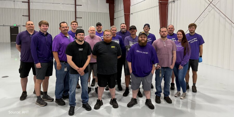
Advanced Heat Treat Corp. (AHT) has completed a building expansion at their Monroe, Michigan facility. The new 6,000 sq. ft. addition increases production capacity and enhances operational efficiency.
The climate-controlled addition will provide an area for additional equipment and services for Advanced Heat Treat Corp. (AHT), free of existing production space, and provide a new office and modern breakroom.
Chad Clark Plant Manager Advanced Heat Treat Corp.
Groundbreaking for the project took place on November 27, 2024 and their certificate of occupancy was awarded on July 29, 2025.
“Seeing this expansion completed is incredibly rewarding—it reflects the hard work and dedication of our entire team,” said Chad Clark, Plant Manager. “The additional space allows us to streamline operations, support more equipment, and enhance service to our customers. We’re excited to begin the transition and fully integrate the new area into our daily workflow.”
Heat Treat Todayreported on a new gas nitriding unit at the Monroe facility last month. The new unit will be utilized in heat treatment for industries such as automotive, government and defense, plastics, power generation, and others. It will utilize UltraGlow® Gas Nitriding, which is a case-hardening process whereby nitrogen is diffused into the surface of a solid ferrous alloy by holding the metal at a suitable temperature in contact with a nitrogenous gas, usually ammonia.
AHT has four locations: one in Monroe, Michigan; two in Waterloo, Iowa; and a fourth in Cullman, Alabama. AHT Michigan has the unique capability to nitride parts up to 31-feet in length.
Press release is available in its original form here.
Founded in 1975, this Mexico-based furnace manufacturer has 50 years of expertise in thermal processing equipment and has delivered more than 2,000 units across 48 countries.Heat Treat Today’sIndustry Company Highlights is dedicated to shining a light on major players within the heat treatment industry.
In today’s edition, learn more about ceramics, proprietary technologies, and technical services that set NUTEC Bickley apart. Read to the end to catcha unique interview of NUTEC Group CEO Daniel Llaguno by Heat Treat Today Publisher Doug Glenn.
With a mission to provide industrial kilns and furnaces to North American and international markets, NUTEC Bickleyis celebrating its 50th anniversary as a company. Through its 50 years of growth NUTEC has made a global impact and continues to look ahead with a vision of wide-reaching impact, including strategies and initiatives which prioritize efficiency in industrial heat treatment.
NUTEC Bickley designs and manufactures kilns for the ceramic industry, furnaces for steel, aluminum and specialty alloys, ovens and dryers, combustion and control systems, and preheaters and dryers. They service the automotive, aerospace, sanitaryware, refractories, abrasives, and steel industries, and are known for their aluminum heat treating furnaces.
The company has several proprietary technologies, including:
ECOmbustion™: An advanced combustion control system that reduces fuel usage and carbon emissions
IMPS™ (Integrated Monitoring & Pulse System): A control technology that enhances process precision and uniformity
Jointless® Insulation Modules: A patented ceramic fiber design that extends furnace lifespan and reduces heat loss
Energy Recovery Systems: Solutions that maximize fuel efficiency by reusing residual heat.
Shuttle kiln Source: NUTEC Bickley
In July 2025, NUTEC Bickley announced an exclusive manufacturing license in North America for Regenerative Thermal Oxidizers through a strategic alliance with Spain-based Kalfrisa. This partnership enhances its environmental technology offerings and expands its North American footprint.
Alberto Cantú, NUTEC Bickley’s vice president of Ceramics and New Business Development, said, “The effective and safe removal of VOCs is vital for a wide range of industries and is something we are asked to address on a regular basis. Kalfrisa is a highly respected name in emissions treatment and control and so I’m delighted that we have been able to announce this new collaborative agreement. There is strong potential for the deployment of high-performance RTOs in the North American market, and I’m very excited about working closely with Kalfrisa to deliver the best available technology.”
The company continues to invest in R&D with recent innovations including a high-precision shuttle kiln for ceramic core sintering and advanced drop-bottom furnaces for aluminum heat treatment. These developments will be featured in upcoming events like UNITECR 2025 in Cancún and the FIA Light Alloy Conference.
Drop bottom furnace Source: NUTEC Bickley
Doug Glenn, publisher at Heat Treat Today, interviewed NUTEC Group CEO Daniel Llaguno for the 50th anniversary of the company and discussed its current operations and future plans.
Daniel Llaguno CEO NUTEC Group Source: NUTEC Group
US Dollar and Pesos (00:01): Daniel discusses how the strength of the U.S. dollar and the Peso relate for the sale of NUTEC’s thermal processing equipment. He shares why “a strong U.S. dollar is very beneficial for us.”
Increasing Capacity at Charlotte Facility to Mitigate Tariffs (3:00): The effects of the current economic and political situation between the United States and Mexico directly impact NUTEC’s business. However, to mitigate tariff impacts, Daniel shares how they are increasing capacity at their Charlotte facility with a goal that 90% of their fiber division production may occur within the United States.
The Path Forward For NUTEC’s Divisions (9:10): NUTEC’s R&D is split across the U.S. and Mexico, and they partner with a research center in Spain; they are pro-active in developing new technologies. Daniel believes that furnaces have to be smarter and more helpful to the client, and the company is geared toward improving efficiency. Daniel adds that NUTEC primarily specializes in customized furnaces.
Inaugurating AI Technologies (13:38): Daniel commented on how NUTEC is in the early stages of exploring applications of AI in their products and business. They currently see many applications on the business side and are actively discerning how to apply it to their furnace technologies.
A company in advanced metal casting technologies has shipped its first commercial additive manufacturing evaporative casting (AMEC) machine to the University of Tennessee, Knoxville (UTK). The system will be installed at UTK’s manufacturing research facility, where it will support continuing education, casting research, and workforce development in next-generation manufacturing.
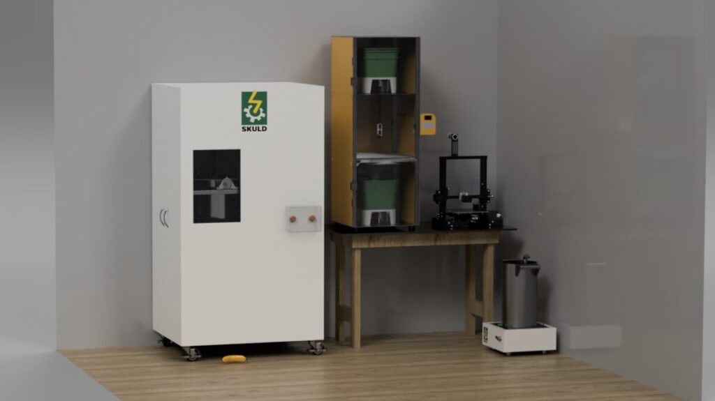
Lightning Metal LM-16 is Skuld LLC‘s flagship machine for additive manufacturing evaporative casting (AMEC). The machine is a tool-less, net-shape casting process capable of producing aerospace grade aluminum and other high-performance alloys with minimal post-processing. The system enables rapid prototyping, reduced lead times, and flexible alloy compatibility, making it ideal for both industrial and academic environments.
The Lightning Metal LM-16 AMEC machine by Skuld Source: Skuld LLCSarah Jordan Founder & CEO Skuld, LLC Source: Author
“This milestone represents…a signal that advanced casting is entering a new era,” said Sarah Jordan, co-founder and chief executive officer at Skuld. “The University of Tennessee is a national leader in manufacturing innovation, and we’re proud to support their mission with a system that bridges research and real-world application.”
Adam Penna Director, Sales and Marketing Skuld Source: Linkedin
UTK will use Lightning Metal LM-16 platform to expand its materials science curriculum, conduct applied research in casting and alloy development, and provide hands-on training for students and professionals entering the manufacturing workforce.
“This is exactly the kind of partnership we envisioned when we launched the Lightning Metal platform,” said Adam J. Penna, director of sales and marketing at Skuld. “It’s a platform that empowers innovation in evaporative casting utilizing 3D printing for improved features like edges and surfaces while also reducing the need for tooling cost…whether you’re solving supply chain challenges or training the next generation of engineers.”
The Technology
Skuld’s AMEC technology merges lost foam with polymer 3D-printing. Heating up to around 2000°F, the machine operates as an automated micro-foundry. The Lightning Metal LM-16 removes the safety issues of handling molten metal and is perfect for small, custom, one-off aluminum parts fasteners. It makes products in a 7″ cube, melting approximately 16lbs of aluminum, and can also process brass or bronze.
The machine is sized to be able to move through standard doorways and utilizes single-phase power, like a dryer plug.
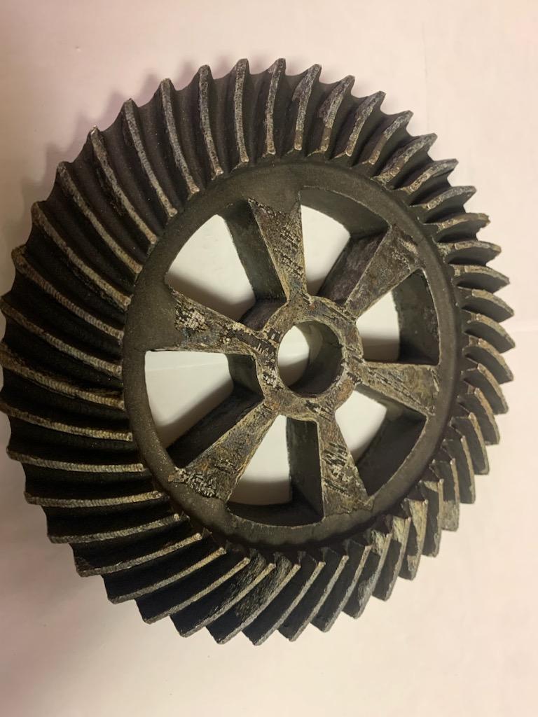
The casting works by utilizing a hollow polymer shape in place of lost foam, where the molten metal vaporizes the polymer. This is a subset of the casting field called lost foam, which is a variation on lost wax investment casting, and eliminates around 90% of process steps, making for fewer costs and a faster process. The mold is insulated with a thin ceramic shell, ceramic beads, a metal container called a flask, and unbonded beads.
Gear produced by Lightning Metal LM-16 Source: Skuld LLCProduct of Lightning Metal LM-16 Source: Skuld LLCProduct of Lightning Metal LM-16 Source: Skuld LLC Source: Skuld LLC
Heat Treat Today asked what difficulties Skuld faced in developing this technology. The development process faced several unique hurdles, such as heat retention due its small size (compared with a large furnace), as well as crafting the machine’s automation while not allowing it to be hackable.
Applications
SBIR awarded to Skuld LLC Source: Skuld LLC
The Lightning Metal LM-16 is for those without an in-house foundry. It works well for replacement parts for in-house heat treatment, for example: hooks, baskets, or rollers. The machine can also produce spare parts or be utilized for prototyping pieces that can be used by higher volume machines. The Lightning Metal LM-16 operates well at around one hundred pieces per year.
The AMEC technology eliminates machining (which reducing costs for clean machining), and drives down the cost substantially associated with cooling for lost foam. The process also avoids HIPing, reducing the need for powder bed fusion parts.
The system enables reverse-engineering for discontinued items, and could be particularly applicable for heavy equipment, agriculture, compressors, and railroads.
The Lightning Metal LM-16 deployment marks a major step in Skuld’s commercialization strategy, following over $9 million in Department of Defense contracts and successful pilot programs with the U.S. Air ForceandDefense Logistics Agency. The company was recently awarded an SBIR for additive manufacturing.
For more information on this technological innovation, please contact Adam Penna at apenna@skuldllc.com.
Atlas Holdings has announced the formation of Orion Steel following the completion of the acquisition of EVRAZ Inc. North America and EVRAZ Inc. NA Canada with their respective subsidiaries. The newly formed Orion Steel will be led by former U.S. Steel executive, Doug Matthews, who will serve as chief executive officer. Orion Steel is poised to become a central player in the North American steel market due to its focus on engineered steel products intended for rail, energy, infrastructure, and industrial.
Atlas announced the agreement in June of 2025 to acquire EVRAZ North America, a leading producer of engineered steel products in the United States and Canada for rail, energy, infrastructure, and industrial end markets. The new company, Orion Steel, includes Rocky Mountain Steel Mills in Pueblo, Colorado; Oregon Steel Mills in Portland, Oregon; and Interpro Pipe and Steel in Regina, Saskatchewan, and locations across Alberta, Canada.
Orion Steel’s website Source: Orion Steel
Collectively, Orion Steel employs 3,400 skilled associates across two electric arc furnace steel facilities, 12 steel product mills, and 17 scrap recycling facilities. They have a steelmaking capacity of 2.3 million tons and a finished steel capacity, including tubular products, of 3.5 million tons. Orion Steel products regularly contain more than 98% recycled scrap material, and Rocky Mountain Steel is the world’s largest solar-powered steel mill and the largest rail supplier in North America.
“As a well-capitalized strategic supplier, Orion Steel is poised to become a central player in the North American market, helping to ensure economic and security interests of the United States and Canada are advanced through significant, local production,” said Doug Matthews, CEO of Orion Steel. “I’ve been in this business for three decades and I am completely energized by this unique opportunity. This is a historic operation heading into a bold new chapter.
“I’ve seen the look in steelworkers’ eyes when they push an operation to new heights. We are going to see that same look from our team members across all Orion Steel facilities as we write the next chapter of this essential North American steelmaker,” added Matthews.
“Doug offers more than just decades of experience in operations, sales, marketing, and supply chain management. He brings a forward-thinking, hands-on approach that helped transform U.S. Steel’s commercial strategy and operations, and he has the deep belief that the heart of this business is the people on the ground, running the mills day in and day out — and he works to empower them to perform at their best.” Atlas Partner Sam Astor commented. “This is a critical time in the global steel market. We’re ready to meet the challenges and seize the opportunities, and we are excited to be playing a role in ensuring the long-term future of strategic steel production in the United States and Canada.”
Matthews began his 33 years with U.S. Steel rising through the ranks from plant leadership in Pittsburgh, Pennsylvania, to operations leadership as a member of the executive team.
Former CEO of EVRAZ, Skip Herald, will continue his service as a member of the Orion Steel Board of Directors.
Press release is available in its original form here.
Whether you need insight on enhancing your energy utilization, managing induction systems (troubleshooting), or prolonging equipment longevity, today’s Technical Tuesday original content feature will keep you well-informed.
Heat TreatToday has coalesced technical information across articles from key experts, including tips to improve your energy efficiency, a walk-through guide for troubleshooting your induction system, and ten practical tips for improving your equipment longevity.
Induction and Sustainability Tips Part 2: Efficient Power
As energy efficiency becomes a driving force in modern heat treating, manufacturers are turning to smarter induction technologies to cut waste and lower costs. In this second installment of Heat Treat Today’s sustainability series, explore how AC-to-DC conversion, intelligent power feedback systems, and advanced diagnostics can transform your induction heating setup into a cleaner, more consistent, and cost-effective process.
“Furthermore, transformers operate at optimal efficiency when under a reduced load – i.e., less than 70% output in steady-state heating – rather than ramping up to the full operating temperature. Another advantage of the DC-type transformer is that its operating power factor is very close to 1.0, which lowers the utility company’s calculation of peak demand surcharges.”
Facing erratic heating, poor consistency, or unexpected shutdowns in your induction system? This comprehensive guide walks heat‑treat operators through a ten‑step diagnostic framework for identifying and resolving common induction issues.
Figure 2. Induction
system components Source: Contour Hardening, Inc.
“The induction process involves many characteristics such as: position of the piece within the induction coil, load positions, cooling positions, cycle times, applied electric power, and others. It is important that the professional can identify the failure and the particular situation at the moment in which it is occurring.
On some occasions, the failures are not evident and therefore it is essential to analyze the part that has been treated. This analysis can be key to understanding situations such as poor depth due to electrical power or decrease in output frequency, among other possible scenarios.”
New and Improved Tips for Induction Equipment Longevity
Heat treaters are always looking for ways to extend the life of their induction tools, but what methods are proven maintenance strategies? Focusing on the durability of coils, bus bars, inductors, and quench components, this technical article will give you practical and reliable tips to promote longevity in your equipment.
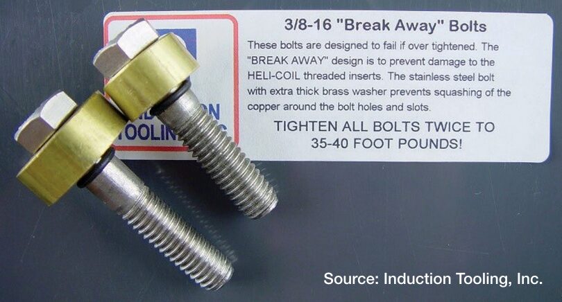
Figure 2. Break-Away bolts designed to fail beneath the washer if over tightened
“More than coils — When working to optimize the life of induction equipment, don’t focus solely on the coils. Bus bars, inductors, and quenching equipment are also key to success.
Austenitic stainless steel — Use austenitic stainless steel for fasteners, fittings, and hose clamps, and remember, non-ferrous is the way to go.
CNC machining — Manufacturing with a 5-axis CNC machine ensures quality and consistency.
“Break-Away” bolts — For fasteners, use “Break-Away” bolts on contact surfaces. These bolts are designed to fail beneath the washer if they are overtightened, a design that prevents damage to the threaded insert inside the copper contact.”
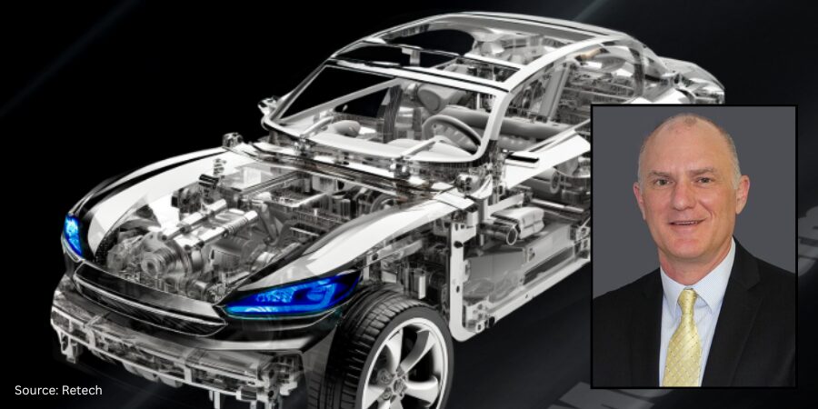
An auto parts manufacturer headquartered in the U.S. is receiving an aluminum chip recycling preparation system. The system will be installed in the plant’s casting house to manage in-house scrap generated from the company’s bank of machining centers.
Earl Good President and Managing Director Retech
Retech, a SECO/WARWICK Group company, will provide this equipment. The chip recycling system features a patented ReMelt Thermofuge® chip dryer.
“Thanks to acquiring the ReMelt company and its know-how we can now offer specialization in material handling, waste processing, and system integration. It allows us to offer an even broader spectrum of metallurgy solutions to our customers,” said president and managing director of Retech, Earl Good.
Traditional thermal dryer systems heat the chips to temperatures that remove both the moisture and the residual oils, which generate considerable volatile organic compounds (VOCs). Alternatively, many casting houses truck their aluminum chips off-site to a 3rd party toll-melter for recycling, but all the additional handling required comes with a variety of costs as well. Retech’s new chip recycling system will only remove the moisture, leaving the oil on the chips. The oil is left to combust in the furnace’s side well, creating an oxygen depleted environment which provides a significant increase in aluminum yields.
The Thermofuge system has its own thermal oxidizer (afterburner) to mitigate any incidental fumes, but because the Thermofuge process has been classified by the EPA to be in a lower risk category compared to traditional thermal dryers, it is subject to far less strenuous regulatory compliance, oversight, and mitigation. The afterburner is equipped to recuperate its waste heat, which is reapplied to preheat the incoming materials, reducing energy consumption and emissions. A traditional thermal dryer could have an annual operating cost of $150k, while a comparable capacity Thermofuge system will cost just $45k per year to operate.
Retech will be customizing the chip dryer to work with the plant’s existing chip conveyor and coolant filtration system.
Press release is available in its original form here.
Welcome toHeat Treat Today’sThis Week in Heat Treat Social Media. We’re looking at a 3D-printed railway station, human rocket rides, a kids summer camp with heat treatment training, and more!
As you know, there is so much content available on the web that it’s next to impossible to sift through all of the articles and posts that flood our inboxes and notifications on a daily basis. So, Heat Treat Today is here to bring you the latest in compelling, inspiring, and entertaining heat treat news from the different social media venues that you’ve just got to see and read!If you have content that everyone has to see, please send the link to editor@heattreattoday.com.
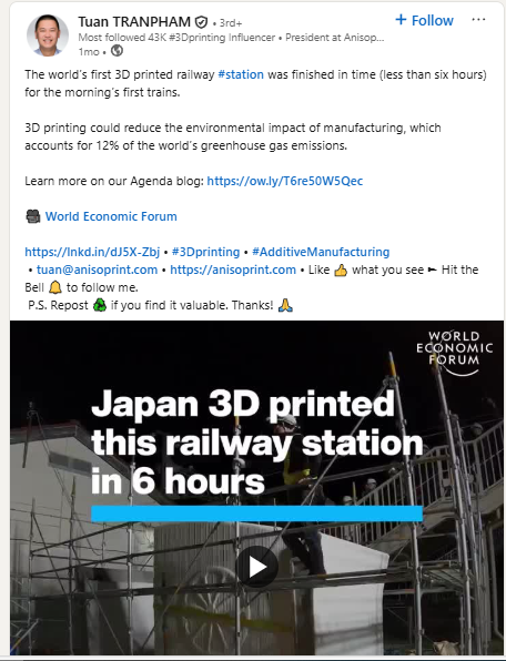
1. You Can Have Your Railway and Print It Too
The world’s first 3D-printed railway station was completed. Additive manufacturing has come a long way, but we are still stunned by its speed! Finished in fewer than six hours, the folks at Anisoprint got it done.
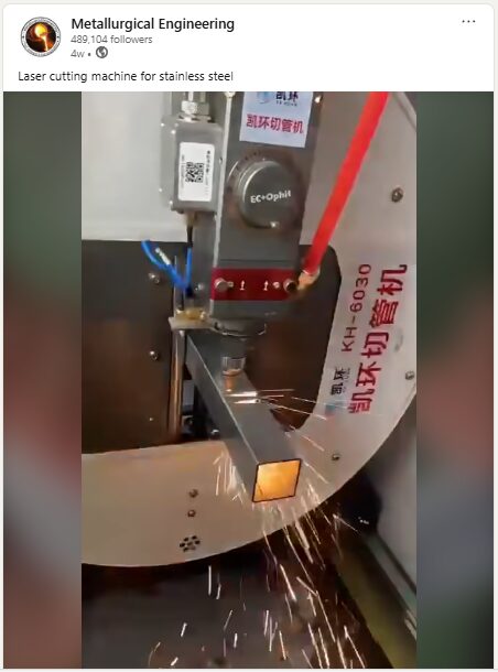
2. Stainless Steel Gets a Haircut
We can’t always articulate why a video is so engaging to watch. This laser-cutting video by Metallurgical Engineering is immensely satisfying. Cozy up with a bag of popcorn and watch the sparks fly!
3. Human Passenger Rocket Flights Are Ongoing
Pluto Aerospace has completed its second successful flight with paid passengers on its Dash prototype, a low-cost hypersonic testbed. Turn on Elton John’s Rocket Man and be inspired to join in the fun.
4. Where High Temp Insulation and Mona Lisa Kiss
Chiz Bros is donating a beautiful piece of art called Bessemer Reflections: Steel in Your Face. That image fittingly reminds us that metal work is both science and craft.
5. Heat Treatment Gets a Taste of Dijon
Dijon, France that is. Our European representative, Hamilton Pearman, recently attended the A3TS Annual Conferenceand Heat Treatments and Surface Engineering Show! A shout out to all of our materials science and thermal processing buffs who also attended!
6. The Summer Camp You Always Wanted
Did you know that Forging Industry Educational and Research Foundation puts on a Forge the Future Summer Camp? You know how we at Heat Treat Today love our Heat Treat Kids, and now we can’t wait to send them off to get their little toes wet in heat treatment.
7. Don’t Slip Past This Leak Detection Resource
From history, to big picture, and practical tips, this Heat TreatRadio has everything you need to stay well-informed.
8. The Furnace is Always On At Heat TreatToday
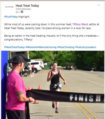
You might think that furnaces and fire would cause enough sweat for our team. But no. They chase it… and win!
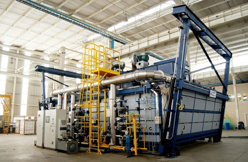
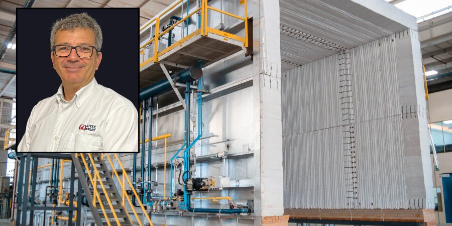
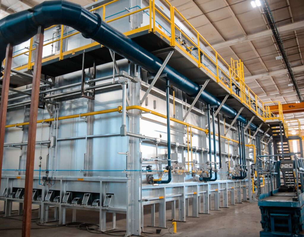
A heat treater in the U.S. Midwest anticipates greater heat treat abilities of ingots with a new gas-fired car bottom furnace. The furnace will be capable of handling both steel and aluminum ingots, with loads up to 150,000lb per cycle.
NUTEC Bickley designed the furnace to operate across a wide temperature range. The high levels of temperature uniformity to be delivered by the combustion system mean that this furnace will be qualified to undertake AMS2750 compliant surveys.
Arturo Arechavaleta, NUTEC Bickley’s vice president of Metal Furnaces, said: “Our customer for this important project has been serving the industry with a dedicated heat treat facility for many decades, and is a widely recognized and trusted name in steel and aluminum circles.”
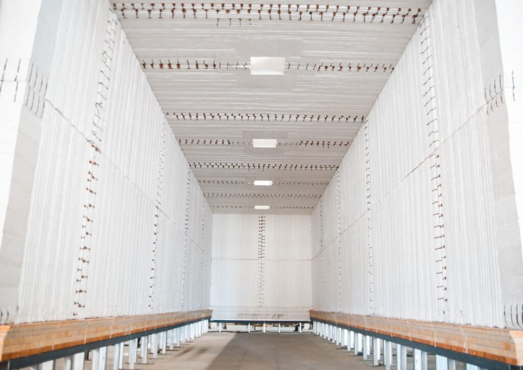
The working dimensions of the furnace are 12ft w. by 35ft l. by 14ft 6in h. Normal operational temperatures range between 300°F (150°C) and 1650°F (900°C), with a maximum of 2000°F (1095°C). With burners firing above and below the load, there are 11 automatic control zones (five top, six bottom). The optimum approach to heat treat these heavy loads is pulse firing with variable excess air.
The furnace uses high-velocity nozzle-mix burners in a staggered configuration to fire above and below the load, maximizing heat transfer and providing optimum temperature uniformity. One of the IMPS® (Integrated Multizone Pulsing System) modes is Excess Air Firing. Among other things, it allows control over very low temperature while high turbulence is maintained to achieve temperature distribution.
In the Ratio Firing mode, the air and gas valves pulse in a synchronized pattern, from low to high fire in stoichiometric ratio, to ensure optimal fuel efficiency. This is made possible by using the kinetic energy generated by the flame speed and the rapid transition from low to high fire which increases entrainment and turbulence, thus promoting a better temperature distribution without the need for a high level of excess air.
Press release is available in its original form here.
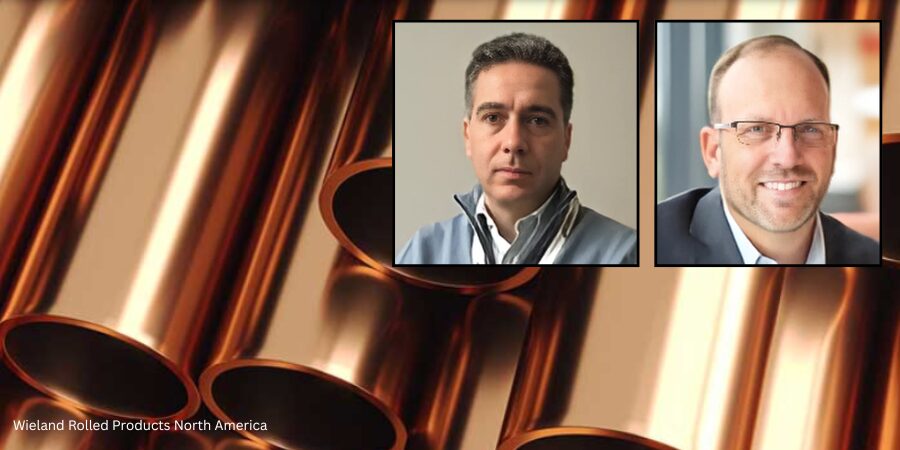
A new reheating walking hearth furnace has been commissioned for Wieland Rolled Products North America. The new furnace has a processing capacity of up to 110 metric tons per hour and will support Wieland’s expansion plans in the production of high-grade copper products.
Greg Keown President Wieland Rolling & Recycling Source: Tenova
Wieland Rolled Products North America was delivered the furnace by Tenova, which is integrated with a selective catalytic reduction (SCR) deNOx emissions control system. The equipment will enable Wieland to expand the production of high-grade copper products, essential for several key industrial sectors. This installation is a key element of Wieland’s broader investment to upgrade and expand its East Alton, Illinois facility.
“We are pleased to continue our collaboration with Tenova as we enter the next phases of this expansion project. Their technology and project management expertise are expected to support our production goals and sustainability efforts,” said Greg Keown, president of Wieland Rolling & Recycling.
Francesco Memoli remarked, “This project is particularly meaningful for us because it integrates advanced combustion and fume treatment technologies to meet both performance and environmental targets. It’s a clear example of how we tailor heat treatment solutions to the unique requirements of non-ferrous production.”
Francesco Memoli President & CEO Tenova Inc. Source: Tenova
The furnace, engineered by Tenova Italimpianti, has a processing capacity of up to 110 metric tons per hour. Powered by a natural gas combustion system, it features Tenova’s proprietary TR Flat Flame Roof burners equipped with integrated recuperators and post-combustors. The configuration ensures a substantial 90% reduction in NOx emissions. This technology has already delivered positive environmental performance in both reheating and heat treatment applications.
Wieland’s expansion project includes a new hot rolling mill designed to increase production capacity for copper and copper alloy components used in electric vehicles (EVs), EV charging networks, and renewable energy systems.
Press release is available in its original form here.
In this Technical Tuesday installment featuring Combustion Corner by Jim Roberts, president of U.S. Ignition, readers are enlightened about how upcoming policies might impact their burner systems, fuel mixtures, and equipment. Could certain policies impact technical requirements of heat treating? Find out more below.
This informative piece was first released inHeat Treat Today’sJuly 2025 Super Brands print edition.
A furnace guy goes into a bar and says, “This looks like a fast crowd… and all the players nod in agreement.”
Where are we? It’s the future! And in heat treating and combustion circles, the changes that will occur in the next several years will be very impactful to our industry. We’ve all heard these things, and we have some of the very best experts in the world working for us in this industry to make sure that we continue to grow and to be a leader in the legislation and rules that could cripple the wonderful world of heat treating and metals.
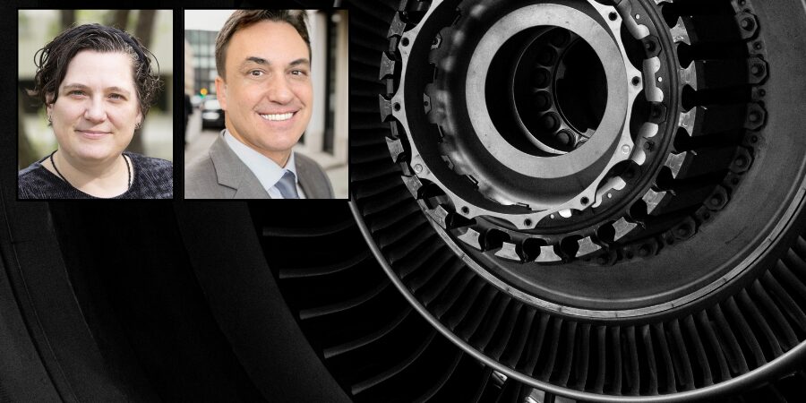
We are lucky to have industry associates at the Metal Treating Institute (MTI)who understand the impact of some of these new regulations. In this year’s Air & Atmosphere issue of Heat Treat Today magazine, Michael Mouilleseaux (Erie Steel LTD) provided updates on the proposed decarbonization initiatives. I have seen presentations by Michael and his committee composed of Heather Falcone (Cook Induction Heating Company) and Ben Gasbarre (Gasbarre Thermal Processing Systems). This is critical knowledge for us all, and we should be staying as vigilant and supportive as we can. Michael’s interview is a must-read in that February issue – if you missed it, go back and read it. Please.
And then you say, “What’s this got to do with combustion equipment and the stuff that this Roberts guy is normally talking about?”
Well, not only does the decarbonization mandate mean the possibility of costs through government burdens and penalties, but the equipment and process change requirements are going to be staggering if we don’t prepare.
As long as I’m in a name-dropping mood, I’m going to mention Brian Kelly of Honeywell. Brian is a degreed aerospace engineer, and yet he decided to come play in the mud with us furnace guys for a career. Brian has several detailed presentations online about some of the prime initiatives for all the combustion equipment companies — hydrogen Combustion. Yep, the “H” word. The holy grail of zero pollution. One of those presentations includes fascinating detailed data on hydrogen and other emission initiatives, given by Brian Kelly and Todd Ellerton on YouTube regarding future combustion technology requirements.
“So, what does the “three times faster” thing mean, Jim?”
Well, all major combustion equipment companies, like Honeywell, understand that hydrogen requires three times the amount of fuel to generate the same amount of available heat as natural gas. Hydrogen also burns with seven to eight times the “flame speed” of natural gas. It burns, on average, about 400 degrees hotter (F) than natural gas. And so, from an engineering standpoint, there are a fantastic number of variations that must be considered as we look forward, especially when addressing CO₂ and other emissions. Add propane, butane, methane, producer gas, landfill gas, and anything else that is presently being utilized in the heat treat circles, and that provides a lot of possible variations!
Now, it needs to be said that a good many burners can burn hydrogen already. The anticipation of this level of scientific and ecological requirements was seen a long time ago. Conversely, many cannot. Brian Kelly explains that 17% of the present pre-mix/blended fuel systems cannot utilize this fuel. It also bears mentioning that there are three different grades of hydrogen production levels.
So, let’s start doing the math on how many iterations it will take. But here is the biggest tidbit of hydrogen science in the combustion world – hydrogen is the smallest molecule and the lightest in a molecular sense. Helium is smaller and lighter, for fact-checker purposes, but we aren’t trying to burn helium, are we? So, as we blend hydrogen with our other fuels (i.e., the most practical way to maintain some of the infrastructure and equipment), we need to have our combination equipment suppliers test and verify that which exists will work.
Obviously, if it takes three times the fuel volume, existing gas delivery lines will be an issue. At the molecular level, smaller and lighter means that many existing seals, connections, and control valves may no longer be gas-tight and may leak. That’s not good! If the flame speed of these fuels is five to eight times that of existing fuels, temperature profiles within the process will need to be reviewed and re-calibrated. And if it burns 400 to 500 degrees hotter, certainly that will require a review of the former materials of construction.
So, how does this tie into the original theme of “The future is coming fast?” Well, we have just touched briefly on one possible fuel transition that is on the horizon. Carbon points/credits are already being taxed in Europe. We can bet that these global decarbonization efforts will be moving ahead. We will need a review so that a “head in the sand” mentality does not catch any of us in the thermal processing community flatfooted and ill-prepared.
It’s easy to think that it won’t affect you. When I mentioned “three times as fast,” of course, I was alluding to the fuel references, and the best way to be prepared for the future is to see it coming. Be alert and stay current, and we will adapt as an industry, as we have so many times before. Until next time …
About The Author:
Jim Roberts President US Ignition
Jim Roberts president at U.S. Ignition, began his 45-year career in the burner and heat recovery industry focused on heat treating specifically in 1979. He worked for and helped start up WB Combustion in Hales Corners, Wisconsin. In 1985 he joined Eclipse Engineering in Rockford, IL, specializing in heat treating-related combustion equipment/burners. Inducted into the American Gas Association’s Hall of Flame for service in training gas company field managers, Jim is a former president of MTI and has contributed to countless seminars on fuel reduction and combustion-related practices.
For more information: Contact Jim Roberts at jim@usignition.com.