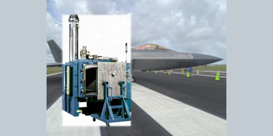
A defense industry manufacturer has purchased an inert atmosphere batch oven for processing stainless steel parts in a reduced oxygen environment to prevent scaling. The furnace is designed to use a nitrogen atmosphere system to reduce surface oxidation of parts and includes a flow meter calibrated for nitrogen and controlled via closed loop to maintain the reduced oxygen level.
Wisconsin OvenCorporation shipped the system, which has a maximum temperature rating of 1,250°F with the capacity to heat and cool approximately 6,000 lbs. of steel per load in an inert atmosphere. The temperature is controlled by a Watlow F4T digital recorder/controller with ethernet communication capabilities. Temperature uniformity of +/- 10°F at 1,000°F and 1,200°F was verified with a nine-point profile test.
Mike Grande Vice President of Sales Wisconsin Oven Corporation Source: Wisconsin Oven Corporation
The oven features a “CAN” style construction with a heavy plate exterior, a total of six inches of insulation, and an 18-gauge 304 stainless steel interior. To maximize throughput and productivity, the oven is designed with a pneumatically operated vertical lift door and powered load/unload table capable of handling up to 6,000 lbs., along with a water cooling system to reduce the cooling time, to allow for faster production cycles.
“This inert atmosphere oven includes several state-of-the-art features that increase production throughput and provide reduced surface oxidation,” said Mike Grande, vice president of sales at Wisconsin Oven. “These include water cooling to reduce the cooling time at the end of the cycle, closed-loop nitrogen control to prevent nitrogen overconsumption, oxygen and humidity sensors to provide real time data, and an industrial IoT system to connect the unit to the Wisconsin Oven aftermarket team for remote data monitoring and tech support.”
The press release is available in its original form here.
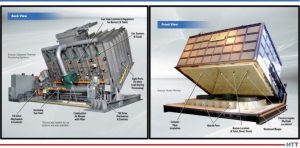
Consider the numerous systems in your heat treat operations. What makes up the anatomy of each furnace? In this "Anatomy of a Furnace" series, industry experts indicate the main features of a specific heat treatment system. For this inaugural feature, note how the schematics demonstrate how the tip-up furnace is able to process massive loads in an atmospheric sealed environment at highly controlled temperatures.
Contact us with your Reader Feedback!
Annotations for this furnace corpus were provided by Dan Herring, The Heat Treat Doctor®, The HERRING GROUP, Inc. A front view of a tip-up furnace as well as a back view of a different tip-up are provided along with the labels.
Download the full graphics by clicking the images below.
Click to download now!
This Technical Tuesday article is drawn from Heat Treat Today's February's Air & Atmosphere Furnace Systems print edition.
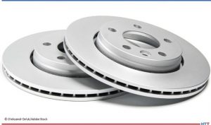
Are your brake rotors heat treated? Travel back in time to discover how ferritic nitrocarburizing (FNC) became the heat treatment of choice for automakers’ brake rotors and why the tip-up furnace forever altered the production process for this part.
This Technical Tuesday article is drawn from Heat Treat Today's February Air & Atmosphere Furnace Systems print edition.If you have any information of your own about heat treating brake rotors, our editors would be interested in sharing it online at www.heattreattoday.com. Email Bethany Leone at bethany@heattreattoday.com with your own ideas!
The Problem: Brake Rotor Corrosion
Michael Mouilleseaux General Manager at Erie Steel, Ltd. Sourced from the author
In the early 2000s, corrosion was one of the top three issues that U.S. automotive manufacturers found negatively affected the perception of the quality of their cars. Brake rotors are made of cast iron. These components sit out in the elements, and in places like the U.S. Midwest where salt is often used on the roads, unprotected steel or iron will corrode or rust. Even on the coast, there is salt water in the air.
Contact us with your Reader Feedback!
What does rusting cause? The rotor rusts, and first, the cosmetics are negatively affected (i.e., rusty appearance). But more importantly, the first time you step on the brakes, it squeals like a pig, the vehicle shudders, and the driver feels pulsing in the pedal. He’ll also feel it in the steering wheel because the amount of rust coating one area is different from the amount of rust that’s on another. So, these brand new, forty- to seventy-thousand-dollar cars have orange rust over the brake rotor and a shaky drive. . . it’s not a good look!
Now, this is just a superficial coating of rust that will eventually abrade away; the rotor will look alright, the vehicle will stop better, and it won’t squeal. However, since the rust on the rotor wears off unevenly, the car may never have smooth braking.
A Move to FNC
In the early 2000s, all the big players were looking to FNC (ferritic nitrocarburizing) as a solution to corrosion, including Bosch Braking Systems, Ford, General Motors, Akebono, and the truck manufacturers. FNC was becoming popular since the process adds a metallurgical layer — called the “white layer” or “compound zone” — to the part, providing corrosion resistance and the bonus of improving wear.
Source: Oleksandr Delyk/Adobe Stock
To the OEMs, the benefits were perceived as:
The corrosion issue had an answer.
The life of the rotor doubled from roughly 40,000 to 80,000 miles. Although that meant half as many aftermarket brake jobs compared to before, consumers perceived it as a real advantage.
The rotors generated less dust. Brakes generate dust particles as the result of abrasion of the pads and the rotors. This particulate dust has been identified as both an environmental and a health concern. Now, flash forward to 2022: Electric vehicles are largely displacing the need to control emissions from ICE (internal combustion engine) vehicles. So, the new European standard on vehicle emissions implemented a requirement to control this dust that is harmful to the environment and which EV and traditional brake systems can emit.
But there were certain technical and practical challenges that automotive manufacturers faced when trying to implement this process at scale.
#1 Distortion. Brake rotors may distort during FNC. Since rotors are (gray iron) castings, the process temperature for FNC may stress relieve the rotor, causing it to change shape or distort, rendering it unusable as a disc brake rotor. It was determined that if the rotor castings were stress relieved prior to machining and FNC, the distortion issue was rendered moot.
#2 Loss of Necessary Friction. FNC gives the white layer on the surface of a part with a diffusion zone underneath. The compound zone has a very low coefficient of friction, which means excellent wear properties. However, manufacturers want friction between the rotor and the brake pads to slow the car down. Reducing the friction on the rotors extends the braking distance of the car.
". . .[M]anufacturers want friction between the rotor and the brake pads to slow the car down." Source: Unsplash.com/Craig MorolfLet me illustrate this: I ferritic nitrocarburized a set of brake discs for Bosch Braking Systems, which eventually went to Germany and then on a vehicle. The customer absolutely loved the corrosion resistance, but when it was time for the downhill brake test, the car went straight through an instrument house because the brakes couldn’t stop the car! Lesson: For rotors treated with FNC, the brake pads need to be made from a different frictional material!
#3 Cost. Overcoming the technical issues is simple. Stress relieving the casting at FNC temperatures before machining it would help the parts machine better and would eliminate distortion. Modifying the FNC process could reduce the depth of the white layer and, paired with the correct friction material, the acceptable braking capabilities were restored. Yet these additional steps presented a new challenge: higher costs.
The practical constraints of FNC in conventional batch or pit furnaces strained efforts to be cost-effective. The load (size) capacity of the conventional equipment, in conjunction with the time constraints of the FNC process presented a dilemma, as the OEMs’ benchmark was about one dollar per rotor.
Here Comes the Tip-Up
With traditional furnaces for FNC, there was just no way to reach the economics that were necessary for it. A bigger pit furnace might be the way to go, but they really weren’t big enough. So, here comes the tip-up.
Traditionally, a tip-up furnace has been used for processes with just air, no atmosphere. With direct fired burners, the furnace is used for tempering, stress relieving, annealing, and normalizing. Everything loads into the box, gets fired, and unloads, similar to a car-bottom furnace. With the appropriate external handling systems parts could be retrieved from the furnace and then quenched. This additional process increased the usefulness of the equipment and allowed for the processing of tubes, bars, big castings. . . big forgings for the oil industry and the like.
The question of how to heat treat brake rotors on a large scale still needed to be answered. It required a large, tightly sealed furnace with atmospheric integrity for excellent temperature uniformity. In ferritic nitrocarburizing, the processing range is about 950°F to 1050°F. It is well known that properties vary significantly across the temperature range. And they needed to be optimized to create the appropriate frictional properties for the rotors.
So, the answer was: Let’s make a tip-up furnace that can be sealed for atmospheric integrity, has the appropriate temperature uniformity, and can circulate gas evenly. A lot of this would have to be iterative — create, test, compare, repeat.
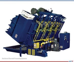
Tip-up furnace from Gasbarre Thermal Processing Systems Source: Gasbarre Thermal Processing Systems
The development of the perfect tip-up was essentially the work of one furnace manufacturer and one heat treater who together changed the industry.
American Knowhow Makes the Perfect Tip-Up
In the early 2000s, heat treaters worked with OEMs to develop a cost-efficient process in a tip-up. Manufacturers and service providers tested different methods, including atmosphere FNC and salt bath FNC.
By 2009, the perfect atmosphere furnace was complete and high volume brake rotors began to be processed for General Motors. The furnace manufacturer was JL Becker, Co., acquired by Gasbarre in 2011. The commercial heat treater was Woodworth, Inc., located in Flint, MI. Together, they spent a lot of time and money looking into FNC and figuring out how to make it work in a tip-up furnace.
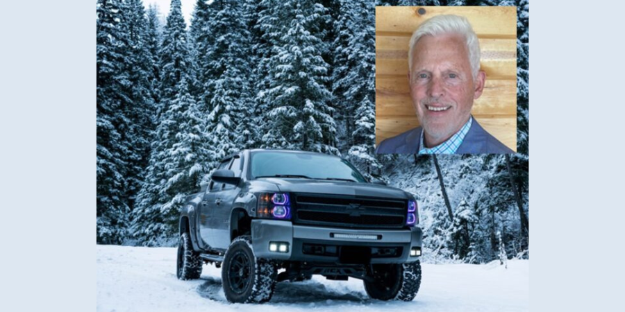
General Motors was the first one to get on board, utilizing the FNC processed rotors on their pickup trucks and big SUVs, like the Escalade and Tahoe. Ford was not far behind using it on their F150 pickup truck. I was shocked the first time I saw the commercial: a Silverado pickup truck, out in the snow, and the speaker saying, “We now have an 80,000-mile brake system because of a heat treating process called FNC!”
It’s a great story of American knowhow and a collaborative effort between someone who saw a need and someone else who saw the way. To this day, if you want to get a replacement set of brake rotors for your car, go to a place like AutoZone; they will tell you that the difference in cost between the OEM parts and an off-brand is the fact that the off-brand is not heat treated.
About the author: Michael Mouilleseaux has been at Erie Steel, Ltd. in Toledo, OH, since 2006 with previous metallurgical experience at New Process Gear in Syracuse, NY, and as the Director of Technology in Marketing at FPM Heat Treating LLC in Elk Grove, IL. Having graduated from the University of Michigan with a degree in Metallurgical Engineering, Michael has proved his expertise in the fi eld of heat treat, co-presenting at the Heat Treat 2019 show and currently serving on the Board of Trustees at the Metal Treating Institute.
Let’s discover new tricks and old tips on how to best serve air and atmosphere furnace systems. In this series, Heat Treat Today compiles top tips from experts around the industry for optimal furnace maintenance, inspection, combustion, data recording, testing, and more. Part 4, today's tips, examines carbon probes and carbon control. Look back to Part 1 here for tips on seals and leaks, Part 2 here for burners and combustion tips, and Part 3 here for data and record keeping tips.
This Technical Tuesday article is compiled from tips in Heat Treat Today's February Air & Atmosphere Furnace Systems print edition. If you have any tips of your own about air and atmosphere furnaces, our editors would be interested in sharing them online at www.heattreattoday.com. Email Bethany Leone at bethany@heattreattoday.com with your own ideas!
1. Slight Positive Pressures Are Best
Contact us with your Reader Feedback!
Atmosphere furnace pressure should be only slightly above ambient. The range should be between 0.25-0.35 inches water column. Higher pressures in multiple zone pusher furnaces will cause carbon control issues. High pressures in batch furnaces will cause high swings when doors and elevators move.
If you’re having atmosphere problems with a furnace that has been operating normally for some time, avoid the temptation to remove the carbon probe. There are several tests you can run on nearly all carbon probes while the probe is still in the furnace, at temperature, in a reducing atmosphere. Super Systems Inc. provides an 11-step diagnostic procedure in a white paper on their website, in a paper titled, “Carbon Sensor Troubleshooting” by Stephen Thompson.
"Review process date for abnormalities." Source: Super Systems Inc.
Many factors can contribute to why parts are not meeting the correct hardness readings. According to Super Systems Inc., here is a quick checklist of how to start narrowing down the culprit:
Review process data for abnormalities. The first thing to do is make sure the parts were exposed to the right recipe. Check the recorders to make sure the temperature prof le and atmosphere composition were correct. Make sure all fans and baffes were working correctly. Determine if any zones were out of scope and that quench times were acceptable. If any red flags appear, hunt down the culprit to see if it may have contributed to soft parts.
Check the generator. Next, check the generator to make sure it is producing the gas composition desired for the process. If available, check the recorders to make sure the gas composition was on target. If not, check the generator inputs and then the internal workings of the generator.
Check the furnace atmosphere. If the generator appears to be working correctly, the next step would be to check the furnace itself for atmosphere leaks. Depending on what type of furnace you have, common leak points will vary; for continuous furnaces, common leak points are a door, fan, T/C, or atmosphere inlet seals. Other sources of atmosphere contamination may be leaking water cooling lines in water-cooled jackets or water-cooled bearings. More than likely, if the generator is providing the correct atmosphere but parts are still soft, there is a leak into the furnace. This will often be accompanied by discolored parts.
Check carbon controller to make sure it matches furnace atmosphere reading (verify probe accuracy and adjust carbon controller). This can be done using a number of different methods: dew point, shim stock, carbon bar, three gas analysis, coil (resistance), etc. Each of these methods provides a verification of the furnace atmosphere which can be compared to the reading on the carbon controller. If the atmosphere on the carbon controller is higher than the reading on the alternate atmosphere check, that would indicate the amount of carbon available to the parts is not as perceived. The COF/PF on the carbon controller should be modified to adjust the carbon controller reading to the appropriate carbon atmosphere. If the reading is way off, it may require the probe to be replaced.
Maciej Korecki Vice President of Business of the Vacuum Furnace Segment SECO/WARWICK
An industrial automation manufacturer has ordered a heat treatment system to establish a captive hardening plant within their machine park. The line of two vacuum furnaces, an atmosphere furnace, and a washer will harden and carburize parts, specifically gears, pinions, and shafts.
SECO/WARWICK, a manufacturer with North American locations, will produce the furnaces to harden and vacuum carburize the elements used in motor reducer production. These parts figure in the automation applications production process for industries such as automotive, aviation, food and printing.
“In these times of constant problems with maintaining the supply chain, having captive heat treatment within a machine park provides our partners with a huge competitive advantage and independence," says Maciej Korecki, vice president of the Vacuum Furnaces Segmentat SECO/WARWICK Group. "Within a relatively small area, we can create a heat treatment system that will meet the Partner’s needs."
Find heat treating products and services when you search on Heat Treat Buyers Guide.com
A tooling manufacturer is expanding with an electrically heated, steam atmosphere pit furnace for steam treating parts. The steam treating process creates a uniform blue-black finish on the surface of parts, which improves wear and corrosion resistance.
Lindberg/MPH, a manufacturer based in Michigan, shipped the steam treating furnace which has a maximum temperature rating of 1,250°F and work chamber dimensions of 22" diameter x 36" depth. The pit furnace is insulated with vacuum formed ceramic fiber modules that allow for rapid heat up rates and fast control response. A circulation fan distributes heat evenly throughout the chamber which ensures rapid and uniform heat transfer throughout the product load.
“This steam atmosphere pit furnace has the sufficient capacity to process a workload of 1,200 lbs," comments Kelley Shreve, application engineering manager at Lindberg/MPH. "This furnace was also designed with a custom powered lid for ease of loading."
Find heat treating products and services when you search on Heat Treat Buyers Guide.com
A heat treat furnace has been delivered to a Midwest manufacturer of ceramic matrix parts. This system will be used for aerospace and military purposes.
Atmosphere-Controlled Retort-Burn Off Furnace Source: L&L Special Furnace Company, Inc.
Ceramic matrix parts materialize when nanofibers of silicon carbide or other ceramic nano threads are wound together, forming various sheets and 3D-printed shapes. The nano threads in the process are coated with proprietary resins that must be completely removed from the substructure using heat. The resulting finished product is lighter and stronger than titanium.
L&L Special Furnace Company, Inc.'s Model XLC3672 has a work zone of 32” wide by 32” high by 66” deep. It has a single zone of control with a temperature gradient of ±20°F at 1,100°F using four zones of temperature control with biasing to balance any temperature gradients. The Model XLC3672 is controlled by a Eurotherm Nanodac Mini 8 program mechanism with overtemperature protection.
Find heat treating products and services when you search on Heat Treat Buyers Guide.com