A Connecticut producer of precision metal components plans to relocate its manufacturing operations to a significantly larger facility in Southington, Connecticut in early 2019.
Economy Spring, whose current facility is pictured here, plans relocation to larger facility.
Economy Spring, an MW Industries company, announced that this expansion is fueled by the rapid growth of Economy Spring’s coiled springs, wire forms, and product assemblies sold to customers in medical and pharmaceutical applications. The new 216,000 square foot facility will be over twice the footprint of the existing Southington facility. Equipment will be moved in various stages during 2018 and 2019 with no expected operational impact to customers.
The company manufactures a broad range of medical and pharmaceutical products such as but not limited to surgical staples, hypodermic needles, and implantable titanium products.
“Economy Spring’s growth means we need more space to meet future customer demand. By selecting a facility just a mile down the road, we expect complete retention of our committed, technical, and highly experienced workforce,” explained Tim Thompson, senior vice president and general manager of Economy Spring. “Our transition plans include building finished goods inventory and communicating closely with customers to ensure a seamless transition.”
Induction Hardening Tips: Equipment Selection for Scan Hardening, Part 2
This is the second installment of a multi-part column on equipment selection for induction heat treatment. Part 1, Dr. Valery Rudnev On . . . Induction Hardening Tips: Equipment Selection for Scan Hardening, covered types of scanners, scan hardening system setup, quenching challenges, maximizing process flexibility, and computer modeling. In this installment, Dr. Valery Rudnev discusses another critical aspect of induction scan hardening: inductor design subtleties and a comparison of different fabrication techniques (brazing vs. CNC
machining vs. 3D printing).
Introduction
Hardening inductors are often considered the weakest link in an induction hardening system because they may carry significant electrical power and operate in harsh environments exposed to high temperatures, water, and other coolants while being subjected to mechanical movement and potential sudden part contact.
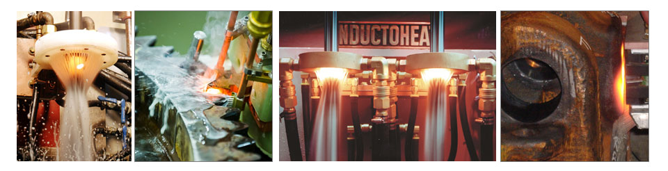
Single-turn or multiturn inductors may be used in scan hardening (Figure 1). Copper profiling and the number of turns is determined by the workpiece geometry, required hardness pattern, and the ability to properly load match the coil to the power supply without reaching the operational limits or by other specific process requirements, such as the production rate or the hardness pattern runout/pattern cutoff. [1]
Figure 1: Single-turn or multiturn inductors may be used in scan hardening.
The longer (in case of horizontal arrangement) or the higher (vertical arrangement) the scan coil is, the faster the scan rate can be. This is due to the simple fact that the longer inductor leads to a longer period when the part will be inside the coil; therefore, the scan rate can be greater. However, limitations on the maximum length of the inductor’s heating face may be associated with the maximum permissible runout.
Hardness Pattern Runout Control
Single-turn inductors with narrow heating faces (3mm-6mm wide) are used where a sharp pattern runout is needed. An example of this would be the case where a pattern must end near a snap ring groove. Inductors with wider heating faces or two-turn coils can be used when a faster scan rate is desired and an extended runout is permitted. The main disadvantage to the excessively wide heating face is that it may result in an unspecified shift of coil current density when hardening complex geometric parts due to an electromagnetic proximity effect. [1]
Inductor Fabrication Techniques
In applications where high process repeatability is critical (including automotive, aerospace, defense and other industries), the great majority of scan hardening inductors are CNC machined from a solid copper block, thus making them rigid, durable, and repeatable. CAD/CAM/CNC software programs are created that provide appropriate cutter-to-copper spatial relationships, which produce inductors of the required shape and precision regardless of complexity. Figure 2 shows a variety of finished and semi-finished CNC-machined hardening inductors. [2]
Figure 2: finished and semi-finished CNC-machined hardening inductors
In other cases, copper tubing (square, rectangular, round, or die-formed shaped tubes) may be used for coil fabrication (Figure 3). Copper tubing is typically annealed to improve its ductility, bending properties, and workability. When sharp bends or complex coil shapes are required, inductor segments made from tubing are assembled by brazing. Joints are often overlapped, creating tongue-and-groove joints. Butt-joints should not be used.
Figure 3: Copper tubing (square, rectangular, round, or die-formed shaped tubes) may be used for coil fabrication.
A complex geometry inductor that contains numerous brazed joints, and elbow-type 90° joints in particular, could experience impeded water flow in the cooling coil turns, shortening coil life. Poor quality brazed joints are prime candidates for water leaks affecting not only the coil life expectancy but also a quality of hardened components due to a potential soft spotting in the areas of water leaks. Eliminating braze joints or dramatically reducing their number, particularly in current-carrying areas, is the key to fabricating durable, reliable, and long-last inductors.
Additive manufacturing (AM), or 3D printing, delivers successful fabrication of fixtures, tooling, holders, etc. Recently, some inductors have been fabricated using 3D printing as well. It is important to keep in mind that AM is not a single technology but it comprises a number of processes including direct metal laser sintering, electron beam melting, directed energy deposition, direct and indirect binder jetting, and others.
Depending upon a particular AM technique used in fabricating hardening inductors, it may face major challenges to match properties of pure copper. This includes (1) obtaining sufficiently high thermal conductivity (2) or low electrical resistivity, (3) ensuring high volumetric density, and (4) having minimum amount of residuals, just to name a few. All these factors affect coil life. Therefore, if you compare 3D printed inductors with brazed coils comprising numerous brazed joints, in the majority of cases, the life of 3D printed coils will surpass life of brazed inductors because of elimination of brazed joints in current-carrying regions. In addition, fabrication accuracy and repeatability of AM inductors typically surpasses the accuracy of brazed or bended coils.
The situation is different when comparing life of 3D printed coils vs. CNC machined inductors. Fabrication accuracy of both processes is very similar, however, in high-power density applications even small degradation of above discussed four factors associated with AM might become essential causing greater probability of stress-fatigue and stress-corrosion copper failure of 3D printed coils compared to CNC machined inductors fabricated from pure copper. Another factor to consider is repairability of 3D printed inductors. If you need to do a revision then it would be most likely required you to re-manufacture 3D printed coils. Regardless of a fabrication method and for quality assurance purposes, it is beneficial to apply computerized 3D metrology laser scanner technology (Figure 4) to verify coil dimensional accuracy and alignment precision after inductor fabrication and assembly.
Figure 4: It may be beneficial to apply computerized 3D metrology laser scanner technology to verify accuracy and alignment after inductor fabrication and assembly.
Material Selection
Copper and copper alloys are almost exclusively used to fabricate induction coils due to their reasonable cost, availability, and a unique combination of electrical, thermal, and mechanical properties. Proper selection of copper grade and its purity is crucial to minimize the deleterious effects of factors that contribute to premature coil failure including stress-corrosion and stress-fatigue cracking, galvanic corrosion, copper erosion, pitting, overheating, and work hardening. Cooling water pH also affects copper susceptibility to cracking.
Oxygen-free high-conductivity (OFHC) copper should be specified for most hardening inductors. In addition to superior electrical and thermal properties, OFHC copper dramatically reduces the risk of hydrogen embrittlement and developing localized “hot” and “cold” spots. The higher ductility of OFHC copper is also important because coil turns are subjected to flexing due to electromagnetic forces. The higher cost of OFHC copper is offset by improved life expectancy of hardening inductor.
For scan inductors that are intended to heat fillets, an appropriate copper heating face region must be focused into the fillet area. Coil copper profiling and the use of flux concentrators (flux intensifiers) are beneficial to focus the magnetic field into the fillet. These applications require careful design because the induced current has a tendency to take the shortest path and stay in the shaft area rather than flowing into the fillet [1]. Therefore, all efforts must be made to focus the heat generation into the fillet. Typically, higher frequencies work better for this purpose.
Copper Wall Thickness
It is important to maintain sufficient wall thickness to carry the electrical currents. The wall thickness of an inductor’s heating face should increase as frequency decreases. This fact is directly related to both the current penetration depth in the copper δCu. [1] It is highly desirable for the current-carrying copper wall thickness to be 1.6 times greater than the δCu calculated at maximum working temperature. Increased kilowatt losses in the copper, which are associated with reduced coil electrical efficiency and greater water-cooling requirements, will occur if the wall is thinner than 1.6∙δCu.
The table below shows the variation of δCu vs. frequency at room temperature (20°C/68°F).
In some cases, the copper wall thickness can be noticeably thicker than the recommended value of 1.6∙δCu. This is because it may be mechanically impractical to use a tubing wall thickness of, for example, 0.25 mm (0.01 in.).
I recommend Reference #1 to readers interested in further discussion on design of hardening inductors.
Dr. Valery Rudnev, FASM, is the Director of Science & Technology, Inductoheat Inc., and a co-author of Handbook of Induction Heating (2nd ed.), along with Don Loveless and Raymond L. Cook. The Handbook of Induction Heating, 2nd ed., is published by CRC Press. For more information click here.
A global provider of industrial furnace controls and process automation solutions announced a new collaboration with a leading industrial gas company that combines the core competencies of each company into a comprehensive offering for heat treatment customers. Praxair Inc is based in Danbury, Connecticut, and produces and distributes atmospheric, process, and specialty gases and high-performance surface coatings. Customers will have access to Praxair’s gases, application technologies, and supply systems, along with United Process Control Inc’s portfolio of specialized industrial flow measurement and atmosphere control products. This continues the long-standing relationship between Praxair and Atmosphere Engineering Company, now a member of UPC, based in West Chester, Ohio.
The combined capabilities of the two companies will bring more end-to-end technologies for a broad spectrum of batch and continuous heat-treating processes such as carburizing, carbonitriding, neutral hardening, annealing, gas quenching, and heat-treatment applications under vacuum processing.
“The automotive and aerospace industries continue to expand requirements for heat treating,” said Steve Mueller, Praxair’s Associate Director of Business Development for Metals and Materials Processing. “We have a team approach in place, combining Praxair’s process know-how and expertise in industrial gases with United Process Controls’ specialized products. Together we meet customers’ requirements for high-quality heat treating with reproducible standards in their furnace operations.”
“This strategic agreement with Praxair reflects our commitment to offer the heat-treating industry a complementary and evolving portfolio of innovative technologies that help drive process efficiency and reliability. We look forward to working closely with Praxair in the coming years, as we strive to further increase our presence in North America,” said Paul Oleszkiewicz, President, UPC.
Heat Treat Todayoffers News Chatter, a feature highlighting representative moves, transactions, and kudos from around the industry.
Personnel and Company Chatter
Arathi Krishna has been appointed managing director of Sumdram Fasteners Ltd, based in Chennai, India, as her father and manufacturing veteran Suresh Krishna retires. However, Suresh Krishna will continue to be the director and non-executive chairman of the global auto components maker. Arathi Krishna has been the joint managing director of the company since 2011 and has been on the Board since 2006.
ASM International recently announced that William J. Lenling and Masahiro Fukumotohave been selected to become members of the 2018 Thermal Spray Hall of Fame by the ASM Thermal Spray Society Board of Directors. “Mr. Lenlingis a co-founder (1992) and CTO of TST Engineered Coatings in Sun Prairie, Wisconsin, which engineers and manufactures industrial coatings and coated components. The award citation reads: For sustained achievements in entrepreneurial advances of thermal spray processes and proven leadership in establishing state-of-the-art production processes and high value in-situ quality monitoring manufacturing practices. Dr. Fukumotois a professor of mechanical engineering at Toyohashi University of Technology in Japan. Award citation: For significant contributions to the development of thermal spray technology through innovative research, published papers, and leadership in TSS and Asian thermal spray societies.” (ASM)
UK-based Wallwork Cambridge, which supplies heat treatment, engineering, castings and vacuum equipment to the aerospace sector, has secured Rolls-Royce’s seal of approval for vacuum brazing, plasma nitriding, and heat treatment. With the installation of a vacuum brazing furnace and two new plasma nitriders, the company is more than doubling the nitriding capacity at Cambridge, enabling versatility and quicker processing of aerospace components.
Brandon Sheldon, a project manager based at Plibrico Refractory Construction‘s Salem, Ohio office, recently received his API 936 Refractory Personnel Certification from the American Petroleum Institute (API). The industry certification program certifies knowledge of API STD 936 Refractory Installation Quality Control Guidelines for field testing of monolithic refractory materials, as well as installation and repair of refractory linings. In addition, the certification program helps to align the company’s installation teams with third-party inspection services to facilitate improved quality assurance practices overall.
Solar Atmospheres, Inc., in Souderton, PA, recently installed a 74″ diameter by 72″ deep horizontal internal quench vacuum furnace, designed by Solar Manufacturing, Inc., to quench with argon at 10-bar while utilizing a 600 horsepower motor running at 460 volts from a variable speed drive, and rear head moveable gas baffle doors. The goal of the massive quench system is to be able to quench larger batches of power generation castings by increasing the cooling rate and eliminating the supplemental use of helium and operating in 100% argon.
An electrically heated cyclone pit furnace was recently delivered by Lindberg/MPH to a steel heat treater to be used for a heat treating process on aircraft components. The maximum temperature rating for this electric pit furnace is 1250ºF. The work chamber has a 38″ diameter x 48″ depth and is constructed with an alloy liner backed with 7″ of block insulation.
Spanish supplier of aluminum sheets and coils Aludium has announced that the company will install a multi-chamber furnace to reduce metal costs and improve the sustainability of its operations. The new furnace will be installed in the Amorebieta cast house and will increase Aludium’s ability to melt lacquered scrap and is due to come onstream during 2019. The multi-chamber furnace selected is a Hertwich Ecomelt PS275, a proven technology and one of the largest shaft furnaces in the world.
Solar Atmospheres, Inc., installs internal quench vacuum furnace
Lindberg/MPH delivers cyclone pit furnace
Aludium installs multi-chamber furnace
Kudos Chatter
Proudly presenting the certificates are (l-r) Director Georg Anzer, Managing Partner Renate Keinath and Head of Training Michael Vieth.
PyroGenesis Canada Inc. has announced that it has received certification for the production of metal powders under a quality management system which complies with the requirements of ISO 9001:2008. This certification is an amendment to the company’s existing ISO certification, pertains specifically to metal powder production, and was received under the auspices of a major independent risk and standards company, SAI Global.
Family-owned global manufacturer of plastic processing machines Arburg, based in Loßburg, Germany, has recently been presented three certifications: LQW, ISO, and IHK recognition. The LQW certificate was presented to the machine manufacturer in January after the successful completion of the “Learner-oriented Quality Certification in Continuing Education and Training”. The company received the approval of DIN ISO 29990:2010 “Quality Management Systems for Learning services for Non-formal Education and Training” inspection in February. In late 2017, the manufacturer was recognized with the “1A Excellent Training Company” award presented by the Chamber of Industry and Commerce (IHK) – Northern Black Forest region.
Countyline Tool, a Komet Service Partner based in East Peoria, Illinois, has attained ISO 9001:2015 certification. All Komet partners are currently working to obtain the ISO 9001:2015 certification, and Countyline Tool is the eighth partner to have completed the certification.
Heat Treat Today is pleased to join in the announcements of growth and achievement throughout the industry by highlighting them here on our News Chatter page. Please send any information you feel may be of interest to manufacturers with in-house heat treat departments especially in the aerospace, automotive, medical, and energy sectors to the editor at editor@heattreattoday.com.
A major Quebec steel producer recently announced that investments of nearly CAD$70 million (US$54.2 million) will include replacing heat treatment equipment at two locations.
François Perras, chief executive officer, ArcelorMittal Long Products Canada
ArcelorMittal Long Products Canada will replace two reheating furnaces at its Contrecoeur-East wire rod mill and its Contrecoeur-West bar mill. These new furnaces, which aim to increase the company’s rolling capacity by 100,000 tons, will enable greater productivity, optimal energy use, and reduced greenhouse gas emissions. The work should extend until the first half of 2020.
“We are renewing ArcelorMittal’s commitment to Quebec,” said François Perras, chief executive officer, ArcelorMittal Long Products Canada. “Our choice to invest in the acquisition of high-performance equipment will help us accelerate our move towards high-value-added steel production, particularly for the automotive and construction industries.”
The largest U.S. steel producer and “mini-mill” steelmaker recently announced plans to build a rebar micro mill near Frostproof, Florida, in a bid to capitalize on the growing demand for construction steel. The facility will produce steel rebar from scrap metal.
Charlotte-based Nucor Corporation will invest $240 million in the steel plant in Florida. The company began construction on its second rebar micro mill project in Sedalia, Missouri, in November 2017.
“Nucor has always focused on growing our business to better serve our customers. We are building this rebar micro mill in a great and growing market where demand is strong and there is currently an abundant supply of scrap, a good portion of which is handled by our scrap business,” said John Ferriola, chairman, CEO & president of Nucor Corporation. “Consistent with our planned strategy of being a low-cost producer, this micro mill will give us a cost advantage over our competitors who are shipping rebar into the region from long distances.”
The rebar micro mill, which will produce steel rebar from scrap metal, is expected to have an estimated annual capacity of 350,000 tons.
Dave Sumoski, executive vice president of Merchant and Rebar Products
“We would like to thank the many state and local officials, leaders, and partners who have assisted us with the project,” said Dave Sumoski, executive vice president of Merchant and Rebar Products. “Identifying the right location is an essential part of our rebar micro mill strategy, and this part of central Florida met all the criteria we evaluate. We look forward to becoming a member of the community.”
An agreement to bring high-performance differentials and differential technologies from the premium market to the general market of passenger cars, light trucks, crossovers, SUVs was recently finalized between an American driveline and powertrain technologies engineering and manufacturing firm and a German supplier to premium European-based automakers.
Alberto Satine, President AAM Driveline
The expanded relationship between American Axle & Manufacturing, Inc. (AAM), which serves automotive, commercial, and industrial markets, and Drexler Automotive GmbH, which manufactures high-performance limited slip differentials, racing transmissions, drive shafts, and wheel hub systems, immediately integrates electro-mechanical limited slip differentials (eLSDs) into the AAM TracRite family of differential products. These systems greatly improve vehicle handling and traction for all-wheel drive or rear-wheel drive vehicles. The system, used extensively in high-performance vehicles from premium OEMs, provides active torque control of the wheels by translating vehicle torque requests into accurate axle torque response.
“AAM and Drexler are partnering to offer the market mature differential technology that will allow the general driver new levels of excitement by taking handling and traction to new levels of performance,” said Alberto Satine, President AAM Driveline. “Combining AAM and Drexler’s design, engineering and manufacturing expertise will provide our customers with the highest-quality, most-advanced driveline systems.”
The system’s power-dense, four-pinion differential design supports axle modularity with open and eLSD differentials in the smallest packaging space. Additionally, the scalable clutch, actuation, and differential design of the technology drives a wide range of applications and vehicle segments.
Herbert Drexler, Drexler Automotive Founder
“AAM’s global scale and high-volume manufacturing capability make the company the perfect partner for Drexler,” said Herbert Drexler, Drexler Automotive Founder. “We look forward to engineering and developing differentials that meet the needs of our global OEM customers.”
TracRite Electro-Mechanical eLSD will go into production later this year.
This is the fifth in a series of articles by AMS2750 expert, Jason Schulze (Conrad Kacsik). Click here to see a listing of all of Jason’s articles on Heat Treat Today. In this article, Jason advances the discussion of TUSs with a lesson on the definitions of key AMS2750E terms. Please submit your AMS2750 questions for Jason to editor@heattreattoday.com.
Introduction
When executing a technical process, understanding the meaning and intent of certain definitions can clarify the interpretation of certain requirements, thereby, altering a specific course based on that interpretation.
In this article, we will focus on the primary definitions associated with temperature uniformity surveys as they apply to AMS2750E.
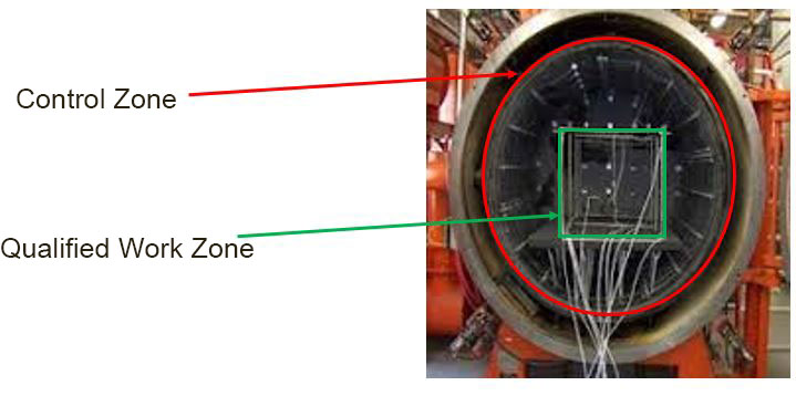
Control Zone vs Qualified Work Zone
Control Zone
AMS2750E, page 44, para 2.2.9: “A portion of the work zone in thermal processing equipment having a separate sensor/instrument/heat input or output mechanism to control its temperature. This portion of a furnace is independently controlled.”
Qualified Work Zone
AMS2750E, page 6, para 2.2.42: “The defined portion of a furnace volume where temperature variation conforms to the required uniformity tolerance.”
It’s important to understand the difference between the two definitions. Below is a figure which outlines the most basic idea behind each.
Figure 1
Failure of a Survey Thermocouple
AMS2750E, page 4, para 2.2.19: “Obviously incorrect or erratic activity of a survey thermocouple indicated by extreme high readings, extreme low readings, and/or erratic changes in readings not reflected by other sensors.”
This situation can be observed by pyrometry technicians in real time as the survey is running. Possible reasons for this may be:
a loss in chrome due to vapor pressure (vacuum furnaces only),
movement of the thermocouple during the test from the documented position,
Polarity reversal during test thermocouple assembly.
Note that AMS2750E allows only a specific number of thermocouples to fail during a TUS (see AMS2750E, page 30, para 3.5.16).
Heat Sink
AMS2750E, page 5, para 2.2.24: “A mass of material equivalent to the heat transfer characteristics of the thinnest section of the part being heat-treated. Heat sinks may be used during TUS (3.5.10.1) and during production (3.3.5).”
The use of heat sinks during a TUS is optional. Operators are permitted to utilize heat sinks on both TUS test thermocouples and the load thermocouple being used. The key is to document the initial TUS load condition, including the use of heat sinks, and utilize this configuration on subsequent tests.
If heat sinks are utilized on either the TUS test thermocouples, or the load thermocouples, the heat sink must comply with AMS2750E, page 26, para 3.5.10. Additional requirements and clarification regarding heat sink requirements can be found in the Nadcap Pyrometry Guide on page 47, question #43 and Heat Treat Auditor Advisory 17-007.
Figure 2
Qualified Operating Temperature Range
AMS2750E, page 6, para 2.2.41: “The temperature range of thermal processing equipment where temperature uniformity has been tested and found to be within required tolerances as specified in 3.3”
This temperature range affects multiple aspects of pyrometry, including the instrument calibration setpoints of both furnace instruments (AMS2750E page 14, para 3.2.5.5.1) as well as field test instruments (AMS2750E, page 14, para 3.2.5.4) used on that particular equipment. It also affects what product can be heat treated in the particular furnace.
Field Test Instrument
AMS2750E, page 4, para 2.2.20: “An instrument that is portable, that meets the requirements of Table 3, has calibration traceable to secondary equipment or better and is used to conduct on-site tests of thermal processing equipment.”
One of the key points in this definition is the term “portable”. This implies that furnace instruments cannot be used as field test instruments. For those new to pyrometry, this may cause confusion as a single instrument make and model could be designated as a field test instrument or a furnace instrument. As an example, consider a Yokogawa DX model electronic recorder. A supplier could buy two of the same model and use one as a furnace recorder and the other as a TUS recorder (making it a field test instrument). The only differences are its designated use, calibration points, and the fact that is independent from the furnace (portable).
Field test instruments must be calibrated using a standard instrument or better at 6 points per AMS2750E, page 14, para 3.2.5 and have an accuracy of ±1°F or 0.1%, whichever is greater.
Temperature Uniformity
AMS2750E, page 7, para 2.2.66: “The temperature variation (usually expressed as ± degrees) within the qualified furnace work zone with respect to set point temperature. For retort furnaces where a sensor in the retort is used to control temperature, the temperature variation is with respect to the sensor in the retort and not to the furnace set temperature.”
This relates directly to the furnace class designation per Figure 2 of AMS2750E. It’s important to keep in mind question #21 of the Hwhen designating furnace class.
Temperature Uniformity Survey
AMS2750E, page 7, para 2.2.68: “A test or series of tests where calibrated field test instrumentation and sensors are used to measure temperature variation within the qualified furnace work zone prior to and after thermal stabilization.”
As any pyrometry technician knows, one of the main issues to watch for is thermal inertia, or overshoot. Any overshoot will be cause for immediate failure and initiation of an internal RCCA per AMS2750E, page 34, para 4.2.
Conclusion
Understanding AMS2750E definitions will be advantageous to readers of the remaining articles in this TUS series.
We will next discuss the differences between periodic surveys, initials surveys and more.
Submit Your Questions
Please feel free to submit your questions and I will answer appropriately in future articles. Send your questions to editor@heattreattoday.com.
An Italian metal additive manufacturer recently installed two furnaces and dedicated a new department exclusively to heat treating in a bid to expand its heat treatment capability and maximize the performance of aluminum alloys.
On-site training for induction heating system operation is being offered for individuals and small groups that will bring new employees up to speed in safe system operations, effective setup, and preventative maintenance. Instruction for advanced operators are also available.
Eldec LLC will provide hands-on training at their facilities in Auburn Hills, Michigan, or in any company shop.
Trainees learn:
How to safely operate the system.
How to setup for the best productivity and smooth operation.
How to maintain the system to prevent costly break downs.