An HTT consultant on Hardide A coating technology . . .
“The technology behind using advanced tungsten carbide coatings for metal parts, as described in this article, looks very promising, and in my estimation bears further investigation. The stereotypical misgiving with coatings, irrespective of the method of deposition [i.e. PVD, CVD] is that although they improve wear and corrosion resistance, they result in marginally decreased fatigue life. This technology would appear to answer the fatigue life portion of this question; however, this article really does not speak to the corrosion/wear resistance properties of the process.” ~ Michael Mouilleseaux, General Manager, Erie Steel Ltd.
Air Europa Airbus A330-202
A UK-based provider of advanced tungsten carbide coatings for metal parts recently announced that its tungsten carbide/tungsten metal matrix composite coating has been selected as the replacement for hard chrome plating (HCP) on Airbus A330 compression flap pads.
Following this announcement, Hardide Coatings, which also has a facility in Martinsville, Virginia, for processing parts for customers in North America, received word from an independent testing source that Hardide-A tungsten carbide/tungsten metal matrix composite coating improves the fatigue life of metal components by 4.5% when compared to uncoated substrates. The tests were conducted by Westmoreland Mechanical Testing and Research Ltd (WMTR), a leading aerospace qualified testing laboratory in the UK and USA, concluding also that Hardide-A eliminates the need for costly secondary shot peening, making the coating a significant advancement in materials optimization for the aerospace and other industries where fatigue debit of surface-coated metals is a problem.
WMTR used the rotating bend fatigue test method complying with BS ISO 1143:2010. This test is considered to be the most sensitive to the effects of surface treatment on fatigue properties. Samples of S99 steel were coated with Hardide-A to a thickness of 63-70 microns and hardness of ~950 Vickers, which are mid-value thickness and hardness properties for this coating type. The test was discontinued after 15 million cycles.
Traditionally, the fatigue debit after hard coatings such as hard chrome plating (HCP) and HVOF coatings have been applied can be as much as 60% and only following shot peening of the coated surface can this be reduced to around a 20% debit. The Hardide-A coating recorded a fatigue life increase of +4.5% after coating without any need for shot peening. The Wöhler S-N curve for the coated samples is clearly positioned above the uncoated control samples’ curve by ~40 MPa throughout the whole range of the N cycles to failure.
Dr. Yuri Zhuk, technical director at Hardide Coatings
Fatigue debit of surface-coated metals has been a long-standing problem for the aerospace industry; Hardide-A was developed specifically to meet the needs of the sector. This environmentally compliant and technically superior replacement for HCP and HVOF coatings provides enhanced protection against corrosion and chemically aggressive media, wear, galling, fretting, and fatigue.
“Metal fatigue is an enduring problem in aerospace as well as for the steam and industrial gas turbines industries, and we recognized the value in commissioning independent testing to verify the fatigue advantages of Hardide-A,” said Dr. Yuri Zhuk, technical director at Hardide Coatings. “The positive 4.5% improvement to fatigue life provides the detailed analysis and assurance that our solution is an improved alternative to traditional HCP and HVOF coatings. Unlike these other coatings, Hardide-A has no through micro-porosity, so creating an excellent barrier against corrosion as well as improving fatigue performance.”
Welcome to another episode of Heat Treat Radio, a periodic podcast where Heat Treat Radio host, Doug Glenn, discusses cutting-edge topics with industry-leading personalities. Below, you can either listen to the podcast by clicking on the audio play button, or you can read an edited version of the transcript. To see a complete list of other Heat Treat Radioepisodes, click here.
Audio: James Jan & Andrew Martin on Development of Modeling Software
In this conversation, Heat Treat Radio host, Doug Glenn, publisher of Heat TreatToday, interviews Ford Motor Company’s James Jan about Ford’s cooperation with AVL on the development of modeling software to help predict and avoid cracking on aluminum cylinder heads. Andrew Martin from AVL also joins the conversation with what exactly it is they did with Ford.
Click the play button below to listen.
Transcript: James Jan & Andrew Martin on Development of Modeling Software
The following transcript has been edited for your reading enjoyment.
Mr. James Jan, Ford Motor Company (JJ): My name is James Jan. I graduated from the University of Michigan in Ann Arbor, and I have a Ph.D. in mechanical engineering and during my Ph.D. studies, I focused on multiphase flow. Basically it is the full mechanics but we deal with multiple phases—usually it is a mixture of liquid and gas. I graduated in 1994 and I’ve been working with industry, the automotive industry, to be more specific, since my graduation. I have worked in the auto industry for 20+ years, since 1994. However, I’ve been involved in quite a few different subjects in my career even though they are all sensor or fluid mechanics, spent three years writing software (which is also a CFD software), and I work on the intake exhaust manifold and work on the local problems. I was pulled into Ford for this current project back in 2011. That was the time I got very heavily involved in the development of the heat treat process. Before that CFD, but after that it’s about heat treat.
Doug Glenn, Heat Treat Radio (DG): As Mr. Jan says, he is now heavily involved with heat treat, specifically on modeling of the quenching process for aluminum cylinder heads. I asked Mr. Jan to explain the issue that Ford was having. But before he describes the situation, it is important for you to know that Ford was addressing this issue long before nearly all other car manufacturers and is, in fact, a leader in industry with regard to resolving this highly technical heat treat and product design situation. Here is how Mr. Jan describes the situation that set the ball rolling nearly 20 years ago at Ford.
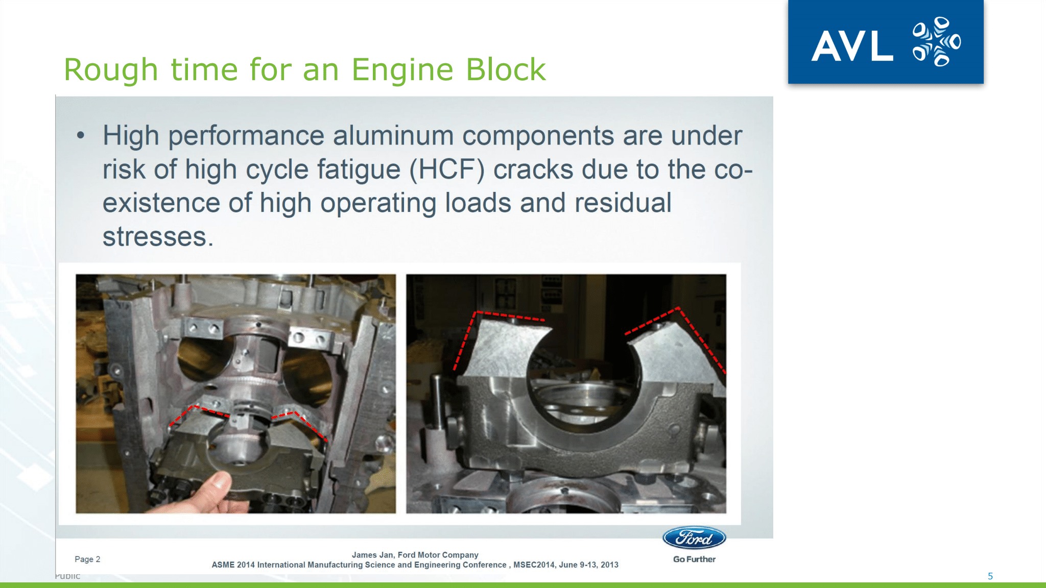
Structural failure in valve bridge area
JJ: The reason that they wanted to solve the problem is because during the heat treat process there are a lot of cracks. The cracking problem during heat treating has been a quality concern for Ford for many, many years. I would say that the problem has been there for 20 some years. In the past, during the cracking process, one of the remedies would be to do a lot of trial and error. For example, during water quench if they see a crack, they switch to air, and if the air doesn’t work, then they switch to polymer. Or if this is cracking somewhere or in some location, they add more material in that area. So, it’s pretty much like responding to the problem, rather than trying to understand the problem and to predict the problem. So that is where the whole thing comes in that the researchers started the project in 2002 because they believe that they really needed a tool to predict the problem rather than responding to it.
DG: So, the problem Ford was having was decades old. And it is a problem that many manufacturers have. It is the age-old problem of being able to predict residual stresses formed during the quenching process that ultimately result in cracking and component failures. Ford, like many other manufacturers, were simply doing trial and error until they got the right combination of part geography, heat treat cycle, and quenching medium and quench orientation. The problem is, that process takes a long, long time and it costs a huge amount of money. Here is Mr. Jan describing the issue with a trial and error approach.
JJ: Every time they make a change to a design, they have to build a prototype part. There will be cost involved because when you build the prototype, you still need a die, you still need the testing process, and then once you have built it you have to run the test to see if it cracks or not. This back and forth just simply takes too much time and too much cost.
DG: The thinking was that if the design engineer and manufacturing engineer could talk earlier in the process, it would help save time and money. Specifically, it would be better if the design engineer could interact with some sort of predictive modeling system that fairly accurately represented the heat treating and quenching portion of the manufacturing process to predict residual stresses and potential cracking issues before they happened. If that were possible, it would save Ford thousands if not hundreds of thousands of dollars. Here is Mr. Jan describing the idea.
JJ: This has something to do with the product development process. When any company tries to development product, their first objective is to satisfy the functional requirement. So basically, if you have an engine and you want a certain horsepower, you want to make sure your engine will satisfy the horsepower. At the beginning of design, their only concern is about functionality, they don’t care about anything else. Once the design is fixed, somebody needs to make it. I belong to manufacturing engineering, so we do not deal with designing, we deal with how to make that part.
During the design process, they usually do not have manufacturing information. Once the design is done, which is usually pretty late in the design cycle, the part has pretty much been determined already. Then we come to manufacturing and we try to quench it, and find, “Oh, gee, it’s cracked.” Then we tell product development, “We have a cracking problem,” and they say, “I wish you had told me earlier.” That is where the problem comes in. Because we are not able to know if the process works or not until we have a physical part, so that’s why Ford’s research tried to initiate a project that said even though design is still ongoing and the manufacturing generally has not started yet, let’s try to do some virtual process simulations to see whether it will crack or not.
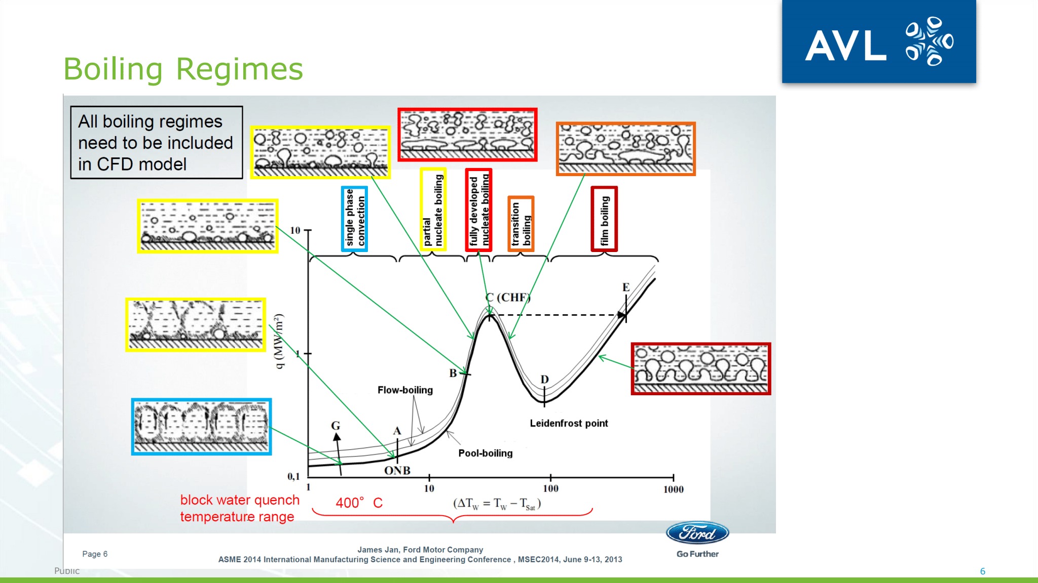
DG: The specific tool that Ford was looking for was a tool that could predict multiphase flow quenching outcomes, what many of our listeners would recognize as the Leidenfrost Effect or vapor boiling. According to Mr. Jan:
JJ: The boiling process, because the physics is very complicated, we couldn’t find any commercial software on the market that would solve the problem. So, we contacted AVL at the time.
DG: As Mr. Jan said, since they weren’t able to find any commercially available software to predict the multiphase Leidenfrost Effect, they turned to AVL. So, Heat TreatRadio put a call into AVL Powertrain Engineering in Plymouth, Michigan, and spoke with Andrew Martin, who is the direct of advanced simulation technologies. We asked him about AVL’s relationship with Ford.
Andrew Martin, AVL (AM): Our relationship has gone back to about 20 years now. Twenty years ago, Ford was seeing cracking in the cylinder heads—and not only Ford but many of its competitors out in the marketplace. So, this was something they wanted to explore. AVL as a company, currently at about 10,000 engineers, has always had a strong relationship with Ford. We develop engines and transmissions together, and things like that. Ford came to us and asked can you look into this? They knew that we had a good CFD code and we were doing a lot of multiphase work, especially on things like fuel injection and boiling in water jackets and things like that. They knew we had a reputation in those areas, so they wanted to work with us on coming up with some sort of a simulation and analysis approach for the boiling that occurs during quenching analysis. Between us, we did the research and that led to a technical paper that was published, I think ASME, but that was in 2002. James (Jan) was involved in that paper back then as well.
DG: I asked Andrew to briefly describe the cylinder head issue that Ford brought to them.
AM: Cylinder heads are very complicated because they have so many cavities. When you quench something like that, then the vapor gets trapped in certain areas and that can lead then to localized residual stresses.
DG: And what did AVL have to bring to the table?
Boiling regimes
AM: Previously, they were doing it the old-fashioned way, they were doing with thermocouples. They would thermocouple a cylinder head and quench it and then look at the data and get the HTCs (heat transfer coefficients) from it then feed that back into the CFD code and then make some assessments about the residual stresses and the distortion. But that is a very expensive way of doing it and it doesn’t lend itself very well as a designing tool. They wanted to find some mathematical approach for doing that. James is extremely experienced in CFD and has used a whole bunch of our CFD codes that compete with AVL FIRE. But he then started using FIRE and realizing that given all the tools that he had at his disposal, FIRE was the one that was giving the best results for doing this boiling analysis.
DG: Andrew referred to AVL FIRE which is a brand name of a specific product offered by AVL. I asked him to briefly explain that product.
AM: AVL FIRE is a CFD (computational fluid dynamics) code. It is an engineering discipline that is quite common and quite popular. We then used CFD to model the boiling that goes within a tank of water and the interface between the component and the water, the so-called film boiling barrier. We model what happens with FIRE CFD code, we model what is happening at the transition of the interface between the metal component and the water. Because when something that hot gets plunged into water, it is quite an interesting thing that happens—it is called the Leidenfrost Effect. Initially, what happens is the component is so hot, it forms a film around the outside of it, a vapor film, and perversely that vapor film then insulates the component from the water. That film slowly breaks down then you get into nucleate boiling and things like that, and that becomes a lot more aggressive and the cooling happens much faster until you eventually get a single phase. But actually modeling the boiling process is what the CFD code does. That is the secret sauce that we’re bringing to the party here.
DG: And, in fact, this secret sauce that Andrew refers to is quite unique. Earlier, James Jan from Ford mentioned that the AVL model was able to handle multiphase analysis, where most other models simply ignored one of the phases, usually gas, and focused exclusively on the interaction between the hot metal and water. I asked Andrew to unpack this more sophisticated modeling process and what developments have been made since they initially started working with Ford.
AM: Since then, it’s matured a lot further within the software. We now have different meshing approaches and we’ve also moved beyond water as well, of course. A lot of quenching is done in water, but there is also a lot of gas quenching, so blown air quenching, which takes longer but is less aggressive. And then we’ve got into steels as well. The original work we did with James was more on aluminum and that doesn’t have the same phase transformation issues as steel does. So
Typical simulation results
we’ve done a lot more work with steel recently, where we have to take account of that latent heat, that then forms a sort of a knee in the cooling, so we then model that. When we doing steel, of course, we’re using oil more commonly, so then we have different properties of oil to consider, different fluid properties of that. Most recently and what has been very interesting, we’ve been involved with a Canadian casting company on spray quenching. There you have a mix
between blown air and actually liquid itself where we’re spraying a jet of fluid at the component. Mathematically, that is a heck of a lot more complicated because you have to model the spray and you have to model the Ledienfrost Effect and the cooling and so on.
DG: Given the solution that AVL brought to Ford, I was curious if both Ford and both AVL were happy with the partnership. First, James Jan from Ford on how Ford and AVL worked together to develop the tool.
JJ: As a matter of fact, even though AVL worked with us to provide us the technology, it is not like we just go buy it and use it.
Simulation variables
Actually, we worked together about 3 to 4 years. On our end, we provided a lot of testing data because we work with a university and we also have an experiment facility inside Ford. When they provided the tool to us, it is still like a banana. They have the basic formulation working but they haven’t tested or validated, so there are 3 to 4 years where we were actually working like partners. It is not like, ok, I’m going to Home Depot, buy a tool and come home and use it. No. We actually did not put the AVL tool into production use until 2015. So there was about 3 to 4 years of time going back and forth trying to improve software. Until today, we still own a small piece of the technology, that is proprietary to our company Ford. Even though to AVL and buy their software and they bring it home, they may not produce the same results that we do, because we have a secret recipe in Ford.
AM: We’ve been very happy with the willingness of Ford to develop the process further, to mature it. They saw that we had something that was useful and beneficial and brought value, but actually James has been phenomenal, because he’s really pushed that agenda as well, and written papers and taken it to conferences, and I think he’s been very impressed with what AVL FIRE has been able to do, so he will talk to anybody about it. So we love it.
DG: Finally, I asked Andrew Martin from AVL who, in his estimation, would also benefit from the AVL fire and similar products, and what changes are being made for the future.
AM: It’s casting companies for sure. I was talking to a British company that makes castings, like high-end blocks for Astin Martins and Land Rovers and so on, and they have certain specifications they have to meet. They are not allowed to have a residual stress more than a certain level in a certain direction. Now how do they know that that’s the case? They can actually cast a few and then heat treat them and then cut them up and see how the material releases, but that rather destroys the actual component in the first place. So companies like that that want to know where are the residual stresses in the component and they want that as something that they can certify the component for, it is very good for that sort of company. Automotive is an obvious candidate, but also we’ve been doing a lot more work in aerospace where the residual stresses that they do want to know where are they and how much are they. Things like landing gears and stuff like that.
DG: And how about the future?
AM: Well, our software is developed over in Europe. I talked to Dr. David Greif the product manager the other day asking him where are we going with this. We’re making it a lot more easy to use. We’re putting workflows in place in AVL FIRE that sort of lead the user through the steps needed to predict the residual stresses and so on. The meshing of the components got a lot simpler using this polymeshing and it more leads you by the hand, as opposed to being a general purpose CFD code where you’ve got to build your own methodology to start off with. FIRE has a methodology built in for doing quenching and that’s brilliant. We’re doing a lot of work with gears at the moment. We’re working with a vacuum furnace company in Wisconsin called ECM Group and they’ve been using AVL FIRE for predicting the residual stresses in the components, so we’ve got a great relationship with ECM and that’s taking us in different directions as well. They are especially doing work on the gear side, so that’s been interesting.
DG: In fact, the whole relationship between Ford and AVL is interesting, as well as the ability to bridge the gap between design and heat treatment. Specifically, the quenching part of heat treatment. With advances in technology and modeling packages like AVL’s FIRE, high volume producers like Ford and other automotive, as well as aerospace manufacturers, have the opportunity to save significant dollars by modeling the process before they jump into the manufacturing process with both feet.
Save the Date: Heat Treat Mexico 2020 is moving to March!
The ASM Heat Treating Society recently announced that Heat Treat Mexico 2020, scheduled for March 3-5, 2020, at the Fiesta Americana in Queretaro, Mexico, is crafted to provide a bridge for relevant new technology for thermal processing and how it is applied to the production environment in Mexico.
The conference is designed to attract maintenance supervisors, metallurgists, and production engineering staff and will focus on the following topics:
Origin of CQI-9 Standard Applied to automotive manufacturing
A leading Ohio steel producer recently advanced an expansion project by ordering heat treating equipment to increase its supply of hot-rolled coils for end-use in the automotive sector, as well as construction, agriculture, and general manufacturing applications.
North Star Bluescope Steel Limited, based in Delta, Ohio, recently placed an order with international technology group ANDRITZ for a tunnel furnace along with two shuttle furnaces to convey slabs from casters to the company’s two-stand roughing mill.
Besides the furnace equipment, ANDRITZ will supply Level 1 and Level 2 automation systems. The shuttle furnaces will be installed during the fourth quarter of 2020. The tunnel furnace is scheduled to start production by the end of 2021.
North Star BlueScope also plans on adding a third electric arc furnace and a second continuous caster. The expansion will increase the annual capacity by 800,000 to 900,000 metric tons.
Ron Beltz, Bluestreak | Bright AM’s™ Director of Strategic Accounts
Additive Manufacturing (AM) is a disruptive technology trend that is continuing to influence the future of the manufacturing industry and will continue to provide additional opportunities for heat treaters going forward. The global market for 3D printing and directly related services is continuing to have significant growth each year. The 2019 Wohlers Report (which draws upon the expertise of 80 authors and contributors located in 32 countries) forecasts for 2020 $15.8 billion for all AM products and services worldwide and expects that revenue forecast to climb to $23.9 billion in 2022, and $35.6 billion in 2024. In this article, Ron Beltz, Bluestreak | Bright AM’s™ Director of Strategic Accounts, discusses heat treating, additive manufacturing, and serialization.
Additive manufacturing has been advancing rapidly over the last few years and has been used by a wide variety of companies to quickly produce working prototypes and parts. Now that the prototypes have been fine-tuned, tested, and proven in real-world situations, more and more parts are being mass-produced via additive manufacturing. In years past, plastic has been used as the primary 3D printing material, but now, other materials and combinations of materials continue to be incorporated into additively manufactured products, such as various metals, cements, wood, and even glass.
Using micrometer-thick digital “slices” generated from computer-aided design to 3D-print a solid object with metal powders is definitely not the end of the story. Just as with casting or machining metal parts, a series of post-processing heat treatments are required to reduce the part’s internal stresses, increase its density, and even help develop the final shape, finish, and necessary physical properties.
The relationship between heat treatment and 3D printing has been proven not only to be beneficial but is now a definite part-specification requirement in many cases, as the heat treatment of 3D printed projects has been shown to dramatically increase the strength and stiffness of certain parts. Also, by combining heat treatment processes with 3D printing, manufacturers are able to directly thermocouple the pieces they are producing while also improving the specific characteristics of the end product (i.e., hardness, elongation, fatigue strength, etc.).
Some type of heat treatment is absolutely necessary for most AM parts. One of the issues of additive manufacturing is the possibility of internal defects. Direct metal laser sintering (DMLS) regularly produces near 100% dense parts, but to provide another level of control to help reduce part failure, hot isostatic pressing (HIP), instead of heat treating, is successfully being used by many aerospace companies and in the casting industry. As a post-additive manufacturing treatment, HIP is also used to remove internal defects and increase the overall strength of the part to help reduce fatigue failure.
The HIP process works by applying high heat and uniform pressure to fully solidify the part. NADCAP certification is a common requirement for HIP processing as these parts are typically used in aerospace applications. Many 3D-printed components that are expected to be used in nuclear, gas turbine, marine, or medical applications also require an additional HIP treatment to fully densify the metal part, eliminating pores that can lead to catastrophic failures.
Solution annealing is another heat treatment option for production-grade parts (typically aluminum) that require enhanced mechanical properties. The process heats the part to a high temperature, and then it is rapidly cooled, resulting in a change in microstructure and improved ductility. Additionally, vacuum heat treatments are frequently used for metal parts produced via additive manufacturing.
To gain an additional share of the AM market, some heat treaters are adding other in-house post-AM part processing services, such as:
Machining: Machining of surfaces, support structures, threads, etc., likely will be required to ensure dimensional accuracy of the finished part. Few AM parts meet specifications “as built,” and if nothing else, the surface of the part that was connected to the build plate will need to be finished. Most manufacturing companies already have machining systems on hand, but heat treaters should poll their customers to see if this (or the other services mentioned below) is something they need.
Surface Treatments: Surface finishing of specific parts also might be required to improve the overall quality of the surface finish¹, reduce surface roughness, clean internal channels, or remove partially melted particles on a part.
Inspection and Testing: Metrology, inspection, and nondestructive testing of parts will also be needed post-processing and possibly at multiple points during manufacturing production and post-processing. Destructive testing of a sampling of parts in a production run and analysis of test/witness coupons or tensile bars, powder chemistry, material microstructure, and more may also be needed to gather the necessary data to help with process qualification and ultimately part certification.
There are some opportunities for heat treaters to provide additional services to their existing and future customer base while increasing their value as a long-term business partner.
Regarding actual additive manufacturing part production issues, there are two related MES/QMS software products currently on the market: Bluestreak and Bright AM. Both products were developed over the past fourteen years by Throughput Consulting Inc., headquartered in Delafield, Wisconsin. The flagship Bluestreak MES/QMS software platform is being used by heat treaters and other post-processing service-based manufacturing companies such as fabrication, powder coating, surface finishing, plating, and forge. However, the Bright AM MES/QMS software system is being used by additive manufacturing production facilities, which have some unique requirements (identified in the paragraphs below). Manufacturers and OEMs may already be using a production control, work order management and quality management system designed by Throughput Consulting Inc. which allows for excellent integration between systems and makes interactive business much easier, less error-prone, and more highly automated while eliminating much of the paper documents/forms that change hands between companies today.
When additively manufacturing parts in an AM production facility, especially in mass production of repeat part builds, regardless of whether it is a captive or commercial 3D-printing facility, some challenges have surfaced that were not as much an issue with the previous Industry 3.0 subtractive manufacturing production methodologies.
As you will see in the following paragraphs, some of these challenges carry over into heat treating and testing of these parts.
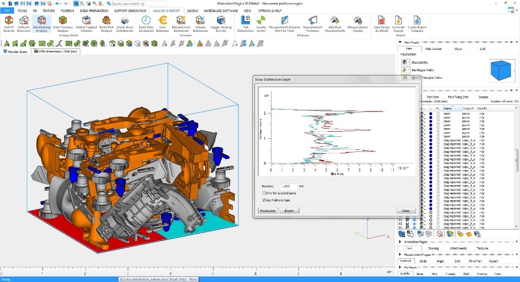
Printing a myriad of parts, each with its own serial number, that have been combined or batched into the same build plate/platform (see Figure 1 below) raises the additional challenge of guaranteeing that unique serial numbers were generated for each part, then 3D-printed on each Part, and subsequently tracked by each individual serial number.
Figure 1 Multiple parts on the same build plate (courtesy of Materialise)
Similar to tracking parts through the various operating steps that comprise your various heat treat processes, AM facilities also must have real-time visibility into each step of the part-production process, tracking where each part is in the overall process (i.e., which operating step each part is on, all while integrating the necessary quality management into the mix.
When AM production facilities send many different kinds of parts (all with unique serial numbers) to heat treat facilities with some parts requiring different processing steps, the software systems need to be able to track in real-time exactly where each individual part is located within the facility. Even though the heat treater is not responsible for generating and assigning serial numbers to the parts, there still needs to be complete traceability, accountability, and auditability of every step of processing that was associated with that part, especially if it was determined that there was a part failure in the aerospace, aviation, or medical end-use application of that particular part.
Serial numbers on parts can be generated from multiple user-defined serial number formats or templates, along with the ability to specify certain characters that should be excluded from automatically generated serial numbers (such as “o”, “l”, “I”, “x”). Each company, division, or AM production facility may have a different format it wants to use, such as a combination of plant #, date, time, and printer #. Regardless of the format used, serial numbers must be unique. Additionally, the template used must be able to be individually assignable for every customer part (and the same part # might be used by multiple customers).
There are multiple ways that serial numbers can be applied to the parts before they are sent for heat treating. Both AM facilities’ and heat treaters’ production floor software must provide for detailed serial number tracking of all parts throughout the build and post processing activities, from the beginning of AM production (after the part design phase) all the way through to heat treating, finishing, testing, and shipping.
Sometimes AM parts that heat treaters receive will also have a build plate ID as an additional identifier, along with the serial number. Build plate IDs are typically platform-centric, with the appropriate process management/operating steps applied for the various parts that are to be produced on that platform or build plate. The build ID needs to connect all of the related work orders for traceability as well as electronically linking all documentation/forms associated with a particular work order and build ID. The documentation audit trail of individual processing activities needs to be kept intact when the parts are sent to an outside heat treat vendor as another one of the required operating steps for that part. In addition to this, the actual build plate can either be tracked as a separate piece of equipment (typical) or as an inventory item.
For heat treating as well as AM production facilities, an integrated equipment maintenance module needs to be tied directly to production control (on the selected piece of equipment) and part specification requirements, to ensure the build plate, 3D printers, furnaces, testing equipment, etc., are serviced, calibrated, and/or maintained appropriately for compliance and optimal use.
Along with having a work order just for the build plate, there can also potentially be one work order for each part on the build plate, and that work order can be used to generate a vendor traveler to accompany the parts to the offsite heat-treating facility. Figure 2 below gives an example of two different part-build work orders on the same build plate.
The build work order tracks the actual build process, similar to tracking every step of the heat treat process, and provides operator instructions that may include pictures, diagrams, videos, or specification requirements. Then when the various parts/coupons/test bars are removed from the build plate, they travel either within your facility or to outside vendor post-processing and are tracked on their individual work orders.
Two specific tracking/configuration possibilities need to be managed by the MES/QMS software:
All parts on the build plate following the same process/route (i.e., operation steps)
Parts/coupons/test bars that take separate processing routes from the build plate—some may be sent on to heat treating, and others may be sent to destructive testing
Very similar to heat treat processing, AM production facilities need to have the ability to define and generate new work order packages to rapidly repeat previous work order part builds with exactly the same part-build process, but also have the capability to use the latest version of processing requirements and specifications for the selected part(s). This supports the global goal for repeatability, higher quality, and fewer nonconformances in AM part production with complete, auditable historical production data that maximizes throughput and, I might add, to run as paperless as possible (Internal and external auditors hate digging through file cabinets.). Most heat treaters have done a great job of mastering the art of part process repeatability for the repeat parts their customers continue to send to them.
Even though there is a continuing goal to keep reducing the number of nonconformances in part builds, nonconformances, especially in start-up AM production facilities, do occur frequently and must be managed accordingly on the production floor. Similar to the requirements of post-processing facilities, including heat treating, shop floor software systems need to be able to show supervisors and senior management what is really happening on the production floor in real-time with greater visibility and to continuously keep track of each individual part with the appropriate documentation to back up the decisions that were made on the fly on the floor, whether it is
Nonconformance dispositioning
Customer concession granted
Applied CAPAs (corrective and preventive actions)
Quality characteristics (or data questions that must be answered by the operator)
Control plans
Part sampling plans
Customer PPAPs (production part approval process)
Additional requirements may include:
Document management with version control
Compliance and specification management and assurance of adherence
Interfacing with individual pieces of equipment (including part testing equipment)
User viewing restrictions (i.e., ITAR, EAR, etc.)
Integration with ERP systems (including the customer’s ERP system)
Real-time notifications of certain triggering events (via SMS and/or email)
Equipment maintenance per specification requirements tied directly to production processing control
Ability to use mobile devices to access the system anywhere, anytime, any device
Raw material usage tracking (with automatic reorder notifications per preset thresholds)
Visibility into what is really happening on the production floor in real-time
Ability to conduct a risk assessment (per ISO 9001:2015)
SPC (statistical process control) to spot negative trends before out-of-tolerance conditions occur
Manage the order hold process related to scrap parts, nonconformances, etc.
Facilitate outside processing (i.e., heat treat, coating, finishing, testing) via a vendor traveler
Manage real-time changes to part specifications and the sequence of processing steps
Ability to attach various media to individual operating steps in the part-build process
Automatic qualification of equipment, personnel, and vendors used in the AM part-build
Real-time splitting and combining of parts in the various operation steps within the work order to optimize the routing and scheduling of work on the production floor.
Each of these system requirements has its own set of unique functions that support processing an individual part, whether it is heat treating, surface finishing, coating or additive manufacturing, but there are some overlap and similarities of the part servicing requirements. There is also a big corporate continuous improvement quest, regardless of the type off services a company provides. A lot more can be said about the specific use of each of the bulleted items above, but since I wanted to keep this article somewhat short and to the point, those can be covered in a future article, or you can reach out to me at ron.beltz@go-throughput.com with any questions or need for clarification on any of the items. Happy heat treating of more AM parts!
Ron Beltz serves as Bluestreak I Bright AM’s™ Director of Strategic Accounts and assists in marketing strategy while managing the sales and business development activities from the company’s Tampa, Florida, location. Ron is a graduate of Control Data Institute of Technology and also received additional training from Hewlett Packard, Digital Equipment Corp., and the Dale Carnegie Management Training Series. Prior to joining Bluestreak™, Ron has functioned as director of IT/CIO for a steel company in Canton, Ohio, and technical director for a multinational consulting firm, serving as an engagement manager over teams in the U.S., Canada, India, and a nearshore solution center located in Montreal.
Ron has assisted many organizations with determining their specific requirements and packaging turnkey solutions which achieve the business/operational goals set forth. He has served on several boards, been invited to present at IT users groups, technical schools, class graduations, and was a previously elected official.
A global aluminum manufacturer of products for multiple applications, including aerospace, automotive and packaging, recently announced that its Ravenwood, West Virginia, facility has been selected by the U.S. Department of Defense for a nearly $9.5 million grant to increase throughput, quality, and performance of cold-rolled aluminum.
Constellium will perform electrical, mechanical, and hydraulic system upgrades to Ravenswood’s 144" cold rolling mill, which is critically important for the manufacture of high-performance aluminum plate for ballistic and blast protection of military vehicles.
The funding was awarded to Constellium SE by the U.S. Department of Defense’s Cornerstone OTA and will be managed by the Army Research Laboratory (ARL) at Aberdeen Proving Ground, Maryland. Constellium will use the funds to perform electrical, mechanical, and hydraulic system upgrades to Ravenswood’s 144" cold rolling mill and add state of the art automation and process controls. The mill is critically important for the manufacture of high-performance aluminum plate for ballistic and blast protection of military vehicles. Army and Marine Corps modernization programs will require an increased capacity of the U.S. industrial base to produce cold rolled plate over the next decade. In coordination with Cornerstone and ARL, Constellium will also invest in developing manufacturing processes and armor plate that will optimize the additional capacity and process controls of the upgraded mill.
Buddy Stemple, CEO of Constellium Rolled Products Ravenswood
"This investment by the Department of Defense will enable us to meet the increased demand for cold-rolled plate over the next 5 to 10 years and also significantly improve the performance of armor against constantly evolving threats," commented Buddy Stemple, CEO of Constellium Rolled Products Ravenswood. "We are very excited to have this opportunity to help protect our troops."
Heat TreatTodayoffers News Chatter, a feature highlighting representative moves, transactions, and kudos from around the industry.
Personnel & Company Chatter
A leading provider of metal and carbon fiber 3D printers, Markforged, recently announced the opening of a new manufacturing facility in Billerica, Massachusetts. The 25,000 square-foot space will enable the company to more than double its production capacity, support increased demand for Markforged 3D printers, and create new jobs.
Rodrigo Belloc has been appointed the president of Gerdau Special Steel North America, Jackson, Mich. He replaces Mark Marcucci, who is retiring from his position after 28 years with the company and 43 in the steel industry. Previously, Belloc was CEO of Gerdau Diaco in Colombia and Gerdau Metaldom in the Dominican Republic.
Allied Mineral Products opened the doors to its newest precast shapes manufacturing facility near Johannesburg, South Africa. This marks Allied’s sixth precast shapes location worldwide.
Vorteq Coil Finishers LLC, a provider of coil coating services for metal products, recently acquired the assets of California-based Western Metal Decorating, which produces coated aluminum and steel products serving pre-painted markets. As part of the transaction, the Western operation will be renamed Vorteq Pacific LLC.
Leica Microsystems is delighted to announce a new UK partnership with Struers Ltd., the UK’s leading manufacturer of equipment, consumables, and services for materialographic analysis. Leica microscopes, accessories, and imaging products specifically designed for industrial and material analysis applications will now also be available from Struers Ltd. in the UK.
Getec Industries added friction stir welding (FSW) services to its Thermal Solutions division in Torrance, California. The new capabilities will enable the company to supply large extruded aluminum heat sinks to the electronics industries.
Equipment Chatter
Inductotherm Heating & Welding recently announced the successful commissioning of a new Thermatool 250kW CFI welder to GRC LLC.
Kudos Chatter
MTI recently recognized three Solar employees for their commitment to MTI. On October 5, Bob Hill, President of Solar Atmospheres of Western PA, was honored with the prestigious M. Lance Miller Legend Award, in recognition of his leadership and lifetime commitment to the heat treating industry and MTI. Hill’s heat treating career began in 1980 when he joined Precision Heat Treating, Inc. as Vice President. Hill moved on to Solar Atmospheres of Souderton PA in 1995. Within five years, Hill was promoted to President, to head Solar’s newest venture 370 miles away in Western PA. In addition to Hill’s involvement with MTI, two other employees from the Solar Family of Companies—Patrick Reilly and John Hahn—are recent graduates from YES, MTI’s Leadership Training Program
Innovation Leader awards recently went to SECO/WARWICK for the third time. The “Business Leader” event is a prestigious competition. The jury gives awards to the companies distinguished by their transparency and business honesty with innovative successes as their trademarks. On October 28, 2019, at the prestigious gala, Katarzyna Sawka, Global Group Marketing Director SECO/WARWICK, received the Innovation Leader Award on behalf of the company.
Bodycote recently celebrated Dan McCurdy, who retired in June 2019 after 21 years of service, as this year’s recipient of the prestigious HTS George H. Bodeen Heat Treating Achievement Award. Dan received the award at a ceremony during this year’s AMS International Heat Treat Conference event that was held in Detroit on October 15-17, 2019.
Katarzyna Sawka, Global Group Marketing Director SECO/WARWICK, received the Innovation Leader Award on behalf of the company.
Heat TreatToday is pleased to join in the announcements of growth and achievement throughout the industry by highlighting them here on our News Chatter page. Please send any information you feel may be of interest to manufacturers with in-house heat treat departments especially in the aerospace, automotive, medical, and energy sectors to Karen Gantzer at karen@heattreattoday.com
Jack Titus (Photo courtesy of Dagenais Photography)
Jack Titus has managed a R&D metallurgical laboratory with all manner of scientific instrumentation as well as transferred plasma nitriding, LPC and HPGQ (high pressure gas quench) technology from around the world to the U.S. He holds patents on vacuum furnace and vacuum carburizing technology.
In this article for Heat TreatToday, Jack shares his experience as a member of a team whose task was to transfer the nitriding process known as ion nitriding. The lessons he learned are valuable to heat treaters today.
Photo: autosport.com
One of the ways companies advance their technology offering is by transferring technology from other sources, primarily offshore entities that have developed a process that has been successful in their home market. However, there are associated risks because what has been accepted in one market may not be as popular in another. One major variable is the different design culture: an intangible that is easy to overlook. An analogy I often use when explaining this cultural difference deals with race cars. European Formulae One race cars have a sleek-looking, open-wheel design that’s easy on the eye. In contrast, the NASCAR grand-national series of race cars appears bulky and rugged—more like our passenger cars—and look crude compared to Formulae One, but they have huge engines and are fully capable of reaching speeds of well over 200 mph.
European—especially German—engineered furnaces often appear as sleek looking as Formulae One cars and are very capable of successful heat treating, but they are fragile and require more attention to maintenance than their U.S.-based counterparts. This was certainly the case with Degussa and their 20-bar vacuum furnaces and sinter–hip systems, as well as ALD’s low-pressure carburizing (LPC) and high pressure gas quench (HPGQ) systems. The following discussion documents my experience as part of the team that endeavored to transfer the nitriding process known as ion nitriding, developed by Kloeckner Ionon GmbH, a German company that advanced the process in the mid-1970s. The process and events are accurate as far as my memory from that era can muster. I’ll use initials for the names of the companies or the individuals and substitute “The Company” for the U.S. transferee.
The transferee team consisted of a manager, a marketing director, and others tasked with “Americanizing” the product—a big mistake. My task was to spend about a month at a Kloeckner commercial heat treat facility learning how the process was controlled and the do’s and don’ts for preparing loads so I could train potential users on the technology. To further the effort, company S purchased a smaller production unit from Kloeckner with all of the current state-of-the-art (German) controls to be installed in the R&D section of The Company for conducting sales tests.
At that time in the mid-1970s, other U.S.-based companies were just putting their toes in the water to see if the process was real, but Kloeckner was the perceived expert in the field.
The unit placed in R&D was a fully capable vertical unit with a hearth plate 24-in. (609 mm) diameter by 48 in. (1219 mm) high, the result of years of development by Kloeckner. The Company was just entering the digital age, upgrading from analog controls, so the decision was made to develop their own process control for discrete logic and temperature control. All of the voltage, ampere, and temperature controls in the Kloeckner unit were analog with dampening features that made for very smooth outputs. Again, at the time, Allen-Bradley was the primary manufacturer of PLCs used by company S for furnace motion control, but the nitriding unit had no material handling requirements, therefore, all of the controls were process variables, making a full blown PLC unnecessary. Barber Coleman was the other digital controller company that specialized in plastic injection molding process control using their EDAC programmable logic controller, which made it the logical choice for the primary controller. It employed EPROMS that could be programmed and erased at will, making logic changes much easier. The EDAC was also used on The Company’s vacuum furnaces successfully, so using it seemed a wise course.
For those unfamiliar with plasma nitriding, the following is the Reader’s Digest version of the process:
A DC voltage converted from AC via a series of diodes with a maximum of 1000 volts is applied to a work piece and is the cathode of the circuit. Radiation shields and the vessel proper are the anode with a positive ground. When the power is applied to the parts and nitrogen and dissociated ammonia are used, it produces a purple glow. The learning curve associated with plasma nitriding is pretty complex, and dealing with holes—especially blind holes—can be problematic.
When power is first applied to the work piece after evacuation the moisture and/or residue left on parts causes a long delay in heating as an arcing phenomenon begins. Specialized circuitry in the logic measures the voltage drop as arcs occur and “crowbars” the power to a choke, a transformer that absorbs the current and allows it to dissipate to ground. In doing so, a huge magnetic field is created that must be accounted for, and that is one of the reasons the EDAC was used. It was intrinsically hardened against such severe interferences so much that, with the choke side of the cabinet door opened, the image on the EDAC CRT was pulled off the screen momentarily without any damage to the processor.
The glow produced by the energy is referred to as the glow seam: as the partial pressure in the vessel increases, the glow seam becomes thinner and power is concentrated. It could then create a seam overlap resulting in very intense and localized power within holes of a certain size, enough to locally melt the metal. When processing parts of various sizes and shapes, care must be taken to avoid these circumstances.
One of the disadvantages of the process is the very long time it takes for the sparking and arcing to subside and allow enough continuous power to heat the parts. Pre-process degreasing and/or thorough washing was mandatory to reduce the sparking and arcing time. We eventually learned that preheating parts, even in air, to 400°F (204°C) dramatically improved heating time. Part of Kloeckner’s control logic embedded within the solid-state circuitry counted the arcs per second. If the arcing reached a certain level, power was reduced, which allowed a more sustained applied energy—improving the heating time but not nearly the same positive effect as preheating.
During my initial visit to a Kloekner heat treat, I was astounded at the amount of hands-on experience required to control the process. Since nitriding takes place between 900°F (482°C) and 1000°F (537°C)—which is below the visible color range—when viewing through a sight glass, the operator would cover himself and the sight glass with a black photographer’s cape so as to shield out ambient light, allowing him to easily see the dull red of the relative temperature of the parts in the load. Along the way of transferring the process learning curve, it became obvious why Kloeckner only employed pit vessels for plasma nitriding. Since there was no additional heat source other than the energy produced by the glow seam, parts located in the center of the part array would heat much faster than parts positioned around the perimeter of the circular base plate. Therefore, when processing multipart loads, parts expected to take longer to heat would always be placed in the center of the arrangement.
As a typical load was coming up to heat, the operator would visually inspect the parts for color variation and, if detected, pause heating until all parts became uniform before continuing to heat. A thermocouple was used for temperature control; however, placing it required some experience. The end of the TC was protected by an alumina tube to isolate the high voltage and prevent it from shorting to the TC and damaging the analog to digital input board.
I recall that in the mid-1970s, furnace OEMs were just beginning to find ways to relieve the operator from having to make process decisions by incorporating more intelligence into controllers, yet here was a process that required more human intervention not less.
One of the major mistakes The Company made during the learning curve transfer was selling the Kloeckner sales unit to a commercial heat treat in Fort Worth that already had a U.S.-developed (but larger) nitrider. I strongly opposed this move because it would compare Kloeckner’s mature product with years of development behind it and its fluid operation to our new larger unit where development was in its infancy. The Company’s nitrider design reflected the same engineering as their pusher furnaces—over-designed, bulky, and lacking the mature engineering that flows from an evolved design. As a result, the news spread that The Company’s product was not equal to the German unit. Compounding that error in judgment, our marketing director, affectionately known as “Wild Bill”, was promoting plasma nitriding as the end all process before we knew all of the process’s benefits and shortcomings.
Traditional nitriding is still an atmosphere process where little care is required in making up part loads, while plasma nitriding requires careful planning to avoid overlapping the glow seam when parts are placed on the base plate or positioned on racks. As word spread throughout the industry about the special attention and loading complexities required, the honeymoon was short-lived.
A classic example of loading issues arose when I was asked to assist in creating a loading arrangement for synchronizer rings for Chevy Muncie, where the first horizontal vessel was sold. It consisted of two vessels sharing one vacuum system; however, each had its own power supply. Those involved had designed a flat horizontal base plate with vertical posts where rings were placed with spacers between each to avoid the expected overlapping glow seam. The main problem was nonuniform heating from the center to the perimeter, since all parts were the same mass and size. The solution was to orient the load horizontally to align it with the horizontal radiation shields. The rack supporting the rings was circular with an open center. The main support allowed for horizontal posts projecting out on opposite sides of the center support so rings could be slid over the posts while retaining the spacers.
I recall a funny story early in the development when a small laboratory-size ionitrider was designed for experimentation and was sold to two gentlemen who planned on building a commercial enterprise for nitriding. In a rented garage in Iowa with a garden hose supplying cooling water in the evening after normal working hours, I was instructing the two guys and their wives on the operation using the EDAC. Three of the four looking over my shoulder were completely perplexed as I was populating the screen with temperature inputs, pressure, and so on. Suddenly one of the wives blurted out, “Hey! There’s nothing to this! It’s just like my microwave.” And from that beginning we have the rest of the story: Advanced Heat Treat in Waterloo, Iowa.
The moral of this story is this: When transferring technology, change as little as possible, because if do, you are doomed to repeat the evolutionary mistakes that the original design team experienced.
If you attended the 2019 Heat Treat Conference and Exposition in Detroit a few weeks ago, you received special tape from Heat TreatTodayto repack those important items. Take a look at how some folks put the HTT tape to use. If you’ve got interesting and creative ways that you’ve made the HTT tape work for you, please share your photos with us at editor@heattreattoday.com.
A new heat treat system that will help produce products for the logging industry has been ordered by Oregon Products.
Oregon Products, a brand of Blount International, Inc., will be adding a new continuous high capacity mesh belt austemper heat treatment system to its production facilities. A global manufacturer of saw chain and other replacement products for the forestry industry, Oregon plans to use the new equipment as part of a long-standing commitment to continuous quality improvement.
Kaitlyn McNaughton Director of Engineering and R&D Labs Blount International
“The primary business driver of this project is quality,” said Kaitlyn McNaughton, Director of Engineering and R&D Labs. “This new furnace is primarily targeted to raise the bar on quality for our harvester chain products, which perform under the highest loads and most extreme conditions.”
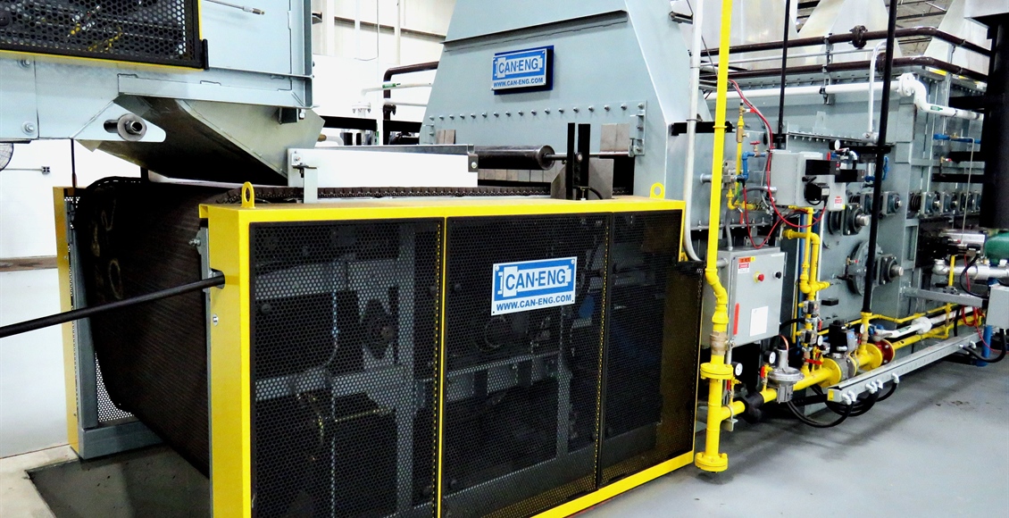
The austemper system, which CAN-ENG Furnaces International, Ltd. will design and commission, integrates a computerized loading system, pre-wash system, atmosphere-controlled mesh belt austenitizing furnace, molten salt quench conveyor system, post quench residual salt removal and recycling system, mesh belt parts drying oven, unloading system and CAN-ENG’s PET™ system which provides vital features such as individual lot/product traceability, detailed process data collection for continuous process improvements and comprehensive Industry 4.0 equipment diagnostics capability.
The system is scheduled for commissioning early 2020.