Heat treaters often target gas nitriding and carburizing as key additions to their facility, but sometimes they miss a low-cost opportunity for big wear improvement called Deep Cryogenic Treatment. What is it and could it be a game changer for your business?
This Technical Tuesday feature was written by Jack Cahn, president of Deep Cryogenics International and was first published in Heat TreatToday's May 2022 Induction Heating print edition.
Jack Cahn President Deep Cryogenics International Source: Deep Cryogenics International
Benefits
Deep Cryogenic Treatment (DCT) is a thermal process which provides 20–70% increased wear life, 10–20% increased ultimate tensile strength (UTS )/yield strength, and up to a 30% reduction in corrosion effect (Figures 1 & 2). Unlike case hardening or surface coating there is no part distortion, and cryogenically treated items are not prone to fatigue cracking. Whereas nitriding leaves a recast or white layer, DCT does not. Unlike all three processes, dissimilar materials (such as ferrous and non-ferrous) with varying geometric thicknesses can be treated together to increase mechanical and chemical properties. DCT can also be combined with gas nitriding to yield fine precipitates of carbo-nitrides and thru-core eta carbides — combining the best of diffusion and quenching with a diffusion-less thermo-kinetic process (Figure 3). DCT offers permanent, non-reversible wear improvement with no degradation over time.
(Left) Figure 1. Yield strength improvement; (Right) Figure 2. Corrosion reduction Source: Deep Cryogenics International
Many knife and tool steel manufacturers recommend the use of DCT after austenitizing and quenching but before tempering. It is standard industry practice to employ DCT to increase the wear life of D2, H13, S7, 440C, and several mold steels used in the plastic injection, stamping, and forging die industries.
DCT is also one of the lowest cost thermal processes available to heat treaters who already support exothermic and endothermic processes using onsite liquid nitrogen. Environmentally, DCT is neutral: it improves metallic wear life but leaves behind no chemicals, waste, or cleanup and requires no flammable, hazardous, or explosive gases. Fifteen of the 20 largest commercial heat treaters in North America promote their own DCT services and hundreds more have small DCT equipment.
Figure 3. Wear resistant carbides Source: Deep Cryogenics International
How It Works
The DCT process usually follows austenitizing and quenching and is, effectively, a continuation of the quench process below martensite start and finish temperature. Items are placed in a specially designed chamber and slowly cooled from ambient to approximately -320°F (-195.5°C) over six to eight hours and then maintained in a dry, nitrogen gas environment for 8–30 hours before slowly returning to ambient — followed by 1–3 tempering steps. Round, vacuum-insulated processors use less liquid nitrogen (LN2 ) than rectangular chambers and can temper heavy items in-situ (Figure 4).
Figures 5a. MnS inclusions in G2 cast iron; baseline Source: Deep Cryogenics International
Figures 5b. MnS inclusions in G2 cast iron; DCT Source: Deep Cryogenics International
Figure 6. 14,000 lbs of Mn crusher cone mantles in the 36K Source: Deep Cryogenics International
DCT is a diffusion-less thermal process that causes the transformation of retained austenite into martensite without embrittlement and the precipitation of primary and secondary eta carbides. With a low enough temperature and soak time there is a phase change from face-centered cubic (FCC) into body-centered cubic (BCC) or hexagonal close packed (HCP) slip systems. DCT relieves both cyclic and imposed stresses in metals caused by heat treating or manufacturing, further reducing the migration of crystalline defects such as stacking faults, dislocations, inclusions, and vacancies (Figures 5a & 5b). With the reduction in defect migration comes a reduction in interatomic spacing — directly lowering fatigue crack nucleation and propagation.
The process is effective on castings, forgings, additive manufactured, and fully machined items because DCT is a through-material process — maintaining wear protection long after surface coatings and case hardening have eroded. With the recent availability of industrial DCT equipment capable of treating parts 8’ x 8’ x 20’ and up to 30,000 lbs., the process now can be used on large turbine, oil and gas, and mining components previously cast too large for DCT (Figure 6).
So, with all these benefits, why has this process been so overlooked and underused?
Early Adoption and Stall
In the 1980s, heat treaters accepted cold treatment (-80°F) to reduce retained austenite and, later, shallow cryogenic treatment (-140°F to -240°F) to reduce residual stress. However, a lack of DCT test labs that could scientifically demonstrate DCT wear benefits, no large capacity DCT equipment available, and no DCT-specific ASTM test methods were key barriers hampering market growth. Unfortunately, DCT doesn’t show increased wear improvement using the universally adopted Rockwell hardness test ASTM E18-20. Without a specific ASTM test to validate process improvement and no suppliers of large size DCT chambers to complement the existing car bottom industrial furnaces, few heat treaters readily adopted DCT. The DCT chamber frequently sat unused in a corner of the shop.
The Current Opportunity
The key breakthrough for the DCT technology has been the evolution of industrial size equipment. Built and prototyped by Deep Cryogenics International in late 2021, the 36K offers heat treaters a new means to expand their service offerings and new capacity to DCT large parts. Since the 36K cryogenically treats at -320°F but also tempers to 350°F, the entire process (including post-DCT tempering) can be performed in one chamber. No longer will capacity be a technology limiter.
A new business model has also changed the DCT industry: low-cost leasing. By removing the high cost of capital purchase, Deep Cryogenics International’s captive leasing program offers heat treaters access to industrial scale DCT, coupled to an on-site liquid nitrogen generator and a 3,000-gallon storage dewar. Now LN2 can be generated on site at less than bulk supplied gas — dropping the “all in” cost of DCT to less than $0.20 per pound.
Figure 7. DCI VP Linda Williams next to the 36K Source: Deep Cryogenics International
Lloyd’s Register is currently qualifying both the 36K and the DCT technology using a new approach to a recognized test standard — ASTM E2860 Residual Stress testing using X-ray diffraction. This non-destructive test method will positively identify DC-treated parts and correlate a level of improvement based on the drop in residual stress.
2022 will be a big year for DCT with a lot of firsts: large capacity equipment, a captive leasing program, and industry test and certification.
About the Author: Jack Cahn is president of Deep Cryogenics International — a manufacturer of DCT equipment with an in house DCT research lab. His 25-year background in DCT includes design and development of DCT procedures used in scientific, military, energy, and mining applications. He is the author of several patents, certification marks, and research papers. DCI will be opening a DCT demonstration facility in southern Alberta in June 2022.
Heat TreatRadiohost, Doug Glenn, talks with Greg Steiger of Idemitsu Lubricants America Corp. about the causes and dangers of water in your quench tank, how to know if you have too much, and what to do about it if you do. This highly-informative episode is a must watch/listen for those who oil quench.
Below, you can watch the video, listen to the podcast by clicking on the audio play button, or read an edited transcript.
The following transcript has been edited for your reading enjoyment.
Doug Glenn (DG): Greg, welcome to Heat TreatRadio. This is the first time you’ve been on, and I know we’ve talked about doing this for quite a while, so, welcome!
Greg Steiger (GS): Thank you, it’s my pleasure.
DG: I asked the question, before we hit the record button, but I think we need to ask the question again: The big white flag in the background with the W, you need to tell us about that.
GS: That’s the flag that they fly outside of Wrigley Field every time the Cubs win. They’ve been doing this for almost a century so that way when they were only playing day baseball and you could come home on the L, you could see if the Cubs won or lost without looking at a box score.
DG: That’s great! Now, you are not in the Chicago area, are you?
GS: No, I’m in the Columbia, SC area, but I was born and raised in the Chicago area.
DG: So, you’re a Cubby fan.
GS: I am.
DG: Being from Pittsburgh, I forgive you for that.
So, Greg, first thing, can you give our listeners and viewers a brief background about yourself and then we’ll jump into the water topic, so to speak?
GS: Sure. I got into this industry when I graduated from college in 1984 as a formulating chemist. I eventually worked my way into, what we call, customer service or tech service, where I’d go out and visit customers, run product trials if customers had problems. I worked my way into laboratory management and eventually sales and marketing. I’ve been at Idemitsu for the past 9 years. Since I’ve been at Idemitsu, I’ve earned a master’s degree in materials engineering, and I’ve learned a lot about heat treat and it’s really become my passion. I am currently the market segment leader for heat treat products for Idemitsu.
DG: I should congratulate you on that degree, by the way. I know a year or so ago, you were still working on that, so that’s great!
GS: May 6th I graduate.
DG: Tell us, just briefly, for those who might not know about Idemitsu. We can see it on your shirt but tell us about them a little bit, so people have a sense.
GS: Idemitsu is a very well-kept secret here in the U.S. They are actually the 8th largest oil company in the world. We are a Japanese owned company. There is about an 85-90% chance that no matter what vehicle you drive, you’ve got some of our fluids in it. The largest market share is the automotive air conditioning compressor market, but basically, if you drive a Honda, Mazda, Subaru, or Toyota, it left the plant with our engine oils, our transmission fluids in it at the factory.
When it comes to quench oils on the industrial side, Idemitsu is actually the 2nd largest quench oil provider in the world. Even though we’re Japanese, all of our heat products, in general, are made and blended here in the U.S.; we don’t import anything from Japan for our heat treat products.
DG: Very interesting. So, a big company — somebody worth paying attention to, I think is the point. You’re right — it’s the best kept secret. We’re trying to work to not make it so secret.
GS: We’re doing what we can, Doug.
DG: This next question I’m going to ask you is very, very basic and most people listening I’m sure will know this but there may be some who don’t: Why is water in quench oil a problem?
GS: A little bit of water is not a problem because it will happen naturally through condensation, but when you start to get too much water in there, a couple of things happen. Our research has shown that basically about 200-250 ppm water, you start to get uneven cooling.
A quench oil is not a completely homogenous fluid; it’s possible to have water in one area of the tank and no water in the other so you can get different cooling speeds in different areas of the tank. When you start getting up to large amounts of water, somewhere around 750 ppm to over 1000 ppm, it becomes a safety issue. What happens is — when water turns into steam, it actually expands. Most things when they get warmer, they contract, but water is the opposite — it expands. It expands 1600 times at boiling and the hotter the steam gets, the more it expands.
"A little bit of water is not a problem because it will happen naturally through condensation, but when you start to get too much water in there, a couple of things happen. Our research has shown that basically about 200-250 ppm water, you start to get uneven cooling."
Think of it: If you have a gallon of water in a 3,000-gallon quench tank, when you boil that water, it turns into 1600 gallons of steam, and it’s got nowhere to go but up and out of the quench oil and it’s going to carry the quench oil with it onto flame curtains, other hotspots on the furnace, and that’s why it becomes so dangerous.
DG: It’s really the risk of explosion, in a sense. That’s basically what we’re talking about. I could be wrong, but my gut feeling is that a vast majority of quench fires are started because of water that happened or simply the product not getting down into the quench fast enough. But a lot of it is caused by carrying water in with the part.
GS: Not necessarily on the part but being in the oil itself through various means. As I said, it happens naturally every time you heat an oil up and you cool it down, you get condensation, but that’s usually only a few parts per million, and every time you drop a load in, you’re driving that water off.
DG: Right. Raising up the temperature and therefore boiling off the water.
GS: Right.
DG: This is a follow-up question into what we were just talking about, and maybe we’ve answered it: Where does the water come from? Is it typically just condensation or what are the top ways water gets into the tank?
GS: Condensation is something we can’t prevent because we live in a hot, humid environment. But what we can prevent is human error, and that’s where most of the water comes from. For instance, if a heat treater has their quench oil stored outside, perhaps in totes — it’s particularly important to make sure that the caps and lids on these totes or drums are very tight and secure because otherwise they’ll get condensation in there and rainwater in there.
We’ve seen instances where people are working on a furnace, and they will hit the sprinkles and the sprinklers will set off and put water into the quench oil. Heat treat furnace doors and, not so much anymore but, heat exchanges where water cooled. Anything that is under pressure is eventually going to leak and that’s why you see companies going to air-cooled heat exchangers. It’s still more difficult to get that air-cooled door and there is still some water in those doors. Like I say, anything under pressure is eventually going to leak and that’s where you see some of the water infiltration, as well.
DG: Typically speaking, how warm or how cool is the oil in a quench tank? You mentioned about condensation being caused by when it cools down, you’re going to have some condensation in there. Where do we run those tanks?
GS: It depends on if you’re using a hot oil or a cold oil. A cold oil is basically an oil that you add some heat to get it around 130-160 F, then you use your heat exchangers to keep taking the heat away when you quench the load in there. A hot oil you add heat to constantly because you want to keep that typically 250-300 F. In a hot oil, you really don’t have a lot of issues with water, unless the furnace goes down and then you get a lot more condensation than anything else. Now, cold oil, you have issues with water because you’re not above the evaporation point of the water.
DG: The bottom line is: If you’ve got too much water in the quench tank, it’s an issue.
Tell us about the measurement. How do we know if we’ve got water in there, and how do we know how much we have?
GS: Well, there are some portable test kits out there. The ones I’m familiar with are made by the Hach Company. You can purchase these from industrial supply houses like McMaster-Carr or places like that. They will give you ppm’s of water.
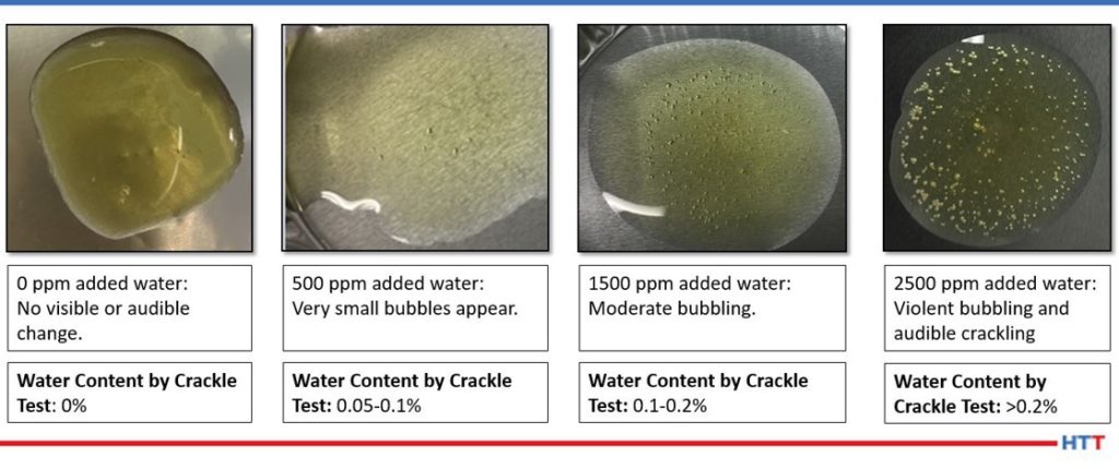
You heard a lot of old-timers always talk about crackle tests. That is not an effective way to determine how much water is in there. Our studies have shown that you can get as much as 1000-1500 ppm of water before that oil starts to crackle. The way you run a crackle test is — you take a hot panel, (that’s hotter than the boiling point of water), put a couple of drops of oil on it and if it crackles, there is water in there. Sometimes, the oil is so thick, it doesn’t really crackle, and you can’t see it until you get too much water in there.
The way all quench oil providers do it in their lab is something called a Karl Fischer titration. This is not something that the typical heat treater would have in their lab — it’s a relatively expensive piece of equipment. We use automated ones because we do so many at a time, but you can buy manual ones, if you’d like, and those are a little bit less expensive, but again, you’re talking about laboratory equipment and you’re talking about thousands of dollars instead of hundreds of dollars.
Another way to determine if you have water in your quench oil, especially on lighter colored quench oils, is to take a flashlight, put it in a clear beaker, and take a flashlight and put that flashlight at the bottom of the beaker. If nothing in that beaker is hazy and everything is very clear and amber and you can see through it, chances are there is no water in it. But if it’s a dark quench oil, like a lot of cold oils are where it’s almost jet black, the flashlight won’t do you any good.
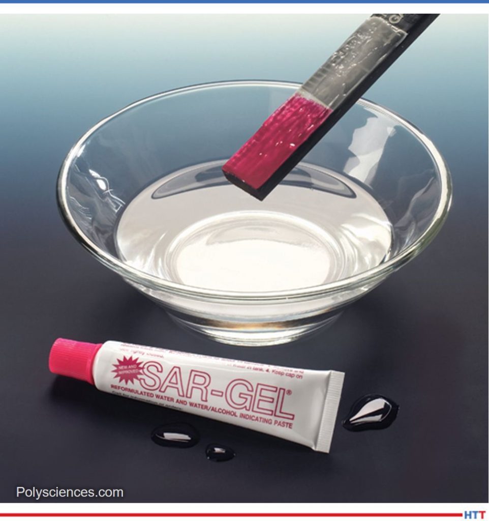
One of our customers has talked about using a paste. Unfortunately, I don’t know the manufacturer of it, but what he did is he took a paste and put it on a wooden stick and stirred it all throughout its tank. The paste didn’t turn colors, so he knew there was no water in it. To prove that the paste was still good, he actually licked a finger and put it onto the paste and the past turned pink.
DG: This paste that you put on the stick, it doesn’t dissolve into the liquid — it’s just testing whether there is water there. And if it changes color, then you’ve got water. We’ll have to find out what that is and maybe we can put a note about that on the screen.
DG: Probably the best, most reasonable method that doesn’t cost so much, is maybe getting one of those testing kits. Do you have suggestions, Greg, on how frequently a heat treater ought to be checking his or her tank for water?
GS: I would say weekly. I don’t think it needs to be tested any more unless you think there’s a problem. If there’s a problem, obviously, test as often as you need to. But weekly is good enough.
Again, when you’re dropping a load into quench oil, you’re anywhere from 1300-1800 F, so when you drop that load in, you’re driving almost all of the water off that would be in the quench oil from condensation. It’s just if you’re worried about some sort of a human error, that’s when you want to take more frequent testing.
DG: So, it’s going to be somewhat dependent on your process.
How about the material that you are quenching? Are some materials more sensitive to water than others, or is not really an issue?
GS: Not really. It’s more of an issue of part geometry. And that goes really for distortion and cracking along with the water. A little bit of water can crack a very thin part, but on a very thick part, it may not have much effect at all.
DG: How about cosmetics? I know that some people are very concerned with cosmetics. Is water in the quench oil going to cause any issue with cosmetics, such as spotting?
GS: Short-term no, long-term yes. What causes a lot of stains is oxidation. Water, when it heats up, will actually dissociate into hydrogen and oxygen. The hydrogen won’t oxidize the oil, but the oxygen does. That’s one of the reasons why heat treaters use flame curtains — not to allow the oxygen from the atmosphere into the furnace. At the temperatures that you heat treat at, it doesn’t take much oxygen presence to oxidize not only the parts, but also the oil.
DG: We talked briefly about why water is a problem. We talked about measuring it and trying to determine if you have an issue. Let’s move on to this: Ok, we’ve got water in the quench and it’s at an unacceptable level. What do we do?
GS: There are a few ways to do it. It really depends on what level of water you’re at, how safe you feel, and how soon do you need that furnace. Many furnaces have a bottom drain. If you turn the agitation off in the quench oil, the water is going to be heavier and denser than the oil and it will sink to the bottom. This is going to take a couple of days, at least. If you’re looking at 1000 ppm or so, this is probably the best way to do it, because then you can drain from the bottom of the tank until you no longer see water coming off and you see oil.
Let’s say you’ve got 500 ppm or 400. We recommend an upper limit of 200. For that you can run some scrap through your furnace. Again, you have to be incredibly careful because you’re not really at what would be an explosive level, but you don’t want to run good parts through there because you may get some strange hardness results — they may be higher in hardness than what you’re expecting.
Another way, (again, this will take some time), is to actually bring the temperature of your oil above the boiling point of water. If you brought it up to about 220 degrees or so, as the oil starts to evaporate, you will see bubbles and a froth (almost like a head you would see on a beer) come to the top of the oil tank. Once that’s gone, chances are your water is gone.
The last thing you can do is do a complete dump, drain, and recharge. But I would caution anybody who suspects that they have water in their quench oil, and you want to do any of this testing — before you run any loads through that furnace (with good parts), make sure you send a sample overnight to your quench oil provider and they can test it for you. That’s the biggest issue.
DG: I want to back up because you said something that I didn’t catch the fullness of, I don’t think. You said one of the solutions was to simply run scrap parts through your furnace?
GS: Yes.
DG: Now, how does that help you eliminate the water?
GS: Again, you’re taking these scrap parts and they come through your furnace and the furnace may be 1800-2200 degrees. When you dump that load into the quench, if you’ve got just a small amount of excess water, it will evaporate off.
DG: Gotcha. You’re basically bringing up the temperature of the oil so that the water evaporates.
GS: Exactly. You’re almost flashing it off.
DG: We talked about the draining and the replacing. I know of some companies recycle their oil. Any thoughts or comments about that that heat treaters ought to be aware?
GS: Yes, because that’s also a potential source of contamination for water because they skim the oil off of their cleaner tanks. I’ve been at a lot of heat treaters where they have these reclamation systems — they heat the oil up, theoretically they drive all the water off, but not always. Again, this is part of that human error. As a quench oil company, we understand that our customers are doing this, especially with oil continuing to go up. But, again, working with your quench oil supplier here is key because we’ll analyze the samples for our customers and tell them if they’re getting all that water off. Obviously, it’s in the quench oil supplier’s best interest, and the customer’s best interest, to make sure everybody is safe. If a plant burns down, nobody wins.
DG: We’ve discussed why water is a problem, how we measure it to make sure we know it, and then what to do with it. Being a quench expert, do you have any other resources, if someone was interested in learning more, whether it be specifically about water in quench oil or just other quench resources — is there anything that you can recommend for further reading?
GS: I wrote a series of articles on quench oil and how to get water out of the quench oil for your publication Heat Treat Today. Also, how to use your analysis from your quench oil supplier to operate your furnace. You should always let the data tell you how to operate a furnace and not do something just because we’ve always done it this way.
Others, such as Scott Mackenzie, have presented papers. I know back in 2018, there was a conference Thermal Processing in Motion by ASM, and he presented a paper there on how to get rid of water out of quench oil.
DG: Any other resources you’d like to recommend to people?
GS: Use your quench oil supplier. They are the experts. They’re the ones that have all of the testing equipment you need and use them as a resource. Quite frankly, if you don’t get the service from your current quench oil supplier, there are a bunch of us out there, and that’s how we distinguish ourselves — through our service — so find somebody with better service.
DG: There are a number of quench oil suppliers out there. I know some of them are not specifically targeting the heat treat market, but people still use them because they’re a local distributor or something like that.
I want to recommend to people that if you’re having trouble with the processing of parts, whether it be the mechanical properties and things of that sort, and you have a hint that it might be quench-related, it’s probably best to get ahold of people like Greg, who are actually focused in more on the heat treat market. They may have some good recommendations. This is just an encouragement to people that if you’re not using a heat treat specific quench company, there are a couple of them out there and, obviously, Greg at Idemitsu, we appreciate you giving us a little bit of expertise today.
Thanks very much, Greg. Appreciate it very much and appreciate you being with us.
GS: Thanks for your time, Doug. I appreciate the opportunity.
Twice a month, Heat TreatToday publishes an episode of Heat TreatRadio, a unique-to-the-industry podcast. Hear some good news about the future of the energy industry, learn about the benefits of salt quenching, and discover some surprising ways to increase cost to part ratio in this snapshot of three episodes. Enjoy this original content, and happy listening!
Heat Treat Radio: The Greenness and Goodness of Salt Quenching with Bill Disler
Bill Disler President, CEO AFC-Holcroft Source: AFC-Holcroft
What comes to mind when you think of salt quenching? Do the words "green technology" or "environmentally friendly"? Bill Disler, president and CEO of AFC-Holcroft, thinks they should. Quenching is a critical step in most heat treating processes, and, as most heat treaters know, boiling oil on part surfaces and contaminated washers can make quenching a nasty business.
Quenching with sodium nitrate/sodium nitrite salts gets rid of all the "nasties." It is green and it is good, because salt does not boil at temperatures used for quenching, and heat treaters can recycle 99% of quenching salt. No more rinsing oil down the drain.
To learn more about how salt quenching compares to gas quenching, oil quenching, and polymer water quenching, listen to this episode of Heat TreatRadio.
Heat Treat Radio: Energy’s Bright Future with Mark Mills, Senior Fellow at the Manhattan Institute
Mark Mills Senior Fellow Manhattan Institute Source: Manhattan Institute
After the COVID-19 pandemic and the outbreak of the war in the Ukraine, the world is badly in need of some good news. In this episode of Heat TreatRadio, Mark Mills, host of the podcast The Last Optimist and author of the book The Cloud Revolution: How the Convergence of New Technologies Will Unleash the New Economic Boom and A Roaring 2020s, provides some much-needed good news. According to Mark, energy's future is bright. "There is essentially," Mark says, "an infinite supply of energy. Energy is all around us in all kinds of forms. It is always a question of what technologies are available to tap into nature's energy forms[. . .]."
In this optimistic episode, Doug Glenn and Mark Mills discuss how new technologies emerge at just the right time throughout history to solve the energy crisis of the day.
Interested? To hear Mark's thoughts on energy's future, Russia's role in the natural gas industry, and renewables' feasibility in the heat treating industry, listen to this episode of Heat TreatRadio.
Heat Treat Radio: High-Temperature Material Selection with Marc Glasser, Rolled Alloys
Marc Glasser Director of Metallurgical Services Rolled Alloys Source: Rolled Alloys
"Expensive is cheaper." Not convinced? In this episode of Heat TreatRadio, Marc Glasser of Rolled Alloys sits down with Doug Glenn to change the way the heat treat industry thinks about increasing profit per part. Selecting the cheapest part or component does not make economic sense in the long-run. And when it comes to cost savings, the long-run is what really matters.
Glasser asks crucial questions like: Will the weight of a fixture create a heat sink when a lighter (and possibly more expensive) fixture would solve this problem? How many times will the cheaper part need to be replaced compared to the more expensive part? How much will downtime for multiple replacements cost?
To hear the discussion of these questions, as well as practical tips on logging the lifetime of components, listen to this episode of Heat TreatRadio.
In induction hardening, power supply, generator issues, and coil problems can all cause damage to parts. Consider one more area where problems may develop: improper care of polymer quenchants. Several key variables play a role in maintaining polymer quenchants, and in protecting the final product. Learn what these variables are in this article by D. Scott MacKenzie, Ph.D., senior research scientist of Metallurgy at Quaker Houghton, Inc.
This Technical Tuesday feature will be published in Heat Treat Today's May 2022 Induction Heating print edition.
D. Scott MacKenzie, Ph.D Senior Research Scientist -- Metallurgy Quaker Houghton, Inc.
Introduction
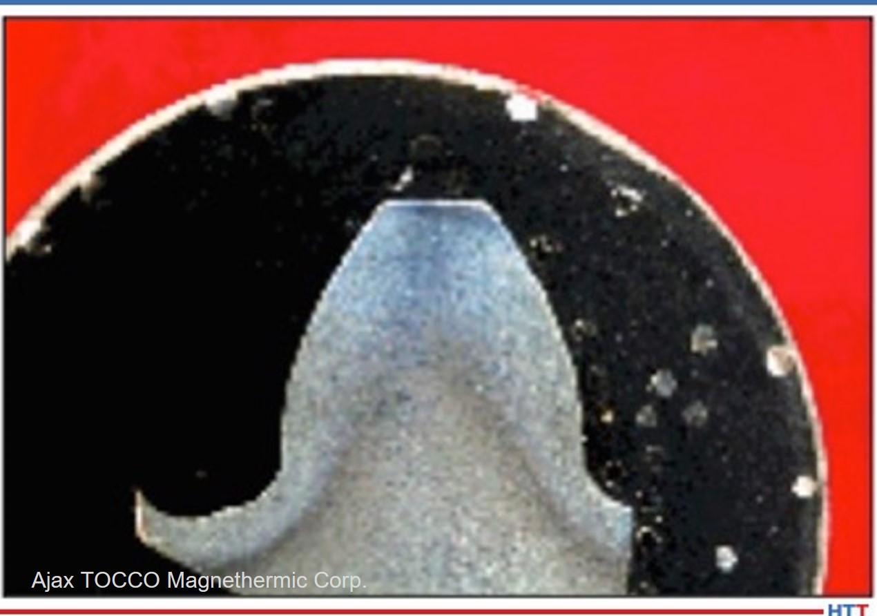
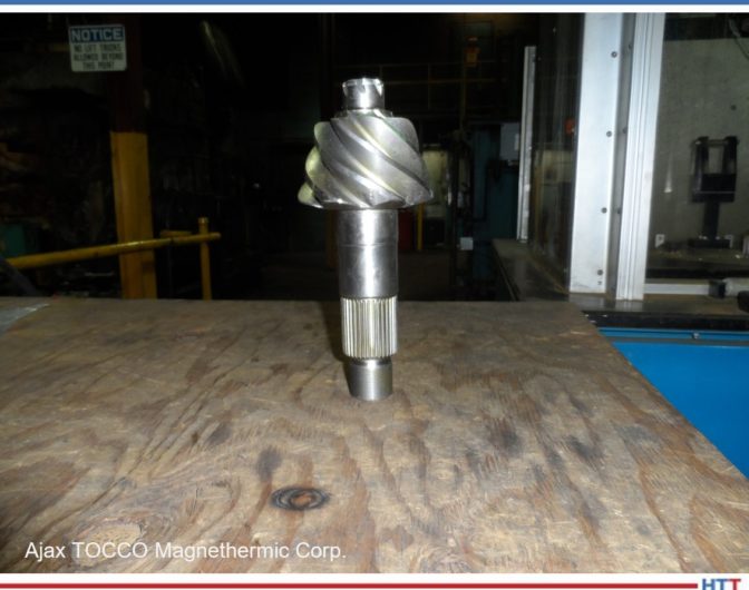
Induction hardening is commonly used to heat treat gear teeth, shafting, and other parts that require a high surface hardness for wear or strength. The process uses a power supply, RF generator, induction coil, and quenching mechanism (spray or immersion) to yield a high surface hardness and advantageous residual surface stresses. Heating is very fast, with selective heating of the desired part. An induction hardening line can be integrated readily into cellular manufacturing.
There are many problems that can occur in induction hardening that can have nothing to do with the power supply, RF generator, or coil. These are process-related issues that are often due to improper or inadequate process control. These problems can manifest themselves as improper part hardness or cracking; improper pattern; quenching issues such as foaming or excessive drag-out; corrosion issues; or biological issues such as bacteria and fungus or odors. In this short article we will discuss proper process control of polymer quenchants.
Concentration Control
Concentration control is one of the most important process parameters in induction hardening. Improper control can result in soft parts, cracked parts, or excessive distortion. The concentration of the polymer can change due to quenchant drag-out during operation, or due to evaporation of the water. Another source of inaccurate polymer control is contamination from coolants, or process fluids from prior operations if the parts are not cleaned prior to induction hardening.
The most common method of concentration control is by handheld digital or analog refractometer. A small drop of the quenchant is placed on the sample window of the refractometer, and the refractive index (in °Brix) of the quenchant is determined. The refractometer reading is then multiplied by the factor associated with the quenchant to determine the concentration.
However, contamination from using hard water, or other contamination from coolants, etc., can cause the factor to shift lower, resulting in an error in concentration measurement. The refractometer should be verified using kinematic viscosity at routine intervals, to monitor and correct the proper multiplying factor.
If the concentration is low, the polymer should be added. If the concentration is high, the water should be added.
pH
pH is the measurement of the acidity of the solution and is a measure of the health of the system. It infers the presence of adequate corrosion inhibitor. Steel parts tend to rust when solutions are at a pH of less than 7 and have a passive film at a pH greater than 8.5. Further, biological growth is stunted as the pH is increased. Contamination, especially by chloride containing coolants, or from water containing high levels of chloride can result in the pH dropping, and rust occurring. In water, when evaporation occurs, the chloride will concentrate. Should the pH drop below 8.5, then a pH booster or corrosion inhibitor should be added to increase the pH.
Corrosion Inhibitors
There are two types of corrosion inhibitors commonly used in polymer quenchants — nitrite/nitrate corrosion inhibitors, and amine based corrosion inhibitors. These different types of inhibitors should not be mixed due to incompatibility. Most machining coolants contain amine type of inhibitors, so this type of inhibitor is usually recommended for induction hardening unless the parts are thoroughly cleaned and rinsed prior to induction hardening.
Biological Availability
Biological activity, such as fungus or bacteria, can affect the performance of the quenchant. This generally affects the quench system by clogging filters, and clogging quench spray heads. It is also an odor issue, resulting in a strong mildew or rotten egg smell.
The test for biological activity is usually a simple dip slide. The slide, containing an agar-type growth medium, is washed with the fluid, and allowed to sit for three days. Bacteria growth will be evident on one side, and fungal growth is visible on the other side. The levels of bacteria are usually rated from 1–11, indicating bacteria or fungus in a logarithmic scale. When the bacteria exceed 6 or 106 CFU/ml, the fluid should be treated with a biocide. If the fungus count exceeds 102 CFU/ml, then it should be treated with a spectrum fungicide. The system should also be thoroughly cleaned prior to dumping and recharging to prevent contamination of the new bath.
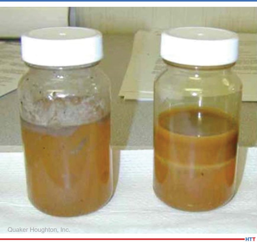
Image: Polymer quenchant contaminated with coolant. Failure to properly wash and rinse parts prior to induction hardening can contribute to rusting, cracked parts, and unsightly surface condition. Source: Quaker Houghton, Inc.
One thing to note, is that the use of biocides is extremely hazardous. Very small quantities (ounces) are required to kill the biological activity in a 10,000-gallon tank. Proper safety equipment (Tyvek suit, chemical safety goggles, face shield, and chemical resistant gloves) should be used to dose a system to kill biologicals. The use of biostable quenchants, such as Aqua-Quench™ 145 or Aqua-Quench™ 245 can avoid the use of dangerous biocides.
Contamination
Contamination is the most common cause of quenchant failure in induction hardening. This is due to improper or inadequate cleaning of parts prior to induction hardening. The contaminants do not burn off , but act as a source for rusting and other surface defects.
The quench tank is not a cleaning tank. Parts should be free from coolants and other fluids prior to heat treatment. Even a small amount of residue on each part can build up in the system, and thousands of parts are processed. For long life of the quenchant bath, proper cleaning of parts is required.
Conclusions
In this short article, the importance of several key variables was illustrated. Proper control of these variables will lead to properly heat treated parts, and long quench bath life.
About the Author: D. Scott Mackenzie, Ph.D., is senior research scientist in Metallurgy at Quaker Houghton. In 2008, he was awarded the Materials Science and Engineering Departmental Distinguished Alumni award from The Ohio State University. He is the author of several books, and over 100 peer-reviewed papers. Scott received a B.S. in Metallurgical Engineering from The Ohio State University and holds an M.S. and Ph.D in Metallurgical Engineering from the University of Missouri. He has served on the ASM Heat Treating Society Board of Directors, and is past president of the International Federation of Heat Treating and Surface Engineering.
For more information: scott.mackenzie@quakerhoughton.com
Find heat treating products and services when you search on Heat Treat Buyers Guide.com
There is an age-old adage that exists in the heat treating world. That supposition states that “the smaller the vacuum furnace, the faster it will quench.” Is this adage true? Explore Solar Atmospheres’ journey as they designed an experiment to discover if pressure or velocity most affects cooling performance.
This Technical Tuesday was written by Robert Hill, FASM, president, and Gregory Scheuring, plant metallurgist, both from Solar Atmospheres. The article originally appeared inHeat TreatToday’sMarch 2022 Aerospace Heat Treating print edition.
Introduction
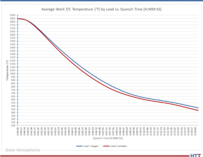
Our study compared the cooling rates of two distinctly sized High Pressure Gas Quenching (HPGQ) vacuum furnaces — a large 10-bar vacuum furnace equipped with a 600 HP blower motor versus a smaller 10-bar vacuum furnace equipped with a 300 HP motor. Both furnaces, one with a 110 cubic feet hot zone, the other with a 40 cubic feet hot zone, were exclusively engineered and manufactured by Solar Manufacturing located in Sellersville, PA.
History
High Pressure Gas Quenching in the heat treatment of metals has made tremendous strides over recent years. Varying gas pressures within the chamber have been shown to be more governable than their oil and water quenching counterparts. The number one benefit of gas cooling versus liquid cooling remains the dimensional stability of the component being heat treated. In addition, using gas as a quench media dramatically mitigates the risk of crack initiation in a component. This is primarily due to the temperature differentials during cooling. Gas quenching cools strictly by convection. However, the three distinct phases of liquid quenching (vapor, vapor transport, and convection) impart undue stress into the part causing more distortion (Figure 1).
Figure 1. Three phases of liquid quenchants Source: Solar Atmospheres
There are multiple variables involved with optimizing gas cooling. These include the furnace design, blower designs, heat exchanger efficiency, gas pressure, gas velocities, cooling water temperatures, the gas species used, and the surface area of the workpieces. Whenever these variables remain constant, the relative gas cooling performance of a vacuum furnace typically increases as the volume of the furnace size decreases.
The Furnace
Solar Manufacturing has built multiple high pressure gas quenching furnaces of varying sizes over the years ranging from 2 to 20-bar pressure. We have learned that vacuum furnaces, rated at 20-bar and above, became restrictive in both cost constraints and diminishing cooling improvements. Therefore, Solar Manufacturing engineers began to study gas velocities to improve cooling rates. They determined increasing the blower fan from 300 HP to 600 HP, along with other gas flow improvements, would substantially increase metallurgical cooling rates. The technology was reviewed and determined to be sound. A 48” wide x 48” high x 96” deep HPGQ 10-bar furnace, equipped with this newest technology, was purchased by Solar Atmospheres of Western PA located in Hermitage, PA.
Image 1. HFL50 furnace (36” x 36” x 48”)
Source: Solar Atmospheres
Image 2. HFL74 furnace (48” x 48” x 96”) Source: Solar Atmospheres
The Test
Image 3. Test load with thermocouple placement Source: Solar Atmospheres
Once this new vacuum furnace was installed, a cooling test was immediately conducted. A heavy load would be quenched at 10-bar nitrogen in an existing HFL 50 sized furnace (36” x 36” x 48”). The same cycle was repeated in the newly designed vacuum furnace almost three times its size! (Images 1 and 2).
The load chosen for the experiment was 75 steel bars 3” OD x 17” OAL weighing 34 lbs each. The basket and grid system supporting the load weighed 510 lbs. The total weight of the entire load was 3060 lbs. Both test runs were identically thermocoupled at the four corners and in the center of the load. All five thermocouples were deeply inserted (6" deep) into ¼" holes at the end of the bars (Image 3). Each load also contained two 1" OD x 6" OAL metallographic test specimens of H13 hot working tool steel. These specimens were placed near the center thermocouple to ensure the “worst case” in terms of quench rate severity. All tests were heated to 1850°F for one hour and 10-bar nitrogen quenched.
Results
The comparative cooling curves between both HPGQ vacuum furnaces are shown in Chart 1. Table 1 reveals that in the critical span of 1850°F to 1250°F for H13 tool steel, the cooling rate in the larger furnace with more horsepower nearly matched the cooling rate of the furnace three times smaller in size.
Table 1. Critical cooling rates for H13 (1850°F –1250°F) Source: Solar Atmospheres
Chart 1. Average quench rate for five thermocouples Source: Solar Atmospheres
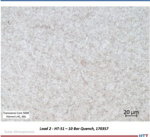
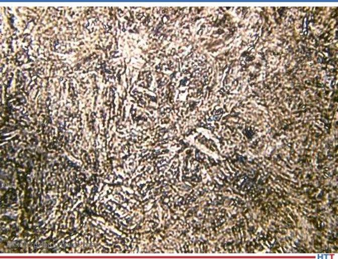
Micrographs of the H13 test specimens processed in each load were prepared (Images 4 and 5). The microstructure of each test specimen is characterized by a predominantly tempered martensitic microstructure with fine, undissolved carbides. The consistency of the microstructure across both trial loads further demonstrates that while the larger furnace utilized the higher horsepower, both resulted in a critical cooling rate sufficient to develop a fully martensitic microstructure.
These tests prove that the greatest impact on the cooling performance in a vacuum furnace is to increase the gas velocity within that chamber. This was achieved primarily by increasing the horsepower of the blower fan. By doing this, the ultimate cost to the customer is significantly less than manufacturing a higher pressure coded vessel. This newly designed vacuum furnace has proven to be a game changer.
Part II of this article will discuss real life case studies and how both Solar and Solar’s customers have mutually benefited from this newest technology.
About the Author:
Robert (Bob) Hill, FASM President Solar Atmospheres of Western PA Source: Solar Atmospheres
Robert Hill, FASM, president of Solar Atmospheres of Western PA, began his career with Solar Atmospheres in 1995 at the headquarters plant located in Souderton, Pennsylvania. In 2000, Mr. Hill was assigned the responsibility of starting Solar Atmospheres’ second plant, Solar Atmospheres of Western PA, in Hermitage, Pennsylvania, where he has specialized in the development of large vacuum furnace technology and titanium processing capabilities. Additionally, he was awarded the prestigious Titanium Achievement Award in 2009 by the International Titanium Association.
Quenching is typically associated with oil, water, or high pressure gas quenching. But Bill Disler from AFC-Holcroft suggests that we not forget about salt quenching. It is good and it is green. Listen as he and Heat TreatRadio host, Doug Glenn, walk through the benefits and drawbacks of an oft-forgotten form of quenching.
Below, you can watch the video, listen to the podcast by clicking on the audio play button, or read an edited transcript.
The following transcript has been edited for your reading enjoyment.
Doug Glenn (DG): First time, welcome to Heat TreatRadio.
Bill Disler (BD): Thank you very much, Doug.
DG: It’s good to have you and it’s about time we had you here. I’m pretty sure, this is your first time on Heat TreatRadio, but you’ve written several articles for us, all of which have been very well received, so we appreciate that.
If you don’t mind, give our listeners a brief introduction to yourself and your history in the heat treat industry.
Doug Glenn, host of Heat Treat Radio, and Bill Disler, president and CEO of AFC-Holcroft, talk about the goodness and greenness of salt quenching.
BD: Sure. I started out in heat treat back in 1987 I’ve been in the industry for quite a while. I came out of college with an electrical engineering and math computer science degree and ended up working at Holcroft back then. After a short period of time as an electrical engineer, I ended up over in China helping debug some control systems and my 6-week stint turned into 2 years. It gave me a jump start with some appreciation hands-on with furnaces, building furnaces, pushers, continuous and batch and rotaries.
Over the years, I’ve done quite a few different things from managing an advanced controls group, estimating sales and had a little stint outside of heat treat with a German company called Dürr (when Holcroft was going through some ownership transitions) and that gave me a little bit of a nice perspective, I think, outside of heat treat, so when I came back to AFC-Holcroft (after they acquired Holcroft), it opened my eyes to some things. I love the heat treat world, but we’re not always the fastest moving with technology, so that gave me a little bit of an insight with what the automation lines for building engine blocks and heads and things were all about.
Along the way, I was president of ALD-Holcroft, which was a joint venture between ALV (the German vacuum carburizing group) that gave me a lot of insight into a different form of process where mainly atmosphere and vacuum carburizing and gas quench. On the way through the journey, I ended up in the corner office at AFC-Holcroft. I’m still an engineer and a little bit of a sales guy at heart, I think.
DG: How long have you been president of AFC-Holcroft?
BD: That’s a good question. I think it’s been about 8-9 years now. From before we went through the transition with the acquisition into the AICHELIN Group, which happened in July of 2016, which is already almost 5 years, I guess, and several years before that.
DG: Good, and you’re out of Wixom, Michigan in the Detroit area.
BD: We have plenty of global entities and partners, but home base for the engineering team and me is Wixom, Michigan. It is not very far from where Holcroft started in downtown Detroit in 1960.
DG: Let’s jump into our topic today. We’re going to talk about quenching. Heat Treat Today has down a lot of different articles on various types of quenching, most of them have been focusing in on either high pressure gas quenching, oil quenching, and maybe some polymer water type quenching. We’re going to talk, today, primarily about salt quenching, but, if you don’t mind, give us the 30,000-foot view on some of those more chic, popular, newer types of quenching, if you would.
BD: Quenching, obviously, is for our customers and our listening group and, I assume, one of the most critical things in a lot of our heat treat processes. Since I’ve been involved in heat treat, which has been a few years, there has always been focus on different types of medias to quenchant. Over the years, I’ve come to look at quenching as a basic thermal heat transfer process. As we talk about salt eventually, we can talk about some of the other processes and some of the fundamentals that people don’t always understand about, say, oil. Frankly, we, and the general population of people that carburize and quench, generally it’s oil that’s the common quenchant. It is still, far and away, the most popular from anything else out there. Oil is a very flexible quenchant. It’s tried and proved. It’s predictable. But it does have one challenge and, I think, this ties into the evolution into gas quenchant.
The challenge with oil is it boils. As you take a hot part and put it into oil, the reason we all focus of quench agitation, too much speed and too little, is to try to take the oil past the part before it boils. The reality is you just can’t do that. You can help it, but there is always going to be a vapor phase. The challenge with that is the non-even heating of heat transfer into a liquid versus heat transfer into a gas is significantly different. You’ve got two phases with oil that you’re quenching the parts into. What’s probably the most common concern with quenching is distortion.
Over time, I think, that’s the introduction of gas quench. The evolution of trying to control distortion is mainly from oil, I’ll call it a two-phase quench, where you have liquid, heat transfer and a gaseous heat transfer taking place to a single-phase quench. When you compress gas, it’s already a gaseous phase. If you get into an 18-bar quench, say, the higher the pressure, the better the heat transfer, but it’s a single-phase quench which means, generally, you don’t have that big differential and temperature when you’re quenching parts, so your distortion tends to improve.
The challenge with gas quenching is that even at higher pressures, 18-bar or reasonable pressures, in a cold chamber going from a hot chamber to a cold chamber quench (like on the larger systems that are used in some of the automotive gears) the heat transfer coefficient is still not very good so you’re just not able to take enough heat away fast.
That was really the big evolution in the introduction of gas quenching, which I tend to talk about separate from vacuum carburizing. But the gas quench element was all about distortion control. Transmission gears in automotive, they were hoping to go from oil quench, where they had to get the distortion and hard grind them (which is very expensive), to gas quench and then they wouldn’t have to grind. The reality is, generally, they still grind today, but the gas is a better heat transfer media when it comes to distortion in oil because it’s single-phase. It just can’t take a lot of heat out fast. That’s where we’re seeing salt come back into the picture, even for martensitic-type quenches.
If we look at that evolution, we went from oil to gas quench for distortion, but now, a lot of the challenges people are seeing are that the heat transfer rate limitations (you’ve got to go to very light trays and carbon fiber fixtures and things like this) it’s got its limitations. Also, for certain parts, it could just be too thick to take the heat away quick enough to be successful. The other big thing is, it’s not cheap. You’ve got very complex high-pressure chambers, 300-horse motors and so on.
DG: Right. You’re sucking down the electricity, we know that for sure, with the high horsepower motors, typically.
BD: Yes, and unfortunately, they must cycle. In a big plant, it’s one thing having a lot of power consumption, but it’s another thing where you have these high horsepower motors starting and stopping all the time. It’s not usually things that our customers like, but clearly, it’s an acceptable heat transfer quench system, and for the right set of parts, it can be a very good fit. I think that we’ve gone through an evolution where a lot of customers went from one type of quenching into this and we’re seeing a lot more activity with them saying, “Wow, you know, we really like the distortion control, but what else is there?” This is where salt starts coming back into the mix.
DG: Which is what we really want to talk about. I think that’s probably a good segue, Bill, to get over into it. Salt quenching. What is it? I don’t know that a lot of people use it, so please explain it for the uninformed.
BD: A lot of people I’ve known in the heat treat industry for a long time, when I bring up salt, they ask, “Why are you bringing up salt? That’s nasty stuff. We don’t want to use that.” First, I guess I should start out saying we’re talking about salt quenching. Historically, when people talk about salt, they talk about high temperature salts, as well, that had cyanide and things like this in it. Nasty animals.
DG: For salt bath heat treating, is how you’re heating it up, but we’re not talking about that.
BD: Correct, we’re not talking about that. We’re talking about using conventional atmospheric equipment and then quenching instead of oil or polymer or gas or something else and taking it into molten salt.
I’d say, in general, the most common thoughts with salt are to use it for bainitic quenching. If you’re quenching into a bainitic structure, salt has always been the only way to do this.
“If you’re quenching into a bainitic structure, salt has always been the only way to do this.” -Bill Disler Photo Credit: Metallurgy For Dummies
The reason is you can take it up into the temperatures where you form bainite, which I’ll say is often 600 or 700°Fahrenheit, where they’re using salt to quench into a bainitic structure versus martensite which is a lot of our conventional heat treat. I’ll call it a bit of a specialized process, but it’s very common. All your spring steels and a ton of parts are better bainitically quenched.
In general, you’ll see a lot of mesh belts doing stamped parts in a molten salt. Most of those are in the bainite — spring clips, retaining clips and things like that. But you also have batch systems that have the ability to quench into salt-type environments. Still, I’d say the majority are in the bainitic quench. But what we’re seeing the growth into, and much more activity, is martensitic quench. I’ll just say “transmission gears” for the sake of an example. What people might not realize, and it wouldn’t be appropriate to name the company, but one of the big three in the day, an American automotive company, prior to going to gas quenching, back in carburizing, all of their transmission gears were quenched into salt. Rows and rows of pusher furnaces into salt quench to get martensite. The benefit of that, that they saw -- and I’ll say that these lines were built in the ‘70s and the ‘60s -- so this isn’t new, they were using molten salt to get martensitic quenching in transmission gears because it was less distortion than oil. Then, their evolution was to go into with some of the German dual clutch transmissions came gas quenching.
Interestingly enough, some of those folks are now saying, “Wow, that was really expensive. I’ve got this equipment for 10+ years and maybe I should revisit some of the other stuff that used to give us the same distortion in martensitic.” This, I think, is the journey that salt has gone through. It is not a new process; it’s been around for a lot longer than I’ve been in the business. But it does have a stigma of "dirty" which is, I think, maybe unfair. And, if it’s confused with high-temperature salts, then it has an environmentally unfriendly feel to it.
DG: I want to talk about that. I want to talk about the “greenness” of it in just a second.
You’ve given us a sense that it’s been around for quite a while, salt, and salt quenching, but let’s talk about some of the advantages.
BD: To me, sometimes it’s easier for somebody to be able to visualize what’s happening in a quench and then these pieces fall into place. Let’s say you used the example of parts with significantly different thicknesses. They can be challenging for any kind of quench media. But the big thing that causes distortion and can cause different problems is the vapor phase of oil. So, we’re going to compare to oil. If you think about the things that happen when you get a vapor film or some bubbling on the surface of a part, it’s all about uneven heat transfer. I use the example of — if you want to take something out of your freezer and thaw it, you have to sit it on your kitchen counter in the air and how long will it take to thaw or put it in some water. It’s a radical difference in heat transfer between a gas and a liquid. This is what happens when you get a film boiling with oil. We do a lot of things to minimize that, that’s quench agitation. But if you have a big, thick piece of material here and a thin piece here, this is going to give up its heat quick really quick, this one may not. You’ve got to get into the core that you’re still taking heat out. There’s a heat transfer rate and I’d say that salt, at a quenching temperature of maybe 350 degrees, is going to have, roughly, about the same heat transfer rate as oil. It’s not about heat transfer as much as the fact that it is all uniformly cool.
Even if the heat treat transfer coefficients of oil versus salt were similar, the reality is, in a quench you’re not getting the liquid heat transfer rate in oil in all aspects of the part, and so those areas cool much slower, where salt won’t boil. That’s the key: salt doesn’t boil in the temperatures we’re dealing with so it’s always a liquid heat transfer rate.
DG: Right. In a sense, with oil, you think you’re dumping it into a liquid, but the fact of the matter is, for some fractions of a second or fractions of a minute, you actually have a gas quench going on there, if you will, because of the vapor, right? You’ve got an insulating layer there that is preventing the liquid from actually hitting the metal, so you’re getting ununiform quenching.
BD: Yes. Let’s say you’ve got a ring gear or something. Like everybody, you’ve got flow of oil coming into the bottom. You might be getting nice liquid heat transfer here, but what’s on the other side where you’ve got a little less flow and you’ve got a bigger vapor barrier on that side and, guess what? that’s what makes the gear bed. So, whether or not we’re talking about a gas quench or a salt quench, the characteristics of the quenchant are the same, they’re a single phase and that brings a huge amount of benefits in heat transfer. You could talk about something like a “blind hole,” it’s hard to quench a blind hole. As an example, it’s hard to carburize or quench a blind hole. That’s one thing. Let’s say, for instance, in a blind hole, a good argument for vacuum carburizing, if that’s a big issue and you need to carburize inside of it, because vacuum carburizing can probably get inside more than endo. But when it comes to quenching, they’re hard to get into either way, but imagine oil getting into a hole that’s very hot.
What’s going to happen? You’re going to get boiling in that hole. I’m not saying that salt’s going to cure all those problems, but you don’t have it boiling trying to get into the hole. You’ve still got to get the fluid into the hole, which is a problem, but you don’t have the vapor that’s pushing it back out. In those cases, it’s very much a case by case. I think that the physics of salt, and if people can visualize what’s happening when you’re quenching, it’s not magic, it’s just that it’s a single-phase quench and that brings a lot of benefits. It’s a single-phase quench with much better heat transfer rates than, say, 18-bar nitrogen. This is where you can use it in places where you can’t gas quench a part. If you’ve got a thicker part and you can’t get the heat out of it in the gas quench, you may very well be able to get the distortion benefits from salt, but still get the heat transfer rate that you need to quench out the part.
DG: One of the things you mentioned, Bill, with oil, was that the reason you engage in a lot of the stirring of the quench, the agitation, and things of that sort, is to help keep that to, hopefully, eliminate the vapor stage and keep the oil flowing over the part, so that helps with the distortion. Do you have to do the same thing agitation-wise with salt or do you do the same thing with salt? Do you agitate to quench, as well?
BD: We still want to be moving the salt past the parts just like any media. It’s not as much a worry about boiling, but we’re still transferring heat into the salt. You want to take that heat and move it away from the parts. Agitation is the vehicle to do that. You were talking about uniformity before, the tank uniformity of a salt quench versus an oil quench, it’s all about the same. We can hold uniformity throughout. The bigger thing is instantaneous temperature rise with the quench which is a different topic which is really a function of the volume of the tank. I’d say, we still want to move, in most cases -- and it’s not as sensitive if you’re in a mesh belt where you’re dropping parts down through a tank, you might not need that agitation -- but, in a batch or a fixtured, continuous load, we definitely would want to still agitate the salt.
DG: Primarily, to keep the cooler salt, if you will, coming by which therefore can increase your heat exchange and heat extraction.
BD: Right. Your heat transfer rate would stay constant because you’ve got the same temperature salt through it.
DG: I’ve got one other quick question: Oil quench runs typically at what temperature? What temperature do you keep the oil quench bath and what temperature do you keep the salt quench? Are they roughly the same?
BD: No, they can be significantly different. It depends on lots of things, but I’ll say that we typically see oil running from 120–150°Fahrenheit up to 350°Fahrenheit. In fact, we’ve had customers run over 400°Fahrenheit with special oil, but generally, you’re up into the flashpoint of the oil and it’s not really a great idea. Those are all martensitic quenches. Remember, oil can’t get you bainite; you can’t go high enough in temperature to get a bainitic quench. If you’re quenching it to bainite in salt, which is still very common, you’re above the martensite start point for materials which, of course, depends on the alloying of the material, call it 400°Fahrenheit, roughly.
Above those temperatures, salts are very comfortable, and they’ll run up to 800° with no practical limit, but there is no need to go much higher than that for bainite. If you wanted to get into martensitic quenches, you’re going to be down around the 300-degree temperatures. You can’t go to lower temperatures with salt. Your realistic lower point would be about 300° which I tell anybody looking at it, you’ve really got to look at your parts, your alloy and everything else to make sure it’s still a fit. But, in most cases, that can give people what they’re looking for. It’s not a “one size fits all.”
DG: Right. That was one of my questions: Just how low can you go?
BD: You could, arguably, go down to maybe 250, but the lower temperature salts don’t behave that well, so I’d say probably in the 300–350° range. That is also probably for a customer that is looking to optimize distortion control, as long as they can get the hardenability at those temperatures of their materials and so on. That’s probably the sweet point for trying to minimize distortion. But it is always a balancing act because you’re still at a temperature that is higher than some of the colder oils. There could be some parts that simply may not be a great fit, that’s why we have to look at them on a case by case.
"The other big thing that’s very important is that in the current systems, we reclaim close to 99% of the salt. If you look at an oil quench, you go into an oil quench, you come out, you wash the oil off, and it ends up in a washer kind of messy and homogenized and we have skimmers of various types and then you get this sludge that you must get rid of." - Bill Disler, AFC-Holcroft
DG: Another thought that jumps to mind is that you don’t have a flash point with salt, I assume.
BD: Not in the temperatures we’re working with.
DG: Is salt quenching green?
BD: Yes. As we said before, I think the first reaction of the average listener when I say, “yes” is: That guy doesn’t know what he’s talking about! We’re dealing sodium nitrite/sodium nitrate salts. I won’t go so far as to say it is exactly what your table salt is, but it is not that different. There is no cyanide in it, there are no "nasties" in it. Depending on where you are, small quantities can probably go down the drain, some places not. You’re not going to dump down a bunch, obviously, but it is not like oil.
The other big thing that’s very important is that in the current systems, we reclaim close to 99% of the salt. If you look at an oil quench, you go into an oil quench, you come out, you wash the oil off, and it ends up in a washer kind of messy and homogenized and we have skimmers of various types and then you get this sludge that you must get rid of. With salt, you’ll come out of the quench with some liquid salt on it, you’ll go into a washer but that salt then dissolves back into the water. Generally, there is a multiphase wash with a wash/rinse/rinse. Then, after we get a certain percentage of salt in the wash solution, we thermally evaporate the water off leaving the salt back where it can be reintroduced into the quench tank. When you look at it from that standpoint, salt is reclaimed.
Oil, unless you’re really getting into high-tech thermal recovery for oil, is not friendly to get rid of. The other thing is, you’re recycling your salt. You’ve got to load it up once, but you don’t have the life expectancy problems, typically, with salt. You can rejuvenate it, you can mix your balances over time. Oil, yes, you can recycle oil and do additives, but if someone is picky about their heat treat, after a year or two, you better be dumping the oil and starting all over again. Where does that oil go? It’s contaminated oil. From an environmentally friendly standpoint, as ironic as it sounds to some people, salt is a very, very green process. We recycle almost all of it.
DG: On-site, too. It sounds like when you’re recycling or reusing it, you’re able to do most of that on-site whereas a lot of people are sending oils out, right? They’ve got to send them out, get them tested and all that good stuff.
BD: Yes, this is all on-site, so you have a recovery system, whether it’s a batch or a continuous-type operation, you can recover the salt. From an environmental standpoint, it is much greener. We’re trying to let people know that because there is a lot of movement to environmentally friendly heat treat, whether we start seeing more electric furnaces or not, we’ll see, but the carbon footprint has to be looked at, but quenchant is one of them that has a bad rap.
DG: Yes. I was watching the other day about the first batch of completely green steel was delivered to a car company and manufactured--or maybe it was an off-road vehicle company like Caterpillar or somebody like that--and they had made their first fully "green" piece of equipment from green steel that came from somebody. But you’re right, the point being: green is here.
BD: Green is here. That’s a bit of the benefit, I would say, over oil to gas quench, as well. I think we’ll be seeing more. All of the people in the furnace manufacturing world will soon be delivering carbon footprint data on furnace information. A lot of our customers are already looking for that. It’s already in Europe, but it’s coming to the U.S. as well. What’s interesting is we start comparing our experience with LPC and gas quench. With electricity, now we’re tracking to where you’re making the electricity. If it’s from a coal plant or a natural gas plant, there is still a carbon footprint to it. I think as we unravel these complicated topics, it will be interesting to see how well conventional atmosphere, and something like salt, fairs in that comparison.
It’s interesting, but people forget, even with vacuum furnaces, which we’ve built quite a few of, they are water cooled. Water cooling and pumping water through stuff that you have to put additives in and everything else is not environmentally friendly. The irony is, over my career in atmosphere furnaces, there has been an ongoing push to get all the water off of the furnace. It used to be water cooled fans, water cooled doorframes; I don’t want any of that now. It’s all air cooled. Even endo-generators. Then, here you go in this new environmentally green system and you’re pumping tons of water around. As we started doing some comparisons with salt, oil, and all of the other systems that we offer, it is coming out interesting what is really green and what the perception has been out there.
DG: I think that’s generally true for most of the green movement is what’s perceived to be green and what might really be green is a different thing. If you read in our August issue, we had a column by Lourenco Goncalves who is the chairman/president/CEO of Cleveland-Cliffs and he had very interesting things to say about what people think is green and what really is green.
What’s perceived to be green and what might really be green is a different thing. Like Kermit the frog said, "It’s not easy being green!" Photo Credit: LoggaWiggler at Pixabay.com
BD: It’s an interesting topic and a sensitive one. We’ll be hearing more about it, I’m sure.
DG: On a completely serious note, here: When I graduated from high school in 1980, our class song was Kermit frog singing "It’s Not Easy Being Green." Now we know, it isn’t easy, actually! Most companies will tell you, it’s not so easy. So, Kermit had something there. He was a man (frog?) ahead of his time.
One other environmental question for you about the salt quenching: How about the work environment around salt? Is there off gassing? Is there anything hazardous to workers near it? If you work near a salt bath furnace, forget it, come in with a facemask on. But how about salt quenching?
BD: We’ve got an austemper heat treat (it’s just belt austempering) up here in the Detroit area. If you walk into that plant, it’s incredibly clean. You don’t have the oil fumes, vapors, and things like that, which in any plant, if it’s properly vented and so on, isn’t a big deal, but you don’t have that feel to it. There is nothing toxic about it.
But it’s like any other quenchant: If you’re operating oil or salt at 300° or above, you’ve got to take care. Whether it’s oil or salt, they don’t mix well with water because it’s above the boiling point of water, as an example. I’d say in those areas, those two have similar challenges, it’s just a matter of dealing with a hotter quenchant.
The one challenge with salt -- and these are "conventional"/a bit older equipment -- is the carryout. When you carry out salt as molten, when it cools down it solidifies on the surface. Instead of getting a little grease and/or oil on your transfers, you can get solidified salt. It’s not fun or desirable. So, with salt, if you’re in a batch line, for instance, it’s more pronounced and you do have to have some special maintenance procedures to rinse down your transfer car and things like this. As long as you do that, it’s very easy to maintain. The reality is, you’re coming out of a hot quench, and when you get it onto a transfer car to get to a washer, it can solidify. Once you get to the washer, then it’s easy street. In your continuous furnaces, it’s really not an issue because you’re going right from one area right into a washer and it’s much more contained. The reality is your batch systems can get a bit messier. If you’re then taking, say, a hot load that was quenched to a bainitic temperature and putting it into a washer, you could be putting a 600°Fahrenheit load into a washer and you get a lot of steam.
The challenge is, if you don’t contain the steam, the steam can contain salt in the vapor. Just like oil can be in vapor, too, but it’s just a different animal. You don’t want that any more than you want an oil vapor. It can stick on different things. I would say that would be the one reality about salt in batch. The newer systems and things that we focused on is overcoming that. For instance, by quenching in salt (if it’s not batch) moving directly into a multistage washer before that load even comes out onto a transfer so there is no carryout of salt. By the time the parts come out, they’re perfectly clean. The nice thing is, remember, washing salt off of a part with water versus washing oil off with water, another big topic maybe you’ve had some podcasts on is washing oil.
“There is nothing toxic about it.” -Bill Disler Photo Credit: BRRT at Pixabay.com
You know that story of oil and water don’t mix? Well, they don’t. However, salt and water do mix. Salt goes into solution in water, and we carry it away and you’re going to get nice, clean parts. That’s another nice byproduct of a system designed properly. In the older days of those old big pusher furnaces, one of the automotive companies was making transmission gears — those were open salt tanks. So, we’ve come out of a furnace into an open salt tank and then you’d bring it up and take it into the washer and the temper. Along the way, you had all kinds of salt buildup. You must remember, those were about 50 years old. So, the key is designing equipment to manage it differently containing those wash fumes and things like that.
That’s what we see the next evolution of salt quench systems being because we do see salt becoming more common, definitely asked for after the people have had their interests with compressed gas quenching and distortion control. Now that it’s coming back, we really need to think about repackaging it to keep it clean in the plant.
DG: With every system, whatever it is, there is maintenance involved. Are there any special maintenance requirements on a salt quenching system?
BD: Yes. I’d say it’s different than a conventional oil quench system. Any quench system that you’re looking at has its uniqueness to maintenance. Salt can be something that needs to be learned a bit if it’s new to somebody. We talked a little bit about the risk of salt solidifying and creating a mess, so you have to rinse it down. As I said, in a transfer car, in a batch situation, we normally would suggest a parking station where you can rinse that car down very easy. You do have to look for salt buildup on some of the systems. It is not difficult maintenance, but you have to be attentive to it.
The one thing I’ll say is a benefit with oil in some cases, when you have carryout, it gets all over your equipment, it’s a lubricant. It’s messy, it’s undesirable, but it’s a lubricant. . . until a bunch of other stuff gets tied into it and then it can be an abrasive lubricant. Salt doesn’t bring you that benefit. So, you have a little bit more housekeeping. There are a lot of recommendations on how to do that.
Also, generally, for a quench system, we would recommend a holding tank that you can pump out the tank with versus some plants would use a tanker and have a company come in and pump out tanks. The reason for that is, if you had maintenance or if you had a different issue, you want to try to keep that salt liquid. When you’re looking at things, if you were running a heat treat where you really wanted to shut it down for extended periods of time, bring it back up and so on, you had to look closely at salt because salt takes a while to re-liquefy once it solidifies. It’s not the kind of thing you turn on and off like one of the benefits of the gas quench- you can turn it on and off. Again, there is no one size fits all; it’s got a blend of benefits and some challenges, so it just depends on the operation itself.
DG: Is there danger in a salt quench system if power goes out and the salt solidifies? Are you going to ruin your equipment or is it just all froze up and now needs heated back up?
BD: We would recommend pumping it into another tank. But if, in fact, it was to solidify, you just have to take the time to re-melt it when you get power back.
DG: Okay. It’s not like ice, I assume; it doesn’t expand and crack you tank.
BD: No, it’s not going to blow up or anything.
DG: Let’s move into a practical question about applications. I have a two-part question. First, what are some typical applications for salt quenching, and then, secondly, are there products and/or processes that people are doing that they not ought to even think about salt quenching? So, first, what are the good ones, secondly, what are the ones we shouldn’t think about?
BD: Again, I take salt quench applications into two categories. The most common, that we talked about earlier, are bainitic quenches — austempering and things. We even see it now becoming more common- ductal iron austempering which is a slightly different process starting with a different material. The benefit of that, and we’ll see more and more of it, is it’s got a tremendous strength to weight ratio, even better than aluminum, as an example. It’s a great way to lightweight certain things. So, we have the whole world of bainitic quenching, which is pretty traditional with salt, but the less traditional would be the martensitic type quenching, or we’ll say more conventional to most of our people using oil.
One application we’re seeing a lot of activity with is in-gears. The reason for gears being something that people are looking close at because they’re so sensitive to distortion. Even when people went to gas quench, they found that to get quiet transmissions, they still did some light grinding. But, just to be clear, the less distortion you have, the less grinding you do. Grinding isn’t a nice process; you’re grinding away on some hard steel. That is something, especially when we look at electric vehicles coming out, some of those power trains are now spinning at much higher RPMs. Distortion is going to be even more sensitive to them and I suspect that salt could play a role for them, especially in some of the volumes if they don’t want to get into some of the complications and expenses of a gas quench type system.
"Recently, AFC-Holcroft got a patent on a quench severity probe which can measure that in salt. Whereas before there was no way to measure that, we can now, with a probe, see the change in quench severity with this technique within a quench tank so that it’s more repeatable." - Bill Disler, AFC-Holcroft
DG: How about people that shouldn’t even think about salt if you’re doing a certain type of product?
BD: Again, I think part of it is the application itself. Getting into salt, if you’re already in oil, is a commitment. There are a lot of benefits to it. There are going to be some parts where, maybe, you can’t get the heat transfer quenching down to 300°. If you need to be in a cold oil (a lower temperature quench) to get certain characteristics, salt is probably not going to be a great fit for you.
There are interesting things happening now with salt that may be worth mentioning and it’s been going on for a while, but, interestingly, we talk about vapor barriers and all this stuff, there are some people that add small amounts of water to salt. AFC-Holcroft has been doing a lot of research on this because the actual physics of how this works is kind of mystifying.
Even for austempering ductal iron, when you’ve got salt at 600-700°Fahrenheit, there is water often added to the salt to increase its quench severity. The question you obviously ask is, “Well, how the heck do you get water to stay in salt in anything over 212?” It does, in fact, happen. It stays in a liquid form (based on some testing we’ve done), whether it’s a combination of pressure and some other physics going on.
The interesting thing is, when we did testing with the heat transfer rate, it’s not just conventional water blend with salt to give you the heat transfer coefficient change with salt with a little bit of water in it, but it appears that as you do quench and there is water, it’s the latent energy that is needed to transfer the water into gas -- which is a little bit of something we’re trying to work against, right? -- that absorbs a lot more energy out of the material.
We know that water is a very severe quenchant so it can really change the quench severity of salt with small (we’re talking about 1-3%) water in salt. Recently, AFC-Holcroft got a patent on a quench severity probe which can measure that in salt. Whereas before there was no way to measure that, we can now, with a probe, see the change in quench severity with this technique within a quench tank so that it’s more repeatable.
It’s a complicated topic. If people want to follow-up and ask me some questions about it later on, I’m happy to talk about it.
DG: So, you patented this quench severity probe?
BD: Yes, we got a patent.
DG: I see another Heat TreatRadio in your future!
BD: We’ve got a few patents. I don’t talk a lot about them, but we’ve got some interesting things going on. That was one we started working on a couple of years ago because people, for a long time, added water to salt to change the quench severity, but it’s a very difficult thing to measure. Now, being able to look at means to measure in-situ is potentially an important ingredient in the next years for people that start transferring into this as a more viable quench option.
DG: One other question, really quick, and maybe a very brief answer: The parts that come out of a salt quench compared to the parts that come out of a high-pressure gas quench, how about the cosmetics of them?
BD: They’re not going to be as bright and shiny as coming out of a gas quench. I don’t think there’s anything out there right now that’s going to give you the same cosmetics as gas quench. If you have an application where that’s really important, gas quench is hard to beat. I will tell you there are pros and cons to that. First, a vast majority of parts that are gas quenched; gears, as an example, still go through a shot peening process. That’s not for cleanliness, it’s for surface strength.
The other thing is, as we’re working with ALD-Holcroft, a lot of these systems now have to etch the parts coming out of heat treat. The benefit of nice clean parts is they’re nice and clean. The downside when you’re managing a captive or commercial heat treat is you can’t tell a green part from an untreated part. Believe me, there have been some nightmares where that didn’t go well. And they all look the same. Ironically, for all the benefits that that has, it added in our lines in the gas quenching systems, etching the part so that you could tell, but it’s still not a perfect scenario. Again, if you need nice, clean parts, salt is not going to give you bright and shiny.
DG: Last question: If I am a captive heat treater currently using oil, currently using high pressure gas quench, what are the questions I ought to be asking myself about, potentially, transitioning back over to salt? How do I know my process is a good candidate?
BD: That’s a good question. There are ways that we can look at a particular material, type of part, and the big thing, first, is can we get the heat transfer rate to get the hardenability at the temperature that salt is able to quench at. If you vet a part through that process, you could then look at doing some testing with distortion and so on. If you could be a candidate for a hotter oil quench with your part, this is probably quite viable. If you need to get into cold oil with the heat transfer rates there, it’s worth doing some testing only because, again, sometimes you don’t know exactly what the true heat transfer rate you’re getting with oil is because it could be that vapor phase is playing a little bit of a game with you. Even though the textbook transfer rate of salt isn’t quite as good as it would be for an oil quench in that situation, it might bring benefits beyond just those static numbers, so we need to do some testing and things like that.
The big thing I will say is it’s not a plus to salt, but I’m here to be objective. We build all kinds of equipment not just salt quench. The one thing I’d say a captive work commercial needs to look at and it’s also a factor with the design of the equipment: We’ve been in a lot of heat treats, Doug, and I’m sure some of you go in there and you want to make sure you don’t have your leather-soled shoes on because everything has a film of grease on it from the oil.
The one thing that we tell customers is that if you’re going to put in salt, it’s better if you can have it in an area that is separate from your oil quenches. The reason is that, depending on the system, you can still get vapor if you don’t vent, say, a washer really well. You won’t get it off of the quench because it never boils. It’s, generally, the washer. In the older days you’d see steam coming out of a washer that looked like a leaky tea kettle boiling over. Those systems you’ve got to be careful because there is salt residue in that vapor.
Mixing salt residue with oil is not a good combination. The reason is oil will burn, it’s got the carbon in it; salt is an oxidizer. You really don’t want those two mixed because it can burn more aggressively and create more of a danger. One of the hurdles of people looking at salt is that it is not easy to just put in any old heat treat. If you’ve got an oil quench line, sticking a salt line right next to it, we wouldn’t advocate that.
The newer equipment we’re coming out with, we’ve got a new product that’s been developed to address that specifically (to contain any salt vapor), but the risk that people should look at is mixing salt and oil. If either one of them are allowed to go into vapor phase, you don’t want those two vapors condensating together because the salt can be your oxidizer to oil which wants to burn. For safety reasons sake, we would advocate trying to do this in a separate area. This can be a huge hurdle to a lot of people.
We’ve assembled some of the top 101Heat TreatTips that heat treating professionals submitted over the last three years into today’s original content. If you want more, search for “101 heat treat tips” on the website! Today’s tips will remind you of the importance of materials science and chemistry.
By the way, Heat TreatToday introduced Heat Treat Resources last year; this is a feature you can use when you’re at the plant or on the road. Check out the digital edition of the September Tradeshow magazine to check it out yourself!
Induction Hardening Cast Iron
Induction hardening of cast irons has many similarities with hardening of steels; at the same time, there are specific features that should be addressed. Unlike steels, different types of cast irons may have similar chemical composition but substantially different response to induction hardening. In steels, the carbon content is fixed by chemistry and, upon austenitization, cannot exceed this fixed value. In contrast, in cast irons, there is a “reserve” of carbon in the primary (eutectic) graphite particles. The presence of those graphite particles and the ability of carbon to diffuse into the matrix at temperatures of austenite phase can potentially cause the process variability, because it may produce a localized deviation in an amount of carbon dissolved in the austenitic matrix. This could affect the obtained hardness level and pattern upon quenching. Thus, among other factors, the success in induction hardening of cast irons and its repeatability is greatly affected by a potential variation of matrix carbon content in terms of prior microstructure. If, for some reason, cast iron does not respond to induction hardening in an expected way, then one of the first steps in determining the root cause for such behavior is to make sure that the cast iron has not only the proper chemical composition but matrix as well.
(Dr. Valery Rudnev, FASM, Fellow IFHTSE, Professor Induction, Director Science & Technology, Inductoheat Inc.)
14 Quench Oil Selection Tips
Here are a few of the important factors to consider when selecting a quench oil.
Part Material – chemistry & hardenability
Part loading – fixturing, girds, baskets, part spacing, etc.
Part geometry and mass – thin parts, thick parts, large changes in section size
Distortion characteristics of the part (as a function of loading)
Stress state from prior (manufacturing) operations
Oil type – characteristics, cooling curve data
Oil speed – fast, medium, slow, or marquench
Oil temperature and maximum rate of rise
Agitation – agitators (fixed or variable speed) or pumps
Effective quench tank volume
Quench tank design factors, including number of agitators or pumps, location of agitators, size of agitators, propellor size (diameter, clearance in draft tube), internal tank baffling (draft tubes, directional flow vanes, etc.), flow direction, quench elevator design (flow restrictions), volume of oil, type of agitator (fixed v. 2 speed v. variable speed), maximum (design) temperature rise, and heat exchanger type, size, heat removal rate in BTU/hr & instantaneous BTU/minute.
Height of oil over the load
Required flow velocity through the workload
Post heat treat operations (if any)
(Dan Herring, “The Heat Treat Doctor®”, of The HERRING GROUP, Inc.)
How to Achieve a Good Braze
In vacuum brazing, be certain the faying surfaces are clean, close and parallel. This ensures the capillary action needed for a good braze.
A good brazing filler metal should:
Be able to wet and make a strong bond on the base metal on which it’s to be applied.
Have suitable melt and flow capabilities to permit the necessary capillary action.
Have a well-blended stable chemistry, with minimal separation in the liquid state.
Produce a good braze joint to meet the strength and corrosion requirements.
Depending on the requirements, be able to produce or avoid base metal filler metal interactions.
(ECM USA)
Pay Attention to Material Chemistry
When trying to determine a materials response to heat treatment, it is important to understand its form (e.g., bar, plate, wire, forging, etc.), prior treatments (e.g. mill anneal, mill normalize), chemical composition, grain size, hardenability, and perhaps even the mechanical properties of the heat of steel from which production parts will be manufactured. The material certification sheet supplies this basic information, and it is important to know what these documents are and how to interpret them.
Certain alloying elements have a strong influence on both the response to heat treatment and the ability of the product to perform its intended function. For example, boron in a composition range of 0.0005% to 0.003% is a common addition to fastener steels. It is extremely effective as a hardening agent and impacts hardenability. It does not adversely affect the formability or machinability. Boron permits the use of lower carbon content steels with improved formability and machinability.
During the steelmaking process, failure to tie up the free nitrogen results in the formation of boron nitrides that will prevent the boron from being available for hardening. Titanium and/or aluminum are added for this purpose. It is important, therefore, that the mill carefully controls the titanium/nitrogen ratio. Both titanium and aluminum tend to reduce machinability of the steel, however, the formability typically improves. Boron content in excess of 0.003% has a detrimental effect on impact strength due to grain boundary precipitation.
Since the material certification sheets are based on the entire heat of steel, it is always useful to have an outside laboratory do a full material chemistry (including trace elements) on your incoming raw material. For example, certain trace elements (e.g. titanium, niobium, and aluminum) may retard carburization. In addition, mount and look at the microstructure of the incoming raw material as an indicator of potential heat treat problems.
(Dan Herring, The Heat Treat Doctor®)
Aqueous Quenchant Selection Tips
Determine your quench: Induction or Immersion? Different aqueous quenchants will provide either faster or slower cooling depending upon induction or immersion quenching applications. It is important to select the proper quenchant to meet required metallurgical properties for the application.
Part material: Chemistry and hardenability are important for the critical cooling rate for the application.
Part material: Minimum and maximum section thickness is required to select the proper aqueous quenchant and concentration.
Select the correct aqueous quenchant for the application as there are different chemistries. Choosing the correct aqueous quenchant will provide the required metallurgical properties.
Review selected aqueous quenchant for physical characteristics and cooling curve data at respective concentrations.
Filtration is important for aqueous quenchants to keep the solution as clean as possible.
Check concentration of aqueous quenchant via kinematic viscosity, refractometer, or Greenlight Unit. Concentration should be monitored on a regular basis to ensure the quenchant’s heat extraction capabilities.
Check for contamination (hydraulic oil, etc.) which can have an adverse effect on the products cooling curves and possibly affect metallurgical properties.
Check pH to ensure proper corrosion protection on parts and equipment.
Check microbiologicals which can foul the aqueous quenchant causing unpleasant odors in the quench tank and working environment. If necessary utilize a biostable aqueous quenchant.
Implement a proactive maintenance program from your supplier.
(Quaker Houghton)
Container Clarity Counts!
Assure that container label wording (specifically for identifying chemical contents) matches the corresponding safety data sheets (SDS). Obvious? I have seen situations where the label wording was legible and accurate and there was a matching safety data sheet for the contents, but there was still a problem. The SDS could not be readily located, as it was filed under a chemical synonym, or it was filed under a chemical name, whereas the container displayed a brand name. A few companies label each container with (for instance) a bold number that is set within a large, colored dot. The number refers to the exact corresponding SDS.
(Rick Kaletsky)
Check out these magazines to see where these tips were first featured:
The Intensive Quench (IQ) process is an alternative way of quenching steel. It involves a very rapid and uniform cooling of steel products in water with cooling rates several times greater than that of conventional quenching in agitated oil or polymer. Through this interesting article, explore the unique method and its use in the automotive industry.
This article first appeared in Heat Treat Today’sAugust 2021 Automotiveprint editionEdward Rylicki, vice president of Technology, and Chris Pedder, technical manager of Heat Treat Products and Services, at Ajax TOCCO Magnethermic Corp., as well as Michael Aronov, CEO of IQ Technologies, Inc.
Introduction
The Intensive Quench (IQ) process is an alternative way of quenching steel parts that originated with Dr. Nikolai Kobasko of Ukraine in 1964.1 It involves a very rapid and uniform cooling of steel products in water with cooling rates several times greater than that of conventional quenching in agitated oil or polymer. The IQ process is interrupted at an optimal time when the surface compressive stresses reach their maximum value, and the part-hardened layer reaches its optimal depth. A proprietary computer program is used for determining an optimal dwell time for steel parts of different shapes and dimensions.
Ajax TOCCO Magnethermic Corporation has recently acquired assets of IQ Technologies, Inc. of Cleveland, Ohio. Over the last 20 years, IQ Technologies has been commercializing an intensive quenching (IQ) process for steel parts in the U.S. and overseas.
Figure 1. IQ system for processing gun barrels and long shafts
The IQ process is conducted in IQ water tanks (a batch IQ technique) and in single-part processing high-velocity water flow IQ units when parts are quenched one at a time. Steel parts are austenitized prior to intensive quenching in heat treating furnaces or using an induction through heating (ITH) method.2 As an example, Figures 1 and 2 present two production IQ systems. Each includes a single-part processing high-velocity water flow unit built by IQ Technologies. The IQ unit in Figure 1 is equipped with a single-shot low frequency ITH station built by Ajax TOCCO Magnethermic. It is designed for processing gun barrels and shafts of up to 36” long and up to 2” in diameter. The IQ unit in Figure 2 is equipped with a box atmosphere furnace and is designed for processing gear products of up to 8” in diameter and shafts of up to 15” long.
Figure 2. IQ system for processing gear products and shafts installed at Euclid Heat Treating Co.
Coupling of the single-part processing IQ technique with the ITH method (ITH + IQ) is the most effective way of IQ process implementation. It allows conducting of heat treating operations within a manufacturing cell in line with a steel parts production process. This paper focuses on two applications of the ITH + IQ process:
Elimination of a costly, energy and time-consuming carburization process
Substitution of a one-step ITH + IQ process for a two-step heat treatment consisting of batch quenching parts in oil or polymer for part core hardening followed by induction hardening
Elimination of Carburizing Process
The carburizing process is the most expensive and time-consuming heat treatment process. Elimination of the carburizing process by implementing the IQ method requires the use of limited hardenability (LH) steels. LH steels are medium to high carbon steels having exceptionally low content of alloy elements. When quenched intensively, LH steels provide a hard, martensitic case, tough, ductile core, and high residual surface compressive stress mimicking a carburized condition without carburization.
Figure 3. Side pinion
Two IQ case studies were conducted with two major U.S. automotive parts suppliers for evaluating the IQ process when applied to side pinions and drive pinions made of LH steel. Results obtained were compared to the same parts made of alloy steel, carburized and quenched in oil.
Side Pinions
Figure 3 presents a picture of the evaluated side pinion having the outside diameter (OD) of 80mm and inside diameter (ID) of 27mm. Standard pinions were made of alloy 8620 steel, carburized, quenched in oil, and shot peened. Pinions made of LH steel (acquired from Russia) were quenched intensively in the high-velocity water flow single-part processing IQ unit. The LH steel pinions were not shot peened after heat treatment. A chemical composition of the LH steel used is presented in Table 1.
To evaluate the side pinion structural and stress conditions during heat treatment, DANTE computer simulations were conducted by DANTE Solutions, Inc. of Cleveland, Ohio, for standard carburized side pinions and for intensively quenched pinions made of LH steel.3 It was shown that the microstructure of the carburized and quenched-in-oil side pinion consists of martensite formed within the part carburized case and bainite in the remaining part cross section (Figure 4).
Figure 4. Microstructure distribution
Figure 5. Minimum principal stress
A microstructure distribution in the intensively quenched side pinion made of LH steel consists of a martensitic structure in the part surface layer, a bainitic structure beneath the martensitic case, and a perlitic structure in the part core. The martensitic case is generally deeper in the intensively quenched LH steel pinion compared to that of the standard pinion.
Figure 5 presents calculated values of the minimum principal stress that represent residual surface compressive stresses. As seen from the figure, the intensively quenched LH steel side pinion has residual surface compressive stresses greater than that of the carburized side pinion quenched in oil.
Figure 6. Experimental microhardness data for LH steel side pinion (PL – pitch line, RR – tooth root, TOT – tooth tip)
Figures 6–8 present experimental data obtained by the customer for the intensively quenched side pinions made of LH steel. Figure 6 shows hardness profiles at the pinion pitch line, tooth root, and tooth tip. Figure 7 presents an etched pinion tooth sample showing a martensitic case. As seen from the above figures, the IQ process provided the hard case and the ductile core that mimics a hardness distribution after carburizing.
Figure 7. Hardened case in intensively quenched side pinion made of LH steel
Figure 8 shows a residual surface compressive stress distribution for the LH steel side pinion root area. Residual surface compressive stresses for the intensively quenched side pinion made of LH steel were greater than that of the standard carburized and shot peened pinion. Fatigue testing has proven that intensively quenched side pinions made of LH steel have a longer service life compared to the standard pinions.
Figure 8. Residual stress distribution in intensively quenched side pinion made of LH steel
Drive Pinions
An IQ case study was conducted for drive pinions with one of the major U.S. automotive parts suppliers. Drive pinions were made of LH steel produced by a U.S. steel mill (the LH steel chemistry is proprietary information). Figure 9 presents a picture of the evaluated drive pinion. The drive pinions were quenched in the high-velocity water flow single-part processing IQ unit. Per customer evaluation, the hardness profile in the intensively quenched drive pinions made of LH steel mimics the hardness distribution in the standard carburized and oil quenched drive pinions, while the values of the residual surface compressive stresses are greater for the intensively quenched LH steel pinions compared to that of the standard drive pinions. (This information is also not presented in the paper due to its proprietary nature.)
Figure 9. Drive pinion
The intensively quenched drive pinions met all the customer’s metallurgical specifications and passed both the ultimate strength test and the fatigue test. It was shown that the part fatigue resistance improved by about 150% compared to that of standard carburized and quenched in oil drive pinions. In addition, distortion of the intensively quenched drive pinions is so low that no part straightening operations are required.
Application of the ITH + IQ process and LH steels for side pinions and drive gears will result in the following major benefits:
Less energy usage due to elimination of the long carburization process
Lower overall part costs
Cleaner parts and work environment due to use of water instead of quench oil or polymers
Lower work-in-process inventories and shortened lead times, due to possibility of running heat treat operations in part manufacturing cell
Substitution of One-Step Heat Treating Process for Two-Step Heat Treatment
A two-step heat-treating process consisting of batch quenching of parts in oil or polymer for core hardening, followed by induction hardening, is used in the industry for many steel products. This heat-treating process provides parts with a hard case and tough, ductile core that is similar to the carburizing process. A substitution of the ITH + IQ method for the two-step heat-treating process is another attractive possibility for steel part makers in reducing the part cost.
Figure 10. Typical input shaft
One of the major U.S. automotive parts suppliers applied this approach to the manufacturing of input shafts (Figure 10). The input shafts are currently made of high-alloy medium-carbon steel that requires annealing after forging. The intensively quenched input shafts were made of plain medium carbon steel that did not require annealing after forging. The shafts were quenched at the Ajax TOCCO Magnethermic Detroit Development & Support Center.
Per customer evaluation, the hardness profile in the intensively quenched input shafts was similar to that of standard shafts. Residual surface compressive stresses in the intensively quenched shafts are greater compared to that of the standard input shafts resulting in longer part fatigue life of up to 300%. (Per the customer’s request, the actual data on the part hardness profile, microstructure distribution, and values of residual surface compressive stresses are not presented in the paper.)
Figures 11 and 12 present current and improved input shaft production flow charts accordingly. As seen, an introduction of the ITH + IQ process allows elimination of the following input shaft manufacturing steps: annealing after forging, batch oil quenching, and shaft straightening. In addition, part shipping and material handling operations will be significantly reduced. In summary, the application of the ITH + IQ process provides the following major benefits in this case:
Less energy usage due to the elimination of two heat treating processes: annealing after forging and batch quenching in oil
Less material cost due to substitution of plain carbon steel for high alloy steel
Lower overall part costs due to the use of less expensive steel, reduction of heat treatment cost, elimination of all expenses associated with the use of quench oil, reduced cost of shipping and material handling, and elimination of part straightening operations
Cleaner parts and work environment due to use of water instead of quench oil or polymer
Lower work-in-process inventories and shortened lead times, due to possibility of running heat treat operations in part manufacturing cell
Figure 11. Drive pinion current production flow chart
Figure 12. Drive pinion improved production flow chart
Conclusion
Implementation of the ITH + IQ process and the use of LH steels will make possible the conducting of heat treat operations in a steel part manufacturing cell, reducing work-in-process inventories and shortening lead time. At the same time, tremendous energy savings, significant reduction of a carbon footprint, and overall part cost can be achieved due to eliminating the carburizing process and the use of quench oil, and due to the substitution of plain carbon steel for high alloy material. Improved work environment is also a bonus.
Figure 13a. IQ system for processing gear products and shafts Installed at Ajax TOCCO MagnethermicDetroit Development & Support Center
Figure 13b. IQ system for processing gear products and shafts Installed at Ajax TOCCO MagnethermicDetroit Development & Support Center
IQ Facility at Ajax TOCCO Magnethermic Detroit Development & Support Center
Ajax TOCCO Magnethermic has set up an IQ facility at its Detroit Development & Support Center (Figure 13). The facility includes a single-part processing IQ unit and an induction heating station. The IQ unit is capable of processing gear products, shafts, etc. of up to 8” in diameter and 15” long. The IQ unit controls monitor the following parameters: water temperature, water flow velocity, pump pressure, and dwell time. The induction heating fixture consists of a pneumatic horizontal indexing heat station used for power supply load matching and inductor positioning. The load matching station can be fed by numerous power supplies capable of various operating frequencies and power levels up to 600 kW.
The Detroit Development & Support Center also houses a large area for the manufacture and repair of induction tooling, along with engineers needed for the design of prototype and production tooling. There is also a metallurgical lab with the equipment and staff necessary to support the ITH + IQ process development. The metallurgical lab contains macro and micro hardness testers, cut-off wheels, polishing equipment and a metallograph for analyzing microstructures.
References
[1] N.I. Kobasko and N.I. Prokhorenko, “Quenching Cooling Rate Effect on Crack Formation of 45 Steel,” Metalloved. Term. Obrab., Met., No. 2, 1964, p. 53-54 (in Russian).
[2] M.A. Aronov, N.I. Kobasko, J.A. Powell, “Intensive Quenching of Steel Parts,” ASM Handbook, Volume 4A. Steel Heat Treating Fundamentals and Processes, 2013, p. 198-211.
[3] B.L. Ferguson, Zhichao Li, N.I. Kobasko, M.A. Aronov and J.A. Powell, “Limited Hardenability Steels and Intensive Quenching,” Proceedings of ASM Heat Treating Conference, Indianapolis, 2009.
About the Authors:Edward Rylicki is the vice president of Technology and Chris Pedder is the technical manager of Heat Treat Products and Services, at Ajax TOCCO Magnethermic Corp. For more information, contact info@ajaxtocco.com or 800.547.1527
Michael Aronov is the CEO at IQ Technologies, Inc. For more information, contact Michael at m.a.aronov@sbcglobal.com.
Want a free tip? Check out this read of some of the top 101 Heat TreatTips that heat treating professionals submitted over the last three years. These handy technical words of wisdom will keep your furnaces in optimum operation and keep you in compliance. If you want more, search for “101 heat treat tips” on the website! This selection features 8 tips to make sure your operations are clean and pure.
Also, in this year’s show issue, Heat TreatToday will be sharing Heat TreatResources you can use when you’re at the plant or on the road. Look for the digital edition of the magazine on September 13, 2021 to check it out yourself!
Oil and Water Don’t Mix
Keep water out of your oil quench. A few pounds of water at the bottom of an IQ quench tank can cause a major fire. Be hyper-vigilant that no one attempts to recycle fluids that collect on the charge car.
(Combustion Innovations)
Dirt In, Dirt Out!
Parts going into the furnace should be as clean as possible. Avoid placing parts in the furnace that contain foreign object debris (FOD). FOD on work surfaces going into the furnace will contaminate the furnace and the parts themselves. Dirty work in, dirty work out. FOD comes in many forms. Most common: oil, grease, sand in castings or grit blasting operations, and metal chips that generally originate from the manufacturing process before the parts are heat treated. It could also be FOD from the shipping process such as wood or plastic containers used to ship the parts.
(Solar Manufacturing)
Remove Particulates
Adding a strong magnetic filter in line after the main filtration system is an effective way to remove fine, metallic particulates in an aqueous quench system.
(Contour Hardening, Inc.)
Seal Away Dirt or Dusty Environments
Use a sealed enclosure or alternative cooled power controllers for dirty and dusty environments. For heavy dirt or dusty environments, a sealed cabinet with air conditioning or filters is recommended. Alternatively, select a SCR manufacturer that offers external mount or liquid cooled heatsinks to allow you to maintain a sealed environment in order to obtain maximum product life.
(Control Concepts)
Copper as a Leak Check
If maintaining dew point is a problem, and it’s suspected that either an air or water leak is causing the problem, run a piece of copper through the furnace. Air will discolor the copper; water will not.
(Super Systems, Inc.)
Oxygen Contamination Sources
A common source of oxygen contamination to vacuum furnace systems is in the inert gas delivery system. After installation of the delivery lines, as a minimum, the lines should be pressurized and then soap-bubble tested for leaks. But even better for critical applications is to attach a vacuum pump and helium leak detector to these lines with all valves securely closed, pull a good vacuum, and helium leak check the delivery line system. Helium is a much smaller molecule than oxygen and a helium-tight line is an air-tight line. Also, NEVER use quick disconnect fittings on your inert gas delivery system to pull off inert gas for other applications unless you first install tight shut-off valves before the quick disconnect. When the quick disconnect is not in use, these valves should be kept closed at all times. (Though the line is under pressure, when you open a back-fill valve to a large chamber, the line can briefly go negative pressure and pull in air through a one-way sealing quick disconnect valve.)
(Grammer Vacuum Technologies)
Container Clarity Counts!
Assure that container label wording (specifically for identifying chemical contents) matches the corresponding safety data sheets (SDS). Obvious? I have seen situations where the label wording was legible and accurate and there was a matching safety data sheet for the contents, but there was still a problem. The SDS could not be readily located, as it was filed under a chemical synonym, or it was filed under a chemical name, whereas the container displayed a brand name. A few companies label each container with (for instance) a bold number that is set within a large, colored dot. The number refers to the exact corresponding SDS.
(Rick Kaletsky, Safety Consultant)
Discolored Part—Who’s to Blame?
If your parts are coming out of the quench oil with discoloration and you are unsure if it is from the prewash, furnace, or oil quench, you can rule out the quench if the discoloration cannot be rubbed off. Check this before the part is post-washed and tempered.
Other possible causes:
Can be burnt oils as parts go through the quench door flame screen
Poor prewash
Furnace atmosphere inlet (particularly if it is drip methanol)
(AFC-Holcroft)
Check out these magazines to see where these tips were first featured:
Heat TreatToday was honored with the opportunity to visit the University of Akron and meet several senior engineering students in a Senior Capstone Program focused on a collaboration with heat treat industry leaders.
Applying their academic knowledge and background experience of heat treat and engineering, the students collaborated with and were mentored by Bill Stuehr of Induction Tooling, Inc. and Joe Powell of Akron Steel Treating Co. and Integrated Heat Treating Solutions. The result was an innovative new approach to push the bounds of heat treat. Read about how these students were a part of developing an induction and intensive quench heat treat solution.
By Bethany Leone, Editor,Heat Treat Daily
“You'll never be bored of learning from others. And then, people learn to work as a team and come up with crazy ideas and make that dream a reality! That's [why] this is God's own country. Again, invention country.”
– Dr. Gopal Nadkarni Ph. D., University of Akron
Introduction
At the University of Akron, innovation and invention are being pushed to their limits. Senior engineering students under the guidance of Dr. Gopal Nadkarni have, for the second consecutive year, taken on heat treat theory and practice to test accepted norms in heat treat. But this isn’t just for an academic grade. Their collaboration with professional heat treaters in Ohio makes them engineers on the frontlines of advancing heat treat methodologies and part design.
Left to Right: (Top Row) Dennis Kopacz, Jared McLean, Shadoe Beatty, Tom Benenati, Matthew Yokosuk; (Bottom Row) Dr. Gopal Nadkarni, Bill Stuehr, Joe Powell
Dennis Kopacz, University of Akron ‘21: Age 23. “I’ve always been a problem-solver when I was in class and anything. I loved it . . . As a mechanical engineer, I feel we have a very, very broad spectrum of different avenues we can take.”
Jared McLean, University of Akron ‘21: Age 28. Prior to college, he worked four years in industry and would troubleshoot operations at his former manufacturing employer and was a big part of transitioning them to automation. Jared will return to his former employer and hopes to get his foot back into automation and learn more about design.
Shadoe Beatty, University of Akron ‘21: Age 23. Shadoe shared, “I do enjoy manufacturing. . . but I would like to be a design engineer as well.”[/tab][tab title ="Thomas (Tom) Benenati"]
Thomas Benenati, University of Akron ‘21: Age 22. “Understanding different material properties and how you can get those properties in different ways was really interesting. The induction and quenching project, just put a whole new perspective on that. . . As of right now, I just really like learning I really like. . . Every single engineering process, I’ve just been really interested in.”
Matthew Yokosuk, University of Akron ‘21: Age 23. “I’ve always been a hands-on learner, I’ve always loved to build things. . .So it just felt kind cool that I could go into something engineering where I could just build more.” Matthew is focused on looking for jobs in manufacturing.
Dr. Gopal Nadkarni Ph. D.: Academic professor who initiated the Capstone Senior Project between University of Akron students and Bill Stuehr and Joe Powell.
Bill Stuehr: Bill started his company in his parents’ garage. Now, Induction Tooling, Inc. is helping clients — and students — out of Ohio. Bill’s contributions in both a financial and mentorship capacity were thanked by students from both phases of the project.
Joe Powell: Joe Powell is a leading expert in quenching technology who leads Akron Steel Treating Company and Integrated Heat Treating Solutions in various, innovative heat treat applications. His knowledge on intensive water quenching, molten salt quenching, and gas quenching brought him into the fold, particularly in the second year of this project’s development of the patent pending modified Jominy + HPIQ™ end-quench tester that was developed with co-inventor, Bill Stuehr.
The Guinea Pigs
A senior project collaboration between the University of Akron and Induction Tooling, Inc. (ITI) began in the Fall of 2019. Can a heat treater conduct a Jominy end-quench test* by integrating induction heating above the quenching system versus using a furnace and having to carry the sample across the laboratory floor? This was the question that this first group of students and their professor, Dr. Nadkarni, had for Bill Stuehr, president of ITI.
“I remember us telling Bill exactly what [we] wanted to do,” one senior engineer student recalled, “and his response was ‘So what is your budget?’ My answer was simply, ‘Well kind of [. . .] zero.’ I still look back and laugh, because I know that's not what he was expecting to hear. But that didn't stop Bill from wanting to help, and I know most companies would have laughed at us and walked us out.”
With Bill from ITI and Joe Powell from Integrated Heat Treating Solutions, the University of Akron students did design an induction to quench process with new machinery to perform a Jominy end-quench test in one space.
Bill Stuehr with Senior Project 2020: Induction Quench Tub.
“It's a green energy process,” described Stuehr, “so, we can put in an induction unit, heat the rod to a proper temperature using IR [infrared] to control that temperature to the feedback [going] to the induction unit, and then transfer it, drop it right into the Jominy quench, and do your testing. That way, it eliminates heating up a furnace and the energy it takes to [use it] and the dissipated energy that's wasted. And the transfer is almost immediate, because we're going to be heating in the same position [that] we're going to be quenching [the heated sample] with the Jominy tester.”
The students, having learned about traditional and innovative heat treat practices in this hands-on process, walked away with a deeper knowledge of heat treat and a deeper understanding of the equipment that goes into the development of new processes. A graduating student from this first group in 2020 succinctly stated: “Working with Induction Tooling Inc. really made me want to understand more and more about induction heating. This technology, to me, used to be black magic, but now, getting to understand what is happening, it just keeps getting more and more fascinating.”
Taking the Induction Jominy End-Quench Test to the Next Level
Seeing the success of the first projects, the 2021 seniors and their professional heat treating partners decided to redesign the set-up based on the previous class’s work on integrating these two processes in order to intensively quench the part. Instead of a “drinking fountain,” the team set the goal on 400 PSI “instant-impact” quench on the end of the rod.
Going from a standard Jominy end-quench to an intensive quench with a blast of 400 PSI, said Jared, 2021 senior engineering student, was unthinkable. “At first,” Jared McLean, 2021 senior engineering student reflected, "I thought there's no way. But with the help of Bill and Joe in the design process, [we were] able to capture all that water . . ., and we got great results.” Further, Jared noted, the results mimicked the traditional Jominy end-quench test and “help prove intensive water quenching" can enhance the inherent hardenability for a given alloy.
The team went through a variety of designs, eventually deciding on the use of a different shaped sample rod, versus the traditional flat ended rod, for the test; the high pressure necessitated the use of a lid with one hole to contain the 400 PSI water coming from a “pepper shaker head” and redirect the excess water into the holding tank. In the words of the students, they used an inverted stainless steel “salad bowl” with a hole in the center that went on top of this structure to contain the high pressure quench media. An induction heated Jominy end-quench test rod (of a patent pending design) was lowered into the “salad bowl” hole to be quenched in situ.
Stuehr narrated how Jared, Dennis, and other students developed this construction:
“We [Jared, Dennis, and Bill] tested the [multi-hole] saltshaker [. . .] out in a parking lot on a cold day like today getting wet [. . .]. It didn't work.
“So, we decided, Okay, now what? Let's go down to one hole, so we have a [single-hole] pepper shaker. Now the pepper shaker [. . .] it's got a hole in it, right? And the water comes in through from the pump into the pepper shaker and shoots up and hits the end of this rounded rod. So, we tested it again in the parking lot, just shooting it out there, and [some of the] students did measurements in the tank to measure the flow to see if we could reach the four gallons per minute, at least 400 PSI, because we felt that's about what maximum we're going to be able to get out of this pump.
“We tested in the parking lot, and we're shooting it up to the roof. It looked pretty good. We were measuring the outflow, and we were matching the 4 gpm at about 400 PSI. So, then we took that, and then with the students help, we built a container.
“[We began testing.] First test worked perfectly. Worked perfectly, it just quenched out. You had to hold the handle down because we were afraid of ejecting the Jominy rod from the high pressure, but it contained the quench and did everything it was supposed to do[. . .] hitting the end of the rod and dissipating the quench around this end into this salad bowl, and then delivering the water back into the 55-gallon drum…”
The project was a success, and Dr. Nadkarni accepted the work between the students, Joe Powell, and Bill Stuehr. The students walked away with a better understanding of both traditional Jominy hardenability test standards and had actually developed a new heat treating tool to test the “maximum” hardenability of a given alloy of martensitic steel – all from this “crazy idea.”
2021 Student Reflections on Phase 2
Several of the senior students from the 2021 graduating class noted that their experience was a smooth transition from academics to hands-on heat treat equipment. Jared and another 2021 senior, Dennis Kopacz, said that they were constantly learning on the job; and with the knowledge of Joe Powell and Bill Stuehr, the work transition was smooth, since they had so much to do in such a short time.
Left to Right: Jared McLean, Bill Stuehr, Tom Benenati, Dennis Kopacz, and Shadoe Beatty.
Jared added that they learned a lot using the CNC computer numerical control router controls for the induction heater used to moderate the induction heating temperature and heating rate as well as the quenching process; everything was so precise, and it was incredible to see those types of processes.
“When I first got into the Senior Capstone Project,” Jared reflected, “I had very little knowledge of material science and getting into hands-on and really involved projects; I had to do a bunch of research on what was going on, and I learned a great deal, specifically about how heat treating works.”
These senior engineering students were also surprised at the success of the high pressure intensive water quenching method that Joe Powell and Bill Stuehr introduced to them. “We were in shock,” Dennis admitted, “because we didn't expect it to [work]." The expectation, Dennis continued, was that something would go wrong, like the lid would not be able to clamp down, or the container would leak. But when he and his classmate, Shadoe Beatty, 2021 senior engineering student, witnessed the successful increase in hardness, “it blew our expectation out of the water.”
Not only that, but the passion of this new method struck a chord with several students: “I think the most surprising thing for me was just even with the whole gravity of this project,” Matthew stated. “I think I speak for all of us: we didn't really know that much about material properties coming into this, but quickly, I realized that this project was . . . something almost groundbreaking, even.” He later added, “The opportunity to work with Bill especially has been eye opening to what is possible. Bill and his team at Induction Tooling were so eager to help, and our team is very appreciative of their willingness to support this project. Their knowledge on this subject is invaluable for us graduating engineers.”
The Future
According to Dr. Gopal Nadkarni, each year, the process develops further: “Successive generation of student who [come] in get fired up, red hot; they learn the material properties. They learn the value in manufacturing.” He expressed his hope for changing heat treatment practice, saying that as each new round of students come through, they will raise the bar of heat treatment by working through this one project and developing new standards.”
Rising seniors, Josh Ramirez and James MacKita, are both looking forward to getting into the in-depth co-op as they finish their academics in 2021-2022.
Bill Stuehr said that as one sees the enthusiasm of the students on this project, “one can see underlying aspects of their personalities and how they contribute to the overall process of manufacturing in the United States in the future. This is their future, and this is what we're trying to encourage.”
*Editor’s note: Our friends over at Thermal Processing published an insightful article by D. Scott MacKenzie, PhD., FASM on this test. Find it here.


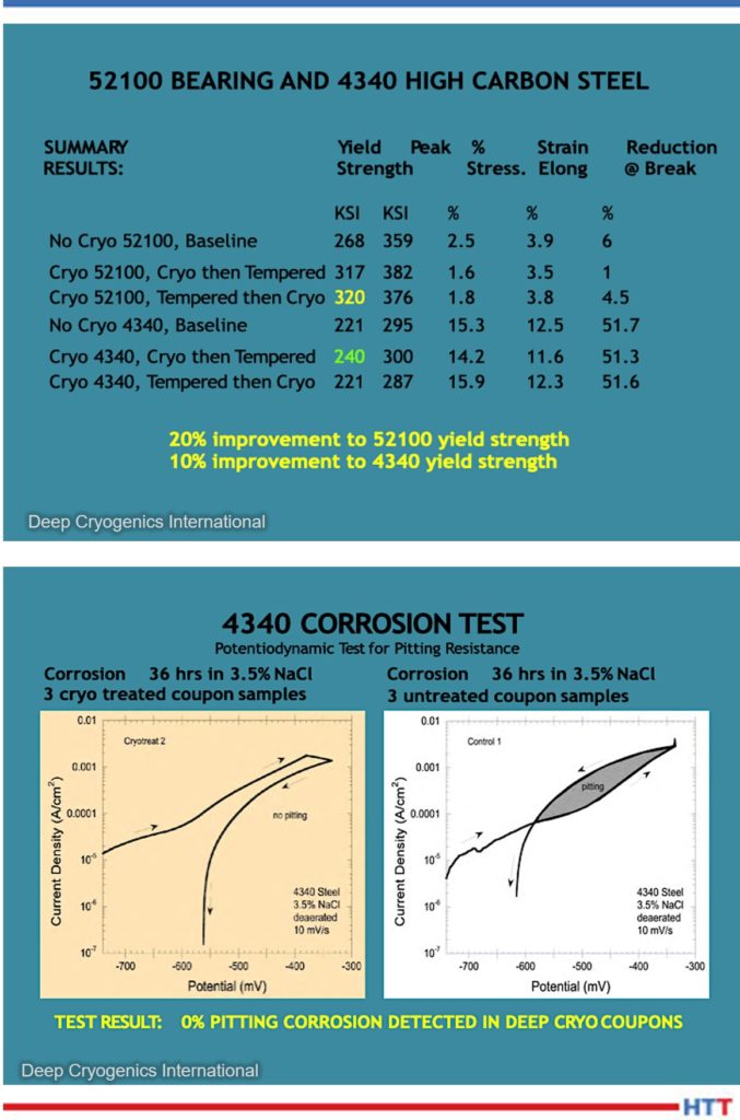

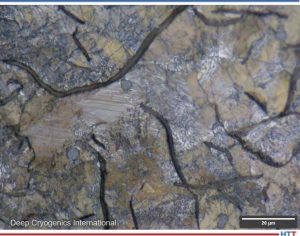
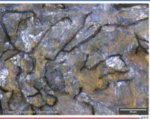
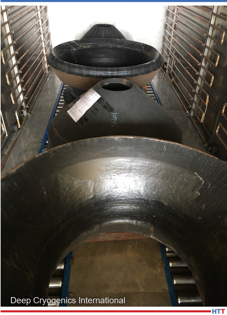
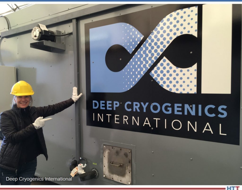
 Find heat treating products and services when you search on Heat Treat Buyers Guide.com


 DG: I should congratulate you on that degree, by the way. I know a year or so ago, you were still working on that, so that’s great!