Today’s tips come to us from AFC-Holcroft, covering Thermocouples, Atmospheres, and Flow Power.
Heat Treat Tip #4
Pack Your Thermocouples
When a thermocouple is used with an open-ended protection tube, pack rope or fiber between the thermocouple and the protection tube to prevent cold air infiltration from influencing the reading.
Photo Credit: Super Systems, Inc. (SSi)
Heat Treat Tip #7
A Good Fit
If a thermocouple fits loosely in a protection tube, avoid errors by ensuring that the tip maintains good contact with the tube.
Photo Credit: Super Systems, Inc. (SSi)
Heat Treat Tip #25
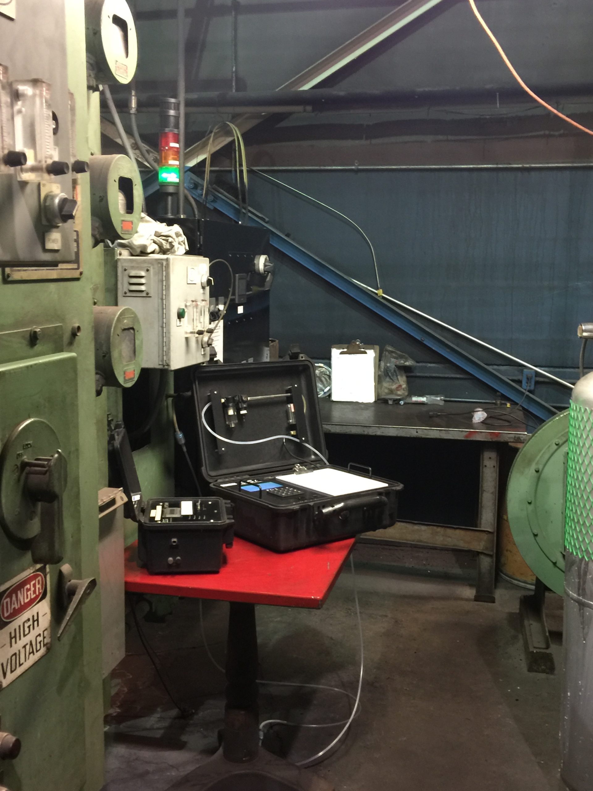
Oxygen Analysis as a Cost Saver
Investing in and using an oxygen analyzer on a regular basis can provide significant fuel cost savings and, at the same time, optimize uniformity and maximize capacity.
Photo Credit: Super Systems, Inc. (SSi)
Heat Treat Tip #26
Flow Power
Pressure varies as the square of the flow. This means that to double the flow, with all else being constant, pressure must increase by a factor of 4. Also, power increases as the cube of the flow. Doubling the flow produced by a fan or blower requires an 8-fold increase in horsepower.
Heat Treat Tip #77
Puzzling Polarity?
If unsure of the polarity of a type K thermocouple, remember that the negative (red) leg is magnetic; the positive (yellow) is not.
Heat Treat Tip #94
Copper as a Leak Check
If maintaining dew point is a problem, and it’s suspected that either an air or water leak is causing the problem, run a piece of copper through the furnace. Air will discolor the copper; water will not.
Heat Treat Tip #97
Optimum Dew Point
It is much easier to produce low dew point gas in a generator (within reason) than it is to lower the dew point after the atmosphere is in the furnace using enriching gas.
Here is what readers are saying about recent posts on Heat Treat Today. Submit your comments to editor@heattreattoday.com.
Jason Schulze has written numerous articles for HTT about AMS2750E. Check them out by searching “Jason Schulze” at www.heattreattoday.com
Jason Schulze, Conrad Kacsik
READER QUESTION: As per AMS2750E, what is the number of reuses for nonexpendable base metal thermocouples (N type MIMS TCS) above 980°C? Our application is TUS and SAT from 700°C to 1250°C. We would like to use N type MIMS thermocouples for both TUS and SAT. Recalibration period is specified as 3 months for N type thermocouples in AMS2750E. But no details are provided for the number of reuses above 650°C.
Jason Schulze (Conrad Kasik) for HTT: The number of permitted uses depends on the intended use of the thermocouple. For example, if the Type N thermocouples are used at 980°C (1796°F) as load thermocouple, the maximum permitted use would be 3 months or 180 uses, whichever comes first. If the thermocouple is used as a resident SAT thermocouple, it would need to be replaced every three months. In this case, the usage limit would be limited to 3 months. This will not be changing when the new version of AMS2750F is released.
We welcome your inquiries to and feedback on Heat Treat Today articles. Submit your questions/comments to editor@heattreattoday.com.
Dan Szynal, VP of Engineering and Technical Service, the Plibrico Company
A significant number of refractory lining failures can be traced to either faulty design or improper installation of the anchor system. The tips of anchors in particular need special consideration due to their exposure to the highest temperatures.
In this Technical Tuesday feature for Heat Treat Today, Dan Szynal, Vice President of Engineering and Technical Service for the Plibrico Company, a manufacturer of monolithic refractories, gives 3 important tips for refractory engineers and managers to use in achieving an improved anchor design.
It is estimated that up to 40% of refractory lining failures can be attributed to a problem with the design of the anchor system or improper installation. This is a significant number. When designing a refractory lining for an industrial application, anchor design becomes one of the most important factors in creating an improved lining that is supported properly. In particular, the tips of the anchors experience the highest temperatures because they are closest to the hot face and thus become an important consideration.
Anchors have several functions. They hold the refractory to the wall to keep it from falling in. They also prevent wall buckling due to the internal thermal stresses created by high temperatures. And, to a lesser degree, anchors can also help support the load of the refractory weight.
To create a monolithic refractory lining that is properly supported and maximizes service life, here are three important metallic anchor tips you need to know.
Anchor Types and Service Temperatures
Figure 1.0: Recommended anchor tip temperature limits for various common alloys
For refractory linings using metallic anchor systems, refractory engineers and designers almost always use Class III austenitic stainless-steel anchors of various qualities. The typical grades of stainless steel used are AISI 304, 309, and 310. These contain chromium and nickel to provide the best corrosion resistance and ductility at high temperatures. For some applications in which temperatures are more extreme and the use of ceramic tile anchors is not practical for various reasons, AISI 330 and even Inconel 601 is sometimes used. These anchors have higher nickel content for superior oxidation resistance and tensile strength at temperatures of 2000°F or higher. Inconel 601 gives the added advantage of good resistance to both carburization and sulfidation in extreme applications.
Industry Best Anchor Practices
Anchor sizing for a refractory lining depends on the refractory thickness and number of components. Some designers use the practice of sizing the anchor height to be 75-85% through the main dense castable or gunned lining. Other rules of thumb used in the industry dictate that the anchor tip should be no more than two inches from the hot face of the refractory for thicker lining designs greater than 6-7″.
For refractory applications, it is useful to know the temperature gradient through the refractory lining–from the hot face to the cold face–to choose the proper anchor size so that one doesn’t exceed the temperature limit of the alloy being used. To help calculate the correct temperatures at different points in the refractory lining, many industry professionals will use a heat loss calculator/estimator. By using a heat loss calculator/estimator, one can choose the proper anchor height by determining the anchor tip temperature it will experience. There are numerous heat loss applications that can estimate the cold face of a furnace lining given the input conditions of a thermal unit. As part of its value-added service as a refractory solutions provider, Plibrico Company, LLC, has a web-based heat loss application that gives a good estimation of the thermal gradient of the refractory lining from hot face to cold face to maximize anchor thermal performance.
For example, look at figure 2.0. You can see a 9″ side wall of refractory lining using 6″ of a typical 60% alumina low-cement castable and 3″ of 2300°F lightweight insulating castable for an application operating at 2000°F with an ambient temperature of 80°F. For this application, we would select 309 SS or 310 SS metallic anchors because the intermediate temperature at about 80% of the main lining thickness is at about 1900°F. Although 304 SS anchors would be more cost effective and are most commonly used in the industry, the anchor tips would oxidize at this temperature and would essentially burn out.
A Word on Anchor Tips
Standard practice for several years now has been to allow for expansion of the anchor tines by covering the anchor tips with plastic caps, dipping them in a wax, or putting tape on them. Metallic anchors expand at about three times the rate of alumino-silicate refractories. The expansion material affixed to the anchor tips burns out at low temperature and allows the anchor space to expand without causing cracks in the refractory.
Best practices in metallic anchor design also must include anchor spacing. Greatly a function of the specific equipment and geometry size, refractory engineers must consider the specific installation area. For example, anchor spacing patterns will be different in a flat wall or roof as compared to a section that has a transition of geometry or a less critical area of a vessel.
Anchor spacing should be based on the features of each specific project, such as mechanical properties of the anchor, and the refractory lining as a function of the temperature. Refractory engineers will use these properties in mathematical models to help create the optimal anchor spacing pattern and plan.
Often, failures commonly attributed to the refractory component can, in fact, be caused by deficiencies in the anchoring system. A strong anchoring system is key to maintaining monolithic refractory lining integrity, even when it is cracked, to prevent a total structural collapse.
To prevent vessel lining failures, increase service life, and maximize refractory performance, incorporate these metallic anchor tips. With these tips, it is possible to design and optimize an anchoring system that will work well with the demanding needs of refractory linings today.
For more information about metallic anchors and refractory anchoring systems, contact the Plibrico Company at contact@plibrico.com
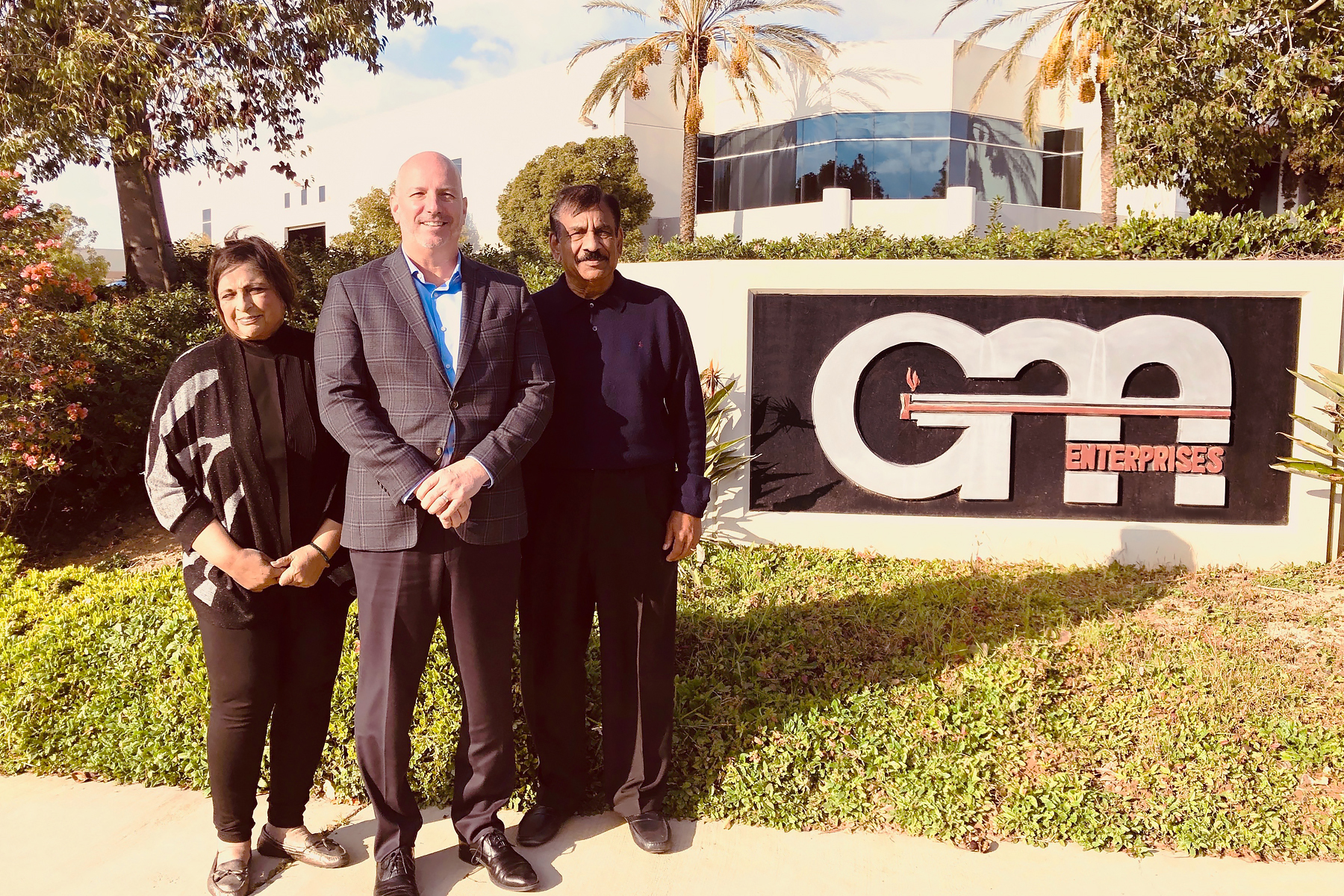
Nitrex, a global provider of fully integrated heat-treating solutions and technologies based in Montreal, Canada, acquired G-M Enterprises, a manufacturer of vacuum furnaces, headquartered in Corona, California.
Mrs. Veena Jhawar, G-M Enterprises COO; Mr. Jean-François Cloutier, Nitrex CEO; Mr. Suresh Jhawar, G-M Enterprises President
The addition of G-M Enterprises will further expand Nitrex’ integrated heat treatment solutions to customers; both share the same goal of providing technologies that focus on customer workflow and efficiency while maximizing the life span and quality of engineered parts and components.
Jean-Francois Cloutier, Nitrex CEO
“This acquisition will allow Nitrex to bolster its turnkey solutions business by bringing a new, innovative and broader mix of heat treatment systems to our customers,” said Jean-Francois Cloutier, Nitrex CEO. “We also look forward to welcoming the entire G-M Enterprises’ team into the Nitrex family.”
“Joining forces with Nitrex and becoming part of its family of companies will ensure we keep pace with our customers’ evolving needs and expectations,” says Suresh Jhawar, G-M Enterprises President. “What this means for the future of G-M Enterprises is an opportunity to enhance our products and services, expand our international presence further by leveraging the resources, expertise, and capital of Nitrex.”
A Polish immigrant, who worked hard to build a successful heat treating business, has achieved the dream he came to America to pursue.
When William Pociask emigrated to the U.S. from Poland, he learned English, attended Catholic schools and later Youngstown State University, then worked for a local tool and die company, delivering materials for heat treating to another tool and die firm in the area.
From that experience, he saw the need for an independent heat treating company where people could take their work rather than take it to a competitor. That spurred him to found P&L Heat Treating and Grinding Inc. 41 years ago. He owned the company until last year when he sold it to Thermal Process Holdings Inc. and is now its general manager.
The company started with heat treating aluminum extrusion dies, then moved into grinding, forging and stamping dies and parts for the railroad and mining industries. It now offers an array of heat treating, hardening, tempering and nitriding services.
“We do quite a bit for automotive,” Pociask says. Its customers include Ohio Star Forge, which produces parts for Japanese automakers, and suppliers to Ford and Dodge. The company produces dies for heavy-equipment manufacturers such as Caterpillar and International Harvester.
Pociask, who visited other Thermal plants before agreeing to the sale, says joining with the company gives P&L the ability to increase its expertise and to shop at better prices for the products it uses.
“A year later, I’m very proud that I did this. Their goals and their thoughts are just like mine,” he says. “They treat our employees very well and they value our customers, processes and so forth. [Thermal is] a very good organization that will take this business to the next level.”
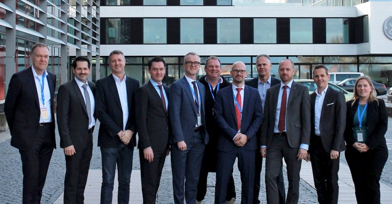
A global technology group, an industrial gases company, an additive and design company, and an engineering university in Germany have entered into a research partnership with the end goal of supporting the aerospace and automotive industries through their research and development of aluminum based-alloys.
Oerlikon, a global technology group, entered into a research partnership with Linde, an industrial gases company, GE Additive, an additive and design company, and the Technical University of Munich (TUM), a leading German university in engineering, to conduct additive manufacturing (AM) research with the aim of developing new high-strength, lightweight aluminum-based alloys that can serve the safety and weight reduction needs of the aerospace and automotive industries.
Dr. Marcus Giglmaier, Project Manager for the AM Institute
This collaboration seeks to address the challenge of aluminum AM. “There are significant challenges during the AM of aluminum alloys because the temperatures reached in the melt pool create an extreme environment that leads to evaporation losses of alloying elements that have comparatively low boiling temperatures — such as magnesium,” said Dr. Marcus Giglmaier, project manager for the Additive Manufacturing Institute and research funding manager. “Additionally, the cooling rates of more than 1 million °C per second, create high stresses during the solidification process, which can cause micro cracks in the solid material.”
The project draws on the strengths of each of its members. Oerlikon’s experience in powder and material science will contribute to the development of the novel material; Linde’s technology and expertise in gas atmosphere control and evaporation suppression during the AM process – including the processing of aluminum-based alloys – overcomes impurities within the print chamber, which will help manufacturers achieve optimal 3D-printing conditions; GE Additive will assist in the collaboration; and, for its part, the Institute of Aerodynamics and Fluid Mechanics (AER) at TUM will be able to provide a detailed understanding of the physical phenomena taking place during the AM process using numerical simulations.
From left to right: Dr Sven Hicken (Business Unit Head, Oerlikon AM), Prof Thomas Hofmann (President, TUM), Jason Oliver (President and CEO, GE Additive), Dr Wolfgang Dierker (CEO, GE Germany), Dr Christoph Laumen (Executive Director R&D, Linde AG), Prof Michael Suess (Chairman of the Board of Directors, Oerlikon Group), Dr Christian Haecker (Head of Industrialisation, Oerlikon AM), Dr Andreas Lessmann (Managing Director, GE Additive Germany GmbH, Senior Leader, Legal Operations), Dr Christian Bruch (Executive Vice President & CEO, Linde Engineering), Andreas Rohregger (Head of Global Properties, GE Additive), Dr Alice Beck (Deputy Director, TUM ForTe) (Courtesy Oerlikon)
A global materials engineering group explored alternative methods of applying a hard surfacing alloy at the ITSC conference in Japan.
Engineers from Wall Colmonoy Corp. discussed in a conference presentation how the properties of a hard surfacing alloy change when applied by different methods. Alloy Ni-15Cr-15W-3B-4Si-3.5Fe-0.6C is a hard surfacing alloy designed to extend the life of OEM parts that are subjected to various wear mechanisms in service. The alloy can also be used to repair/rebuild those worn parts and extend service life.
This hard-surfacing alloy can be applied by various methods, including thermal spray processes, laser cladding, PTA welding, GTAW, OFW, and GMAW. This study compared the properties of the alloy applied by different methods using various test procedures, and also included the cost/benefit ratio of each.
Test procedures included abrasion testing by ASTM G-65; erosion testing by ASTM G-76; Vickers hardness by ASTM E-92; and Rockwell hardness by ASTM E18. In addition, metallographic examples of the test specimens were prepared.
A steel producer based in Fort Wayne, Indiana, recently announced the expansion of their rolling mill, which will include a 3-MW induction furnace to heat the stock coming from the existing mill.
Steel Dynamics USA announced the expansion at their Columbia City, Indiana, location. Among other equipment being added are a 70-m conveyor connecting the existing medium section mill to the new spooler line, six housingless SHS 180 roller stands, complete with quick stand-changing table, a 6-pass Delta-type finishing block driven by a low-voltage- 2.5-MW motor and finishing services.
SDI and Danieli teams studied a temporary removable solution, steel support structure to support the existing furnace-exit roller table, allowing the execution of the Billet Welder concrete foundation with only minor impact to the MSM (Medium Section Mill) production schedule.
A western Pennsylvania heat treat provider recently completed construction of a new brazing and assembly room, built primarily to accommodate a large aluminum brazing project for a specific customer.
Bob Hill, president of Solar Atmospheres of Western PA
Solar Atmospheres of Western PA, based in Hermitage, Pennsylvania, stated that the room will also be used for other brazing and assembly work.
“During successful development and prototype runs, our customer, along with Solar management, understood that in order to bring this critical aluminum brazing project to full production a separate braze/assembly room would be needed,” said Bob Hill, president of Solar Atmospheres of Western PA. “We worked together with our customer to develop the best space that is in close proximity to the vacuum furnace being utilized.”
Main photo credit/caption: Solar Atmospheres / The inspection of critical braze joints being analyzed within Solar’s newly constructed Braze-Assembly room.
This article continues the ongoing discussion on Equipment Selection for Induction Hardening by Dr. Valery Rudnev, FASM, IFHTSE Fellow. Six previous installments in Dr. Rudnev’s series on equipment selection addressed selected aspects of scan hardening and continuous/progressive hardening systems. This post is the third in a discussion on equipment selection for one of four popular induction hardening techniques focusing on single-shot hardening systems.
Previous articles in the series on equipment selection for single-shot hardening are here (part 1) and here (part 2). To see the earlier articles in the Induction Hardening series at Heat TreatToday as well as other news about Dr. Rudnev, click here.
Single-Shot Inductors for Non-Cylinder Parts
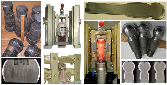
Single-shot inductors can be successfully used for hardening not only components of classical cylinder geometries but other geometries as well. This includes workpieces of general conical shapes, such as elliptic, parabolic, hyperbolic geometries—and the list can grow. As an example, Figure 1 shows induction surface-hardened ball joints (ball studs) and the single-shot inductors used to harden them. Ball studs are used in automotive, off-road, and agricultural machinery and can be different in shape and size (Compare images on the left in Figure 1 with images on the right.), requiring noticeably different hardness patterns.
Figure 1. Surface-hardened ball joints (ball studs) and single-shot inductors used for its hardening. (Courtesy of Inductoheat Inc., an Inductotherm Group company.)
In any attempt to scan harden workpieces with appreciable diameter changes, the scan coil must have a sufficient gap to clear the largest diameter. When scanning the section(s) of the workpiece with smaller diameters, an inductor-to-shaft air gap might be very large, resulting in low electrical efficiency and potentially exhibiting difficulties in load matching as well as in controlling the austenitizing pattern along the length of the part producing "cold" and "hot" spots. Additional difficulties may appear in controlling the hardness pattern in regions (e.g., near geometrical irregularities) where good control is most needed.
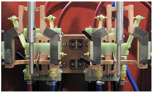
Thus, the substantially different workpiece-to-inductor electromagnetic coupling variations might not permit using classical multiturn solenoid coils or scan inductors. In contrast, single-shot inductors allow not only better electromagnetic coupling along the entire length of heat treated components (Figure 2) but also better address the geometrical irregularities of heat treated workpieces, producing the required hardness patterns at minimum process times with superior metallurgical quality.
Figure 2. Single-shot inductors allow better electromagnetic coupling along the length of heat treated components properly addressing the geometrical complexity of the workpiece. (Courtesy of Inductoheat Inc., an Inductotherm Group company.)
As stated in Part 1 of this series, in contrast to scan hardening, a single-shot inductor can be contoured along the length of the part properly addressing the geometrical complexity of the workpiece. Furthermore, the use of flux concentrators helps drive the current into the desired areas and allows producing a well-defined hardness profile with minimum distortion. The trade-off here is that more finesse is required in the design stage to produce the properly profiled single-shot inductor at the lowest possible cost.¹ Errors are costly since these inductors are each custom made for a given part or application and modifications can be quite costly. Thus, computer modeling is a helpful assistant as an attempt to keep the development cost down and shorten the "learning curve".
Proper hardening of such components as output shafts, flanged shafts, planet carriers, yoke shafts, sun shafts, intermediate shafts, driveshafts, turbine shafts, and some others may require extensive copper profiling, making a single-shot hardening inductor a complex electromagnetic device.
Certain geometrical features such as flanges, diameter changes, bearing shoulders, grooves, undercuts, splines, etc., may distort the magnetic field generated by an inductor, which, in turn, can cause temperature deviations, making it challenging to achieve certain hardness patterns.
For components containing fillets, it is often necessary to increase the heat intensity in the fillet region owing to the geometrical specifics. Also, the larger mass of metal in the proximity of the heated fillet and behind the region to be hardened produces a substantial thermal “cold sink” effect.¹ This draws heat from the fillet due to thermal conduction, which must be compensated for by generating additional heating energy in the fillet area.
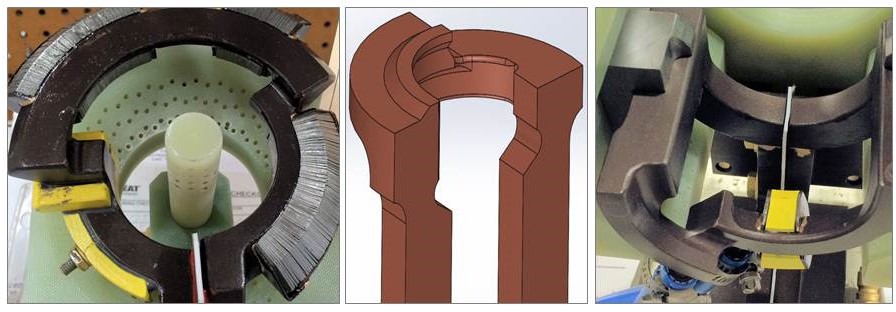
Needed energy surplus can be achieved by narrowing the current-carrying face of the crossover segment of the single-shot inductor (Figure 3). Here is a simplified illustration of an impact of a copper profiling of the inductor’s heating face: if the current-carrying portion of the inductor heating face is reduced by 50 percent, there is a corresponding increase in current density. This will be accompanied by an increase of the eddy current density induced within the respective region. According to the Joule effect, doubling the induced eddy current density increases the induced power density roughly by a factor of four. Also, attaching a magnetic flux concentrator to certain areas of the hardening inductor further enhances the localized heat intensity.
Figure 3. Longitudinal leg sections of single-shot indicators and their crossover segments can be profiled by relieving selected regions of the copper to accommodate workpiece geometrical features. Attaching a magnetic flux concentrator to certain areas of the inductor further enhances localized heat intensity. (From V. Rudnev, A. Goodwin, S. Fillip, W. West, J. Schwab, S. St. Pierre, Keys to long-lasting hardening inductors: Experience, materials, and precision, Adv. Mater. Processes, October 2015, pp. 48–52.)
When using a single-shot inductor, it is particularly important that the workpiece is properly located in the heating position because seemingly minor dislocations may noticeably affect the heat treat pattern and metallurgical quality of hardened parts.
Traditionally designed single-shot inductors may exhibit high process sensitivity that is associated with the electromagnetic proximity effect.¹ A change in positioning of the workpiece inside the single-shot inductor attributed to excessive bearing wear of the centers, improper machining of the centers and fixtures, incorrect part loading, and other factors may produce a correspondent appreciable variation in the hardness pattern (particularly within the fillet region, undercut areas, and the part’s end zone). A reduced hardness case depth and the formation of unwanted microstructural products associated with incomplete phase transformation may be the result of that. Magnitude and distribution of transient and residual stresses might also be altered. Thus, attention should be paid to part’s reliable positioning during heating and quenching cycles.
As can be concluded, there are good reasons for using single-shot hardening, scan hardening, or continuous/progressing hardening approaches in induction hardening applications. The decision must be well thought out based on many factors such as geometry specifics, product quality, production rate, design proficiency, limitations of available equipment, reliability requirements, cost considerations, and some other factors.
The next installment of this series, “Dr. Valery Rudnev on . . . ”, will continue the discussion on design features of induction single-shot hardening systems.


 industry’s foremost experts.
 Pack Your Thermocouples
 A Good Fit
 Oxygen Analysis as a Cost Saver
 Optimum Dew Point