MANUFACTURING HEAT TREAT

This Week in Heat Treat Social Media


Welcome to Heat Treat Today’s This Week in Heat Treat Social MediaAs you know, there is so much content available on the web that it’s next to impossible to sift through all of the articles and posts that flood our inboxes and notifications on a daily basis. So, Heat Treat Today is here to bring you the latest in compelling, inspiring, and entertaining heat treat news from the different social media venues that you’ve just got to see and read!

Check out today’s line-up of Halloween Costumes, Thanksgiving and your heat treat furnace, a video on the details of stress relieving, and more!

If you have content that everyone has to see, please send the link to editor@heattreattoday.com.


1. Get Ready for Thanksgiving

Typically, we like to start these posts with an intriguing or exciting metallurgical post from the industry. But with Thanksgiving right around the corner, we know you would like to contribute with the skills that you use every. Single. Day. Still, be careful… Enjoy this video from Ipsen USA.


2. Technically Know How

We see you! And we think it’s awesome! Here are several videos and images of heat treat techniques and shared knowledge. Feel free to @HeatTreatToday when you post these videos so that we can see them!

.

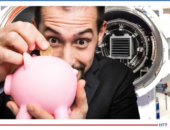
In-House Heat Treating Looking Pink

.

Standing Ovation for Your Traditional Flames

.

A Series in a Heat Treater’s “Expedition”

Check out their video here!

.

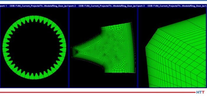
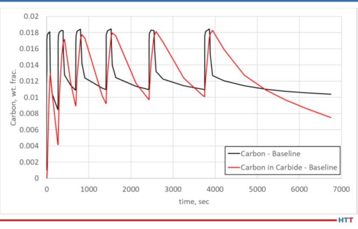
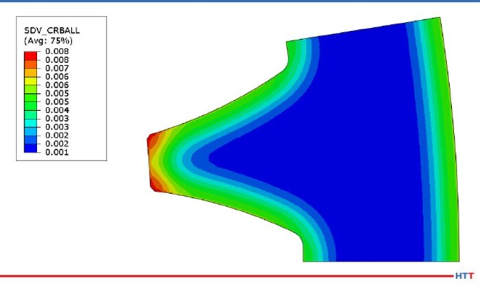
Carbon Content and Heat Treatment

.


3. Historical Heat Treat

Talk about throwbacks, these videos and images from the “social-inter-webs” share some interesting factoids and knowledge from the past. Check out heat treating video from the 1970s, heat treatment in Japanese culture, and 6,500 year-old copper workshop.

.

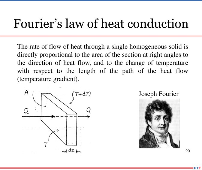
1973 – Properties and Grain Structure Video

Check out this video, “Properties and Grain Structure: BBC 1973 Engineering Craft Studies,” and let us know if you agree with one of the commenters: “Please never remove this video from youtube. This video is a majestic gem in an ocean of gray pebbles.” If you share it on your LinkedIn page, @HeatTreatToday so we know what you think!

.

The Art of Mokume Gane

Full disclosure: this is NOT at the high temps that you are used to. But still…get a load of Mokume Gane: “it is an ancient Japanese technique used to make jewelry, blade guards and many other things. It is basically Damascus or pattern welded steel, but made from non ferrous metals such as gold, silver, copper, brass, platinum, bronze etc.” (Source: HomemadeTools.Net)

.

Secrets of the Desert 

Tel Aviv University and Israel Antiquities Authority believe copper-producing technology was closely guarded secret in the Neveh Noy neighborhood of Beer Sheva, capital of the Negev Desert. This emergency archeological excavation came about to safeguard threatened antiquities. Now, “The new study also shows that the site may have made the first use in the world of a revolutionary apparatus: the furnace.” (Source: Tel Aviv University: American Friends)

Work on the dig in Beer Sheva. Photograph credit: Anat Rasiuk, Israel Antiquities Authority.
(Source: “6,500-year-old copper workshop uncovered in the Negev Desert’s Beer Sheva,” Tel Aviv University: American Friends)


4. Reading and Podcast Corner

Free Classes Anyone? Thank you, C3 Data

.

Heat Treat Radio: Rethinking Heat Treating (Part 3 of 4) — The Fracking Pump Valve Seat

The latest episode is with integrated heat treating professional Joe Powell and Doug Glenn as they talk about the fascinating heat treatment of a fracking pump valve seat.


.

Heat Treat Radio: Andrew Bassett on AMS2750F (Part 2 of 3) — SATs

Get ready for the next episode in this series being released in early December with this podcast! Doug Glenn continues his conversation with AMS2750F expert Andrew Bassett. This time, the pair discusses Revision F changes to System Accuracy Tests (SATs).


.

Heat Treat Radio: Rethinking Heat Treating (Part 2 of 4) — 18″ Bevel Gear

Savings of over $700.00 in hard grinding costs PER GEAR on an 18-inch bevel gear? Listen to  Joe Powell of Integrated Heat Treating Solutions tell how they did it. [Go to Heat Treat Radio with Joe].

[blockquote author=”Joe Powell” style=”1″]“It’s a win-win-win.  The customer is happy, we’re happy and it works.  This demonstrates that you can indeed quench very, very intensively.  We’re talking about 400-600 degrees Centigrade/second of quenching.”[/blockquote]


5. Scary Manufacturing…Maybe

While this is not exactly metal, could any of you make this? Or maybe the more important question is, would any of you make this?


Have a great weekend!


This Week in Heat Treat Social Media Read More »

Predictive Maintenance and Saving Money

Source: TAV-The Vacuum Furnace Blog

We hear the term “preventative maintenance” often used in the industry. Setting up procedures in advance to avoid unplanned downtime and other avoidable costs is certainly a hot topic. But this Heat Treat Today Best of the Web feature highlights a maintenance strategy that has become increasingly popular in creating better industrial efficiency: predictive maintenance. Read today’s feature article to learn about what predictive maintenance is, how it is implemented in a vacuum furnace system, and how this strategy saves you money.

An excerpt: “Predictive maintenance (PdM) evaluates the condition of equipment by performing periodic or on-line asset condition monitoring. Most PdM is performed while vacuum furnace is operating normally to minimize disruption of everyday operations. This maintenance strategy leverages the principles of statistical process control.”

Read more: “Save Time and Money with Vacuum Furnace Maintenance [2/2]


(Source: TAV Vacuum Furnace Blog)


Predictive Maintenance and Saving Money Read More »

What to Expect When Remodeling a Kiln Control System

OC

jose sanchez
José P. Sanchez
Ceramics Business Unit
Nutec Bickley

Heat Treat Today brings you an article from Jose Pablo Sanchez at Nutec Bickley on what to expect when giving a kiln or furnace an upgrade.

How much time does it take to replace or upgrade your heat treat kiln or furnace? What are the best questions to ask when preparing to upgrade a control system on your furnace or kiln? What about the availability of replacement parts? How can you be sure that your upgrade will deliver the overall best experience once it is said and done? Read on to consider the case study of one client’s experience when remodeling a kiln control system.


About the Client

One of the most renowned sanitaryware manufacturers in the world wanted to update the control system on one of their older tunnel kilns. The 30–40 year-old equipment had an outdated control system which ended up leading to a lengthy installation process

Since the kiln’s control system was obsolete, the client could not access the controller’s program, making any required modification impossible. Additionally, the kiln did not have a HMI screen, only a board with LEDs. The SCADA system was DOS based, very unfriendly and difficult to operate. This made sourcing any necessary replacement parts extremely difficult in the event of failure.

The Challenge

The client had been forced to search for spare parts on eBay and other online sites as they had been discontinued by the part manufacturer. But even with these searches, it had become impossible to find replacement parts.

Tunnel kilns handle a substantial throughput and are generally only idle when they are closed down for a week at the end of the year for maintenance.

So, the challenge that the client and our engineers faced was to uninstall the current system, install the new one, and get everything ready, all before the plant resumed operations.

To this end, we worked 24 hours a day continuously, conducting tests during the final week of the year with our team of programmers and commissioning engineers.

Equipment Supplied and Technology Employed

Installation of new SCADA and PLC equipment

1.- Allen-Bradley ControlLogix® PLC

  • A high-performing PLC
  • Improved processing power

2.- New SCADA from FactoryTalk®

  • Replaced the obsolete system the client was using
  • More programming versatility on screens

The Solution

In updating the system, we proposed replacing the old controller with an Allen-Bradley ControlLogix® PLC and installed a new FactoryTalk® SCADA for screen control. These updates took time both prior to installation and during the installation itself.

First, the existing program could not be accessed, so multiple visits to the client’s factory were necessary to study the kiln’s operation philosophy. Second, since the control panel wiring had no labels, we took time to label every component and ensure that the wirings corresponded to the correct signals. Additionally, we brought in a commissioning engineer who checked the functionality of the instrumentation before any intervention.

When it came to installation, a systematic process was essential. Every time a component was connected it was tested immediately. We had up to 5 automation engineers at a time for quick troubleshooting.

Results Obtained

A key part of the process was the client’s cooperation. They always had someone there with us to help us with anything we needed. With our engineers, the facility was able to obtain:

  1. The latest hardware and software systems
  2. Technical support and easy refurbishment capabilities
  3. The ability to add more cards in the future to improve monitoring
  4. Increased flexibility to customize systems
  5. Better monitoring and data analysis of kiln performance results
  6. Remote access from the Nutec Bickley plant for testing and troubleshooting purposes


This proves that the client’s cooperation is always key for a successful project.


Images provided by Nutec Bickley.

About the Author: José P. Sanchez is part of the Ceramics Business Unit in Nutec Bickley, in charge of sales in LATAM for kilns and major retrofits in the ceramic industry. He has been an active participant of multiple projects involving kilns and ovens in numerous industrial sectors, mostly refractories for the steel & aluminum industry.


What to Expect When Remodeling a Kiln Control System Read More »

Case Study: The Low-Pressure Carburizing Process Improvement for a Ring Gear

Justin Sims
Lead Engineer
DANTE Solutions

OC“The original LPC schedule, consisting of six boost-diffuse steps, was producing large amounts of carbides during the process. With large amounts of primary carbides in the case of the heat treated gear, rolling contact fatigue performance was decreased.”

Heat Treat Today‘s Technical Tuesday feature, “Low Pressure Carburizing Process Improvement for a Ring Gear: Controlling Carbide Formation during LPC,” explores a case study, written by Justin Sims, lead engineer at DANTE Solutions, about how software modeling aids heat treaters in improving their low pressure carburizing process. Enjoy today’s Original Content.


Introduction

Low pressure carburizing (LPC) processes are becoming more widespread throughout industry due to the reduced cycle times and the control over the carbon profile through the case. Unlike gas carburizing, which utilizes a constant carbon potential to maintain the available carbon on the part surface at a specific value, LPC utilizes a series of boost and diffuse steps. A boost step involves the temporary addition of a carbon carrying gas to the furnace chamber, usually acetylene, to increase the surface carbon to the saturation limit of austenite. If not properly controlled, the carburized case may have an excessive amount of carbon, which damages the final microstructure. After a requisite amount of boost time, generally half minute to several minutes, the carbon carrying gas is evacuated from the chamber. The concentrated carbon in the shallow surface layer from the boost step is then allowed to diffuse into the part, reducing the surface carbon. These two steps are then repeated until the required case depth and carbon profile are achieved.

For steel alloys that do not contain a significant amount of strong carbide forming elements, the LPC process is relatively easy to control. However, with the advent of high strength steels for the aerospace industry, most of which contain substantial amounts of strong carbide forming elements, such as chromium, molybdenum, and vanadium, the LPC process can be challenging. The primary carbides formed during the LPC process, if not properly dissolved, can damage fatigue performance.

While Fick’s Second Law describes the diffusion of carbon through a low alloy steel with reasonable accuracy, the same is not true of medium and high alloy steels. This is due to the presence of carbides forming and dissolving during the LPC process. During a boost step, the carbides formed increase the total amount of carbon into the surface. During the diffuse step, as the carbon that is in solid solution diffuses into the part, reducing the carbon in austenite, the carbides can dissolve to provide more carbon to the solid-state solution. If the carbides are not allowed to fully dissolve or shrink to a significantly small size before the next boost step begins, they will continue to grow. In order to properly predict the carbon profile of medium and high alloy steels, the carbide formation and dissolution must be considered. The heat treatment simulation software DANTE has implemented this feature.

The following is a case study for redesigning a LPC schedule of a ring gear using DANTE. The original LPC schedule, consisting of six boost-diffuse steps, was producing large amounts of carbides during the process. With large amounts of primary carbides in the case of the heat treated gear, rolling contact fatigue performance was decreased.

Image 1

Geometry and Model

Part: Ring Gear

  • Material: Ferrium C64
  • Outer Diameter: 5.5 inches
  • Inner Diameter: 4.5 inches
  • Height: 0.060 inches
  • Number of Teeth: 40

Model: Single Tooth

  • Cyclic Symmetry: Carbon boundary conditions
    act uniformly on all teeth
  • Number of Elements: 233,850 linear hexagonal
  • Number of Nodes: 245,055
  • Higher mesh density near surface to capture
    steep carbon gradients


LPC Experiments vs. Prediction

Image 2
  • Experimental data versus DANTE prediction for 3 LPC runs
  • LPC experiments conducted using a cylinder with a 4-inch OD and a 4-inch height made of Ferrium C64
  • 3 different boost-diffuse schedules executed
    • 6 boost-diffuse steps
    • All 3 schedules used the same first 11 steps
    • Final diffuse time increased for each run, with Run 1 having the shortest and Run 3 having the longest
  • LECO used to measure the carbon profile of the test coupons
  • DANTE model parameters for carbon diffusivity, carbide formation, and carbide dissolution fit from experimental data
    • Simulation matches experimental data reasonably well


Baseline (Original Carburizing Process)  Model Results

  • The case depth originally was designed for 0.75 mm (0.030 inch) on the flank of the tooth, with a carbon value of 0.3% resulting in a hardness value of 50 HRC for Ferrium C64 when tempered at 495°C (925°F).
  • The contour plot shows all carbon, the carbon in the austenite matrix and the carbon in primary carbide form, at the end of the process for the baseline model:
    • Areas above 0.011 carbon contain primary carbides
    • Tip contains a high amount of primary carbides
  • Line plot shows the predicted carbon in the austenite matrix (Carbon) and the carbon in primary carbide form (Carbon in Carbides) at the surface of the flank for the baseline model over the total time of the process.
    • Carbides present at a depth of 0.25 mm (0.010 inch)
    • Case depth ~0.35 mm deeper than required
Image 3
Image 4


  • Contour plot shows all carbon, the carbon in the austenite matrix and the carbon in primary carbide form, at the end of the 3rd boost and diffuse steps
  • Line plot shows the predicted carbon in the austenite matrix (Carbon) and the carbon in primary carbide form (Carbon in Carbides) at the surface of the flank for the baseline model over the total time of the process
    • Carbides formed during the first boost step continue to grow as the process progresses, indicated by the increasing carbon in carbide
    • Final diffuse not long enough to fully dissolve carbides
Image 5
Image 6

Image 7

Redesigned Carburizing Process Model Results

Image 8
  • To ensure the primary carbides dissolve completely before hardening, a new schedule was developed with the aim of reducing the carbon in primary carbide form:
    1. 3 boost-diffuse steps were removed, and the diffuse times increased substantially.
    2. An increase in diffuse time increased the schedule by approximately one-half hour, which is acceptable given the positive results.
  • The contour plot shows all carbon, the carbon in the austenite matrix, and the carbon in primary carbide form at the end of the process for the redesigned process model.
  • Line plot shows the carbon in the austenite matrix (Carbon) and the carbon in primary carbide form (Carbon in Carbide) from the surface of the flank towards the core for the redesigned model at the end of the process
  • Small carbides (negligible) at a depth of 0.1 mm (0.004 inch)
Image 9
  • Easily removed with finish grinding operation
  • Contour plot shows all carbon, the carbon in the austenite matrix and the carbon in primary carbide form, at the end of the 2nd boost and diffuse steps for the redesigned process
    • Primary carbides are nearly fully dissolved, even in the tip (carbon is higher, but it is not in carbide form), at the end of the diffuse step
Image 10
Image 11


  • Line plot shows the predicted carbon in the austenite matrix (Carbon) and the carbon in primary carbide form (Carbon in Carbides) at the surface of the flank for the redesigned model over the total time of the process
    • Carbides are nearly fully dissolved after each diffuse step


Image 12

Summary

  1. The heat treatment simulation software DANTE model parameters for carbon diffusivity, carbide formation, and carbide dissociation fit from experimental data.
    • Any steel alloy and LPC equipment can be fit to the DANTE carburizing model.
  2. The software successfully predicted the results of a low-pressure carburizing process that was resulting in poor part performance during rolling contact fatigue:
    • Model showed that large primary carbides exist at a depth of 0.25 mm (0.010 inch).
    • Model showed that the carbides do not have time to dissolve during the boost steps.
  3. The software was used to successfully redesign the boost-diffuse schedule to improve rolling contact fatigue performance:
    • Model showed that small primary carbides (negligible) exist at a depth of 0.1 mm (0.004 inch).
    • Model showed that the carbides nearly fully dissolve during the diffuse steps.
    • Small carbides were removed during the finish grinding operation.
    • Rolling contact fatigue performance improved due to the absence of primary carbides near the surface.
  4. Additionally, the software is not limited to Ferrium C64 with respect to primary carbide formation during LPC:
    • Continually updating the material database with carbide behavior for different alloys
    • Continually validating the model with experiments


About the Author: Justin Sims is a lead engineer at DANTE Solutions. For more information, contact Justin at DANTE Solutions

All images were provided by DANTE Solutions.


Case Study: The Low-Pressure Carburizing Process Improvement for a Ring Gear Read More »

Heat Treatment of a Large H13 Liner is a Success

HTD Size-PR Logo

Bob Hill
President
Solar Atmospheres of Western PA

Lake Park Tool and Machine, located in Youngstown Ohio, produced a massive H13 liner which Solar Atmospheres of Western PA (SAWPA)recently heat treated. The liner measured over 100” OAL and weighed a total of 16,000 pounds. The liner was turned on Lake Park’s new large capacity lathe with 34” max diameter and 200” max length.

This H13 liner was heat treated in, what SAWPA says is, "the fastest cooling large vacuum furnace in the industry." Solar Manufacturing, sister company to SAWPA, recently completed this 10 bar vacuum furnace several months ago. It is equipped with a hot zone measuring 48” wide x 108” OAL. Additionally, the furnace has a 600 HP blower motor for increased cooling power. The critical cooling rate, to obtain optimum properties for H13 hot worked tool steel, was achieved in the as-quenched hardness of HRC 54-55. The part was then double tempered to the customer’s specification of HRC 46 to 48.

"This large rapid cooling vacuum furnace provides us continued diversification to our vacuum heat treating repertoire and capabilities. We’re proud of this partnership with Lake Park Tool and Machine and to assist our customers in vacuum heat treating one of the largest air hardening dies that I have personally heat treated over my 40 year career,” stated Bob Hill, president of Solar Atmospheres.


(photo source: Solar Atmospheres)


Heat Treatment of a Large H13 Liner is a Success Read More »

Heat Treat Tips: Brazing, Money Flow, and Quench Maintenance

One of the great benefits of a community of heat treaters is the opportunity to challenge old habits and look at new ways of doing things. Heat Treat Today’s 101 Heat Treat Tips is another opportunity to learn the tips, tricks, and hacks from some of the industry’s foremost experts.

Heat Treat Today’s latest round of 101 Heat Treat Tips is featured in Heat Treat Today fall issue (also featuring the popular 40 Under 40).

Today’s selection includes tips from ECM USA, Carrasco Hornos, and Quaker Houghton. Each of them has provided quick steps or comments on a variety of topics ranging from furnace brazing to furnace expenses to quench performance or maintenance.


Heat Treat Tip #1

How to Achieve a Good Braze

In vacuum brazing, be certain the faying surfaces are clean, close and parallel. This ensures the capillary action needed for a good braze.

Heat Treat Furnace
(Source: Ichudov at Wikipedia Commons)

A good brazing filler metal should:
1. Be able to wet and make a strong bond on the base metal on which it’s to be applied.
2. Have suitable melt and flow capabilities to permit the necessary capillary action.
3. Have a well-blended stable chemistry, with minimal separation in the liquid state.
4. Produce a good braze joint to meet the strength and corrosion requirements.
5. Depending on the requirements, be able to produce or avoid base metal filler metal interactions.

(ECM USA)


Heat Treat Tip #2

How Much Lost Money Flows Through the Walls of Your Furnace

In a strict sense, heat flows through the insulating lining of your furnace wall: the lower the outside temperature in the furnace shell, the less heat is lost and, consequently, less money.

Fourier’s Law of Heaat Conduction (Source: Carrasco Hornos)

For example, an outside temperature on the oven shell of 160°F (71°C) equals a heat loss of approximately 190 BTU/hr ft2, just multiply this number by the square footage of the entire outside surface of the oven. A well-designed and well-maintained insulation can reduce the outside temperature of the shell, say 120°F (49°C), and heat losses would be close to 100 BTU/hr ft2, that’s 90% more heat lost and therefore fuel.

So, my Tip for today is: “Let’s go for the basics that don’t change, and it will always give good results.” By the way, how many furnaces are there in your plant and how many square feet do their surfaces add up to?

(Carrasco Hornos)


Heat Treat Tip #4

Check Your Quench Oil

Safety – Performance – Oxidation

Safety

  • Water content should not exceed a maximum of 0.1% in the quench oil.
  • Flash point should be checked to ensure no extraneous contamination of a low flash point material (i.e. kerosene) has been introduced into the quench tank.

Performance

  • Cooling curve analysis or GM Quenchometer Speed should be checked to confirm the quench oil is maintaining its heat extraction capabilities. Variances in heat extraction capabilities could possibly lead to insufficient metallurgical properties.

Oxidation

  • TAN (total acid number) and Precipitation Number should be checked to ensure the quench oil is thermally and oxidatively stable. Oxidation of the quench oil can lead to staining of parts and possible changes in the heat extraction capabilities.
  • Sludge content should be checked… filter, filter, filter… sludge at the bottom of the quench tank can act a precursors for premature oxidation of the quench oil.

Work with your quench oil supplier on a proactive maintenance program… keep it cool… keep it clean… keep it free of contamination to extend the life of your quench oil.

(Quaker Houghton)


Heat Treat Tip #28

Aqueous Quenchant Selection Tips

Greenlight Unit
(Source: Quaker Houghton)

  1. Determine your quench: Induction or Immersion? Different aqueous quenchants will provide either faster or slower cooling depending upon induction or immersion quenching applications. It is important to select the proper quenchant to meet required metallurgical properties for the application.
  2. Part material: Chemistry and hardenability are important for the critical cooling rate for the application.
  3. Part material: Minimum and maximum section thickness is required to select the proper aqueous quenchant and concentration.
  4. Select the correct aqueous quenchant for the application as there are different chemistries. Choosing the correct aqueous quenchant will provide the required metallurgical properties.
  5. Review selected aqueous quenchant for physical characteristics and cooling curve data at respective concentrations.
  6. Filtration is important for aqueous quenchants to keep the solution as clean as possible.
  7. Check concentration of aqueous quenchant via kinematic viscosity, refractometer, or Greenlight Unit. [See image: Hougton Intn’l Greenlight Unit and/or Houghton Int’l GL Display B] Concentration should be monitored on a regular basis to ensure the quenchant’s heat extraction capabilities.
  8. Check for contamination (hydraulic oil, etc) which can have an adverse effect on the products cooling curves and possibly affect metallurgical properties.
  9. Check pH to ensure proper corrosion protection on parts and equipment.
  10. Check microbiologicals which can foul the aqueous quenchant causing unpleasant odors in the quench tank and working environment. If necessary utilize a biostable aqueous quenchant.
  11. Implement a proactive maintenance program from your supplier.

(Quaker Houghton)


Heat Treat Tips: Brazing, Money Flow, and Quench Maintenance Read More »

Mint of Poland Purchases Vacuum Heat Treat Furnace

HTD Size-PR LogoThe Mint of Poland, a producer of circulation and collector coins for the National Bank of Poland, has purchased a second vacuum furnace from an international heat treat supplier. The historic 250 year-old-plus institution will begin producing stamps and coins with the furnace.

SECO/VACUUM’s parent company, SECO/WARWICK, sells vacuum furnace to The Mint of Poland.
(photo source: secovacusa.com)

This is the second vacuum furnace that the Mint of Poland purchased from the parent company of North American-based SECO/VACUUM. The vacuum furnace target is equipped with 15 bar high pressure gas quenching (HPGQ) capability and is intended to increase the efficiency of the Mint of Poland. The unique design also opens up new possibilities for thin layer nitriding tests. This is an innovative application in the technological testing phase. Additionally, it will serve as a back-up resource in the event of failure or downtime due to service inspection of the current unit.

Siemowit Kalukiewicz
Production and Operations Director
at Mennica Polska SA
(photo source: www.mennica.com.pl)

“Considering the nature of the mint’s operation, including the security of the coin and tool production process,” says Piotr Kraszewski, director of the production department at Mennica Polska SA, “an important aspect is duplicating the device in order to maintain the continuity of heat treatment in any situation and to ensure that the entire technological line is carried out on the premises of the mint.”

Siemowit Kalukiewicz, production and operations director at Mennica Polska SA, added, “In our long-term cooperation with SECO/WARWICK… we value the most their technological and service support, which allows us to try innovative solutions, rare or unheard of on the market. In our opinion, the technological knowledge and individual approach of engineers to the challenges that we set before them are as valuable and unique as our products.”


All images are taken from https://en.mennica.com.pl/ unless otherwise noted.


Mint of Poland Purchases Vacuum Heat Treat Furnace Read More »

Vacuum Furnace Best Practices

Matt Clinite
Customer Service (Aftermarket) Sales Manager of Aftermarket Sales
Ipsen USA

Source:  Ipsen USA.

The Furnaces North America 2020 was a virtual session, giving presenters the opportunity to create pre-recorded videos as a tool for future learning. The information for today's Heat Treat Today Technical Tuesday is pulled from a session delivered by Matt Clinite, customer service (aftermarket) sales manager at Ipsen USA.

As the sales manager of aftermarket sales at Ipsen USA, Clinite is familiar with what makes and breaks the lifetime of a vacuum furnace. In his presentation titled, "Vacuum Furnace Best Practices for Greater Reliability and Efficiency," Clinite presents a technical overview of the "five fundamental steps to keep your vacuum furnace running at peak performance."

An excerpt: Four of the five principles to assess your vacuum furnace's present condition right now are:

  1. Start with the Hot Zone
  2. Review Your Temperature Monitoring Systems
  3. Assess Your Water Cooling System
  4. Check Your Pumping System
  5. And..[watch the video!]

Additionally, Clinite guarantees that viewers will learn three things: identify and correct common furnace problems; establish a maintenance plan; and improve reliability, efficiency, and overall capability of your furnace. If anything else, walking through how to build a preventative maintenance checklist will be a helpful review for any heat treater!

Watch the 16-minute video: "Vacuum Furnace Best Practices for Greater Reliability and Efficiency."

Vacuum Furnace Best Practices Read More »

Heat Treater Commissions Vacuum Oil Quench Furnace

pr logoAn international manufacturer has commissioned a vacuum oil quench furnace. The batch system, with isolated graphite heating chamber, is capable of processing 12” wide by 12” high by 36” long loads weighing up to 500 pounds, and is rated to 3000°F.

The supplier, Gasbarre Thermal Processing Systems, notes that the modular furnace design will give the customer the capability of utilizing the 2 BAR gas quench in the heating chamber, or transferring through internal doors to the oil quench module.


(photo source: Gasbarre)


Heat Treater Commissions Vacuum Oil Quench Furnace Read More »

Heat Treat with New Techniques: Using Micro-Ingots in Steel Production

Source: Powder Metallurgy Review

Railroad wheel bearing from AISI 8620 steel (photo source: “Powder Metallurgy Review)

Many of you are likely to have heard Harb Nayar, president of TAT Technologies, LLC, expert in all things sintering, explain innovative ways to produce heat treated products. But perhaps you are wondering, how would “atomised prealloyed steel particles,” that is micro-ingots, work within the realm of heat treat?

This Heat Treat Today Best of the Web feature is pulled from a powder metallurgy (PM) whitepaper in which Harb Nayar describes the PM background, processes, and application in more detail. Read his detailed whitepaper, “The micro-ingot route: A variant of the PM process that could offer new opportunities for the PM industry,” on the web, or download the free PDF.

An excerpt: “This micro-ingot approach, when combined with newer heat treatment technologies, can lead to a redesign of the current macro-ingot products that can potentially help to reduce the weight of the finished product resulting in a longer product life span.”

Read More: “The micro-ingot route: A variant of the PM process that could offer new opportunities for the PM industry,” Powder Metallurgy Review, Autumn/Fall 2020, Vol. 9 No. 3, pages 81-87.


Heat Treat with New Techniques: Using Micro-Ingots in Steel Production Read More »