Ask The Heat Treat Doctor® has returned to bring sage advice to Heat Treat Today readers, answer questions about heat treating, brazing, sintering, and other types of thermal treatments, as well as metallurgy, equipment, and process-related issues. In this installment, Dan Herring examines the essential role of heat treatment in gear performance: exploring the key material and design considerations for power transmission gears, the difference between through hardening and case hardening, and the atmosphere heat treatment processes — from carburizing and carbonitriding to nitriding and nitrocarburizing — that determine how well a gear handles load, wear, and fatigue in heavy-duty applications.
This informative piece was first released in Heat Treat Today’sFebruary 2026 Annual Air & Atmosphere Heat Treating print edition.
Have questions or feedback? We’d love to hear from you — reach out to our editorial team at editor@heattreattoday.com.
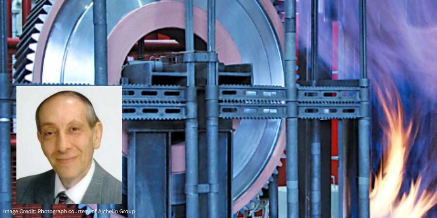
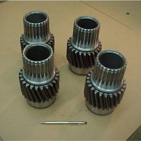
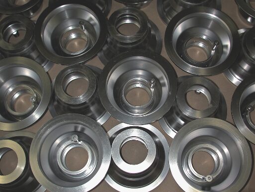
Gears play an essential role in the performance of many products that we rely on in our everyday lives. When we think about gears, we generally separate them into two categories: motion-carrying and power transmission. Motion-carrying gears are generally nonferrous alloys or plastics, while load bearing power transmission gears (Figure 1) are usually manufactured from ferrous alloys and are intended for heavy-duty service applications.
Figure 1. Typical off-highway truck power transmission gears | Image Credit: The Heat Treat Doctor®
Gear Materials & Engineering
Power transmission gears involve a wide variety of steels and cast irons. In all gears, the choice of material must be made only after careful consideration of the performance demanded by the application end-use and total manufactured cost, taking into consideration such issues as pre- and post-machining economics.
Key design considerations require an analysis of the type of applied load, whether gradual or instantaneous, and the desired mechanical properties, such as bending fatigue strength or wear resistance — all of which will define core strength and heat treating requirements.
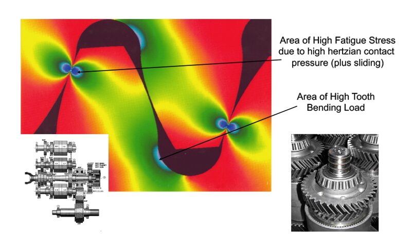
Figure 2. Stress profile in a heavy-duty transmission gear | Image Credit: The Heat Treat Doctor®
It is important for the designer to understand that each area in the gear tooth profile sees different service demands (Figure 2). Consideration must be given to the forces that will act on the gear teeth with tooth bending and contact stress, resistance to scoring and wear, and fatigue issues being paramount. For example, in the root area, good surface hardness and high residual compressive stress are desired to improve endurance or bending fatigue life. At the pitch diameter, a combination of high hardness and adequate subsurface strength are necessary to handle contract stress and wear and to prevent spalling.
Some of the factors that influence fatigue strength are:
Hardness distribution, a function of:
Case hardness
Case depth
Core hardness
Microstructure, a function of:
Retained austenite percentage
Grain size
Carbide size, type, and distribution
Non-martensitic phases
Defect control, a function of:
Residual compressive stress
Surface finish and geometry
Intergranular toughness
In the total manufacturing scheme, a synergistic relationship must exist between the material selection process, engineering design, and manufacturing (including heat treatment). A balance of the priorities in each discipline must be reached to achieve the optimization necessary for the ultimate performance of the gear design. This is often not an easy task.
Various atmosphere heat treatment methods are used for most types of gears including pre-hardening steps (e.g., annealing, normalizing, stress relief) and hardening processes (e.g., neutral hardening and case hardening).
Hardening
Neutral (aka through hardening) refers to heat treatment methods that do not produce a case. Examples of commonly through-hardened gear steels are AISI/SAE grades 1045, 4130, 4140, 4145, 4340, and 8640. It is important to note that hardness uniformity should not be assumed throughout the gear tooth. Since the outside of a gear is cooled faster than the inside, there will be a hardness gradient developed. The final hardness is dependent on the amount of carbon in the steel. The depth of hardness depends on the hardenability of the steel.
Through hardening can be performed either before or after the gear teeth are cut. When gear teeth will be cut after the part has been hardened, machinability becomes an important factor based on final hardness. The hardness is achieved by heating the material into the austenitic range, typically 815°C–875°C (1500°F–1600°F), followed by quenching and tempering.
Case Hardening
By contrast, case hardening is used to produce a hard, wear resistant case (surface layer) on top of a ductile, shock resistant interior (core). The idea behind case hardening is to keep the core of the gear tooth at a level under 40 HRC to avoid tooth breakage while hardening the outer surface to increase pitting resistance.
Carburizing
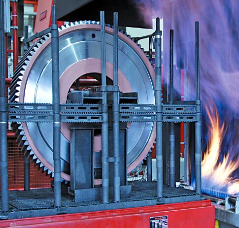
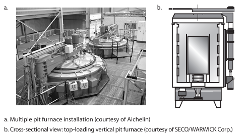
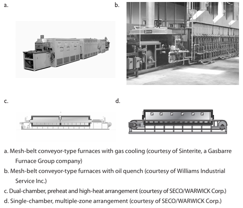
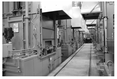
Figure 3. Atmosphere carburizing of large gears | Image Credit: Photograph courtesy of Aichelin Group
Atmosphere carburizing is the most common of the case hardening methods in use today and can handle a diverse range of part sizes and load configurations (Figure 3). In general, a properly carburized gear will be able to handle somewhere between 30–50% more load than a through-hardened gear. Examples of commonly carburized gear steels include AISI/SAE grades 1018, 4320, 5120, 8620, and 9310, as well as international grades, such as 20MnCr5, 17CrNiMo6, 18CrNiMo7-6, and 20MoCr4.
Atmosphere carburizing is typically performed in the temperature range of 870°C–955°C (1600°F–1750°F) although temperatures up to 1010°C (1800°F) are used for deep case work. Carburizing case depths can vary over a broad range, typically 0.13–8.25 mm (0.005–0.325 inches).
Carbonitriding
Carbonitriding is a modification of the carburizing process, not a form of nitriding. This modification consists of introducing ammonia into the carburizing atmosphere to add nitrogen to the carburized case as it is being produced. Examples of gear steels that are commonly carbonitrided include AISI/SAE 1018, 1117, and 12L14.
Carbonitriding is done at a lower temperature than carburizing, typically between 790°C–900°C (1450°F–1650°F), and for a shorter time. Combine this with the fact that nitrogen inhibits the diffusion of carbon, and what generally results is a shallower case than is typical for carburized parts. A carbonitrided case is usually between 0.075–0.75 mm (0.003–0.030 inches) deep.
Nitriding
Nitriding is another surface treatment process that has as its objective increasing surface hardness. One of the appeals of this process is that rapid quenching is not required, hence dimensional changes are kept to a minimum. It is not suitable for all gear applications; one of its limitations is that the extremely high surface hardness case produced has a more brittle nature than say that produced by the carburizing process. Despite this fact, in a number of applications, nitriding has proved to be a viable alternative. Examples of commonly nitrided gear steels include AISI/SAE 4140, 4150, 4340, and Nitralloy® 135M.
Nitriding is typically done in the range of 495°C–565°C (925°F–1050°F). Case depth and case hardness properties vary not only with the duration and type of nitriding being performed but also with steel composition, prior structure, and core hardness. Typically, case depths are between 0.20–0.65 mm (0.008–0.025 inches) and take from 10 to 80 hours to produce.
Nitrocarburizing (Ferritic or Austenitic)
Nitrocarburizing is a modification of nitriding, not a form of carburizing. In the process, nitrogen and carbon are simultaneously introduced into the steel while it is in a ferritic or at times an austenitic condition. A very thin “white” or “compound” layer is formed during the process, as well as an underlying “diffusion” zone. Like nitriding, rapid quenching is not required. Examples of gear steels that are commonly nitrocarburized include AISI/SAE grades 4140, 5160, 8620, and certain tool steels, such as H11 and H13.
Nitrocarburizing is normally performed at 550°C–600°C (1025°F–1110°F) and can be used to produce a 58 HRC minimum hardness, with this value increasing dependent on the base material. White layer depths range from 0.0013–0.056 mm (0.00005–0.0022 inches) with diffusion zones from 0.03–0.80 mm (0.0013–0.032 inches) being typical.
In Summary
There are many ways to heat treat gears. While atmosphere heat treatment (discussed above) is perhaps the most widely used technology today, other types of heat treatments, namely vacuum and induction hardening, are becoming more and more common methods. These will be discussed in Part Two.
About the Author
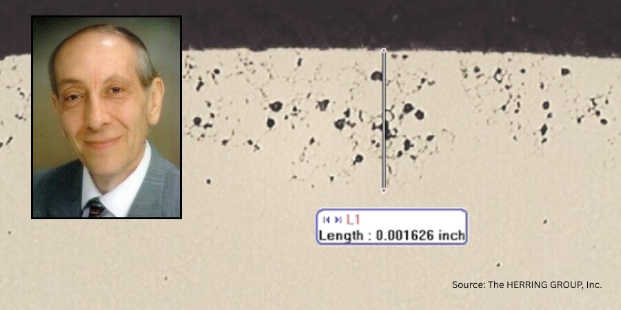
Dan Herring “The Heat Treat Doctor” The HERRING GROUP, Inc.
Dan Herring has been in the industry for over 50 years and has gained vast experience in fields that include materials science, engineering, metallurgy, new product research, and many other areas. He is the author of six books and over 700 technical articles.
A new study from the Umweltbundesamt (the Federal Environment Agency in Germany) outlines a clear, technically grounded pathway for achieving CO2-neutral process heat across energy-intensive industries. This Technical Tuesday installment highlights the study’s key findings, offering North American heat treaters a concise look at the technical feasibility, economic pressures, and strategic choice involved in moving beyond fossil-fuel-based thermal processing.
This informative piece was first released inHeat Treat Today’sJanuary 2026 Annual Technologies To Watch print edition.
Introduction
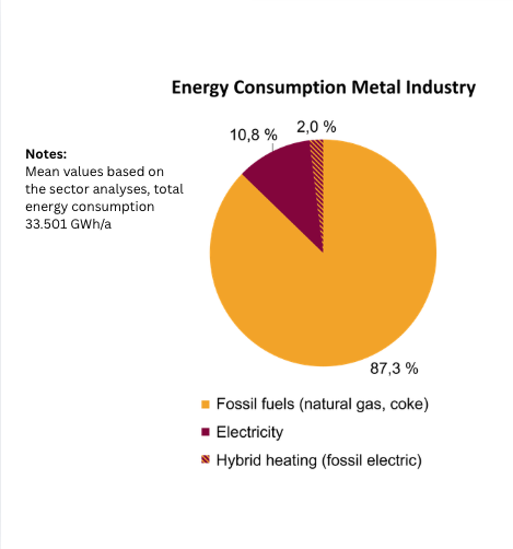
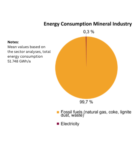
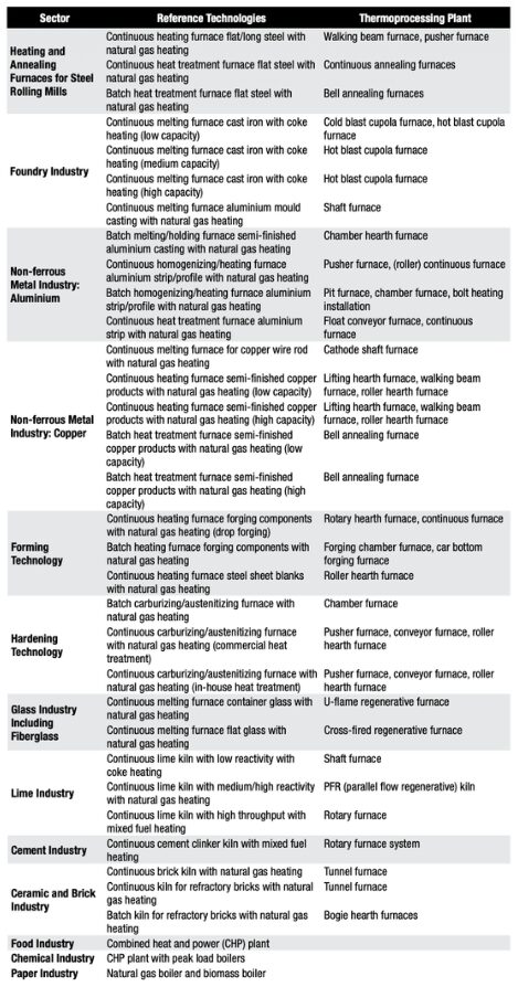
Figure 1. Metal Industry – distribution of total annual energy consumption by energy source | Image Credit: SchwotzerFigure 2. Mineral industry – distribution of total annual energy consumption by energy source | Image Credit: SchwotzerTable A. Overview Examined Dectors, Associated Reference Technologies, and Thermal Processing Systems | Image Credit: Schwotzer
Efforts to mitigate climate change are crucial, particularly in Germany where there is a significant amount of energy-intensive industry, to achieve ambitious climate targets while preserving jobs and international competitiveness. Currently, process heat generation is heavily dependent on the use of fossil fuels, especially natural gas, with a low utilization of renewable energies. Fossil energy sources dominate the metal industry, accounting for 87.3%, while electricity represents 10.8%, and hybrid heating systems make up 2.0%. The mineral industry shows an even stronger dependence, with fossil fuels accounting for 99.7%. These figures illustrate the challenges and potential for technological innovations to provide CO2-free process heat in these sectors.
Although some sectors are already either using technologies for CO2-neutral process heat supply or are planning to do so, there is no comprehensive overview of the technical possibilities for generating process heat in energy-intensive industries in the context of future economic framework conditions.
In this study, technologies for the CO2-neutral supply of process heat are considered from a technical, economic, and ecological perspective. The study was conducted for thirteen industries and thirty-four exemplary applications in the metals and minerals industries, as well as for the cross-cutting technology steam generation industry (Table A). For each application, alternative CO2-neutral technologies are examined for their technical feasibility, economic viability, and ecological impact. The focus is on the electrification of plant technology, the use of hydrogen, but also hybrid systems, and, in some cases, the use of biomass. From this comprehensive review of the current situation and the possible alternative technologies, findings and recommendations for implementation will be developed for industry, policymakers, and researchers to support the transformation to CO2-neutral process heat generation.
Study Method
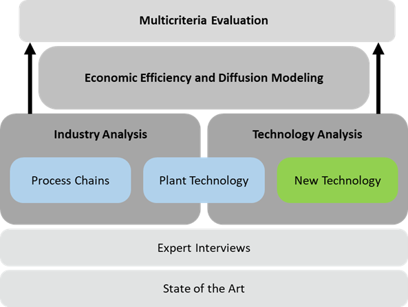
Figure 3. Study approach | Image Credit: Schwotzer
The study is based on an industry and technology assessment of the state of the technology (Figure 3). The results from the metal and mineral industries and the cross-sectional technology of steam generation were analyzed and summarized in consultation with experts. The central process chains were examined for each sector and the most important processes in terms of energy were identified. Each process chain contains several processes in which specific thermal process plants (industrial furnaces) are used, which are grouped into plant types. Based on the selected processes and plant types, applications are defined for further consideration. A reference technology and two to four CO2-neutral alternative technologies (new technologies) are assigned to each application. Key figures such as specific energy requirements, process-related emissions, or investment costs are used for comparison.
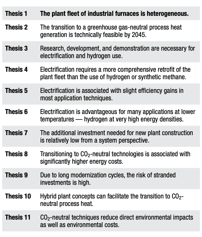
Table B. Theses Summary of Study Results | Image Credit: Schwotzer
The central findings of the study are summarized in eleven theses on the transformation of process heat generation (Table B). In this article, Theses 1, 2, 6, and 9 are presented in detail, providing a broad overview of the essential findings. For a more in-depth examination of the theses, see the link to the original study.
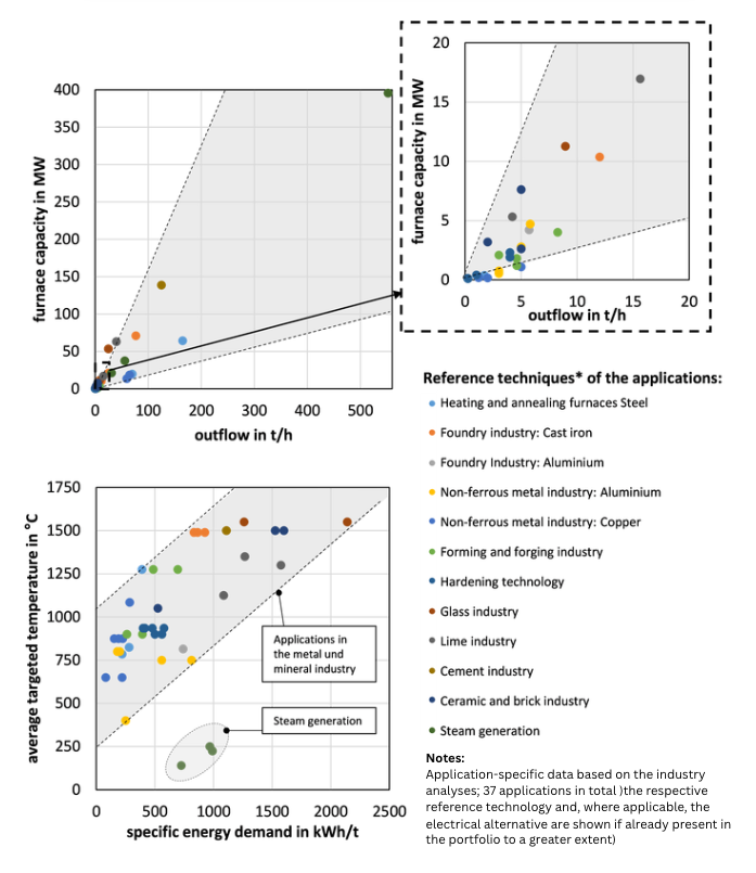
The Plant Fleet of Industrial Furnaces is Heterogeneous
The metal and mineral industries are characterized by numerous small process plants (throughput of less than 20 tons per hour and plant capacity of less than 20 MW). At the same time, there are large facilities with significantly higher throughput and corresponding higher plant capacities. Figure 4 shows a selection of technical examples from the study. Examples of large plants include heating and annealing furnaces in the steel industry with capacities of up to 170 tons per hour or cathode shaft furnaces in the copper industry with throughputs of up to 80 tons per hour. It is observed that the specific energy requirement of a plant correlates with the process temperature. The higher the required temperature of a process, the higher the specific energy requirement.
Figure 4. Classification of the considered applications and reference technologies in the plant fleet in Germany based on characteristic parameters | Image Credit: Schwotzer
Additionally, the cross-sectional technology of steam generation was examined. The most up to date technology includes natural gas boilers or combined heat and power (CHP) systems. Industry-specific characteristics play a minor role in the selection of technology for achieving CO2 neutrality. The technical requirements for end applications are less different compared to industrial furnaces. This includes performance, throughput, pressure, and temperature.
A transition to CO2-neutral process heat generation encompasses various technical possibilities and obstacles, as well as investment costs and space requirements, depending on the industry and application. Accordingly, the necessary adaptation measures require a differentiated approach to the transition to CO2-neutral process heat generation. An effective strategy to achieve CO2 neutrality should take into account the unique characteristics of each industry’s production processes, as well as the specific challenges and opportunities they present.
Technical Transformation to CO2-Neutral Production is Feasible
Despite the wide variety of plants and specific challenges, the transition to CO2-neutral process heat generation is technically feasible by 2045. The solutions will vary depending on the industry and application, and the effort required to transition from currently used reference technologies to CO2-neutral alternatives varies significantly.
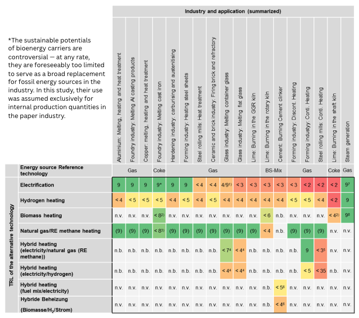
The heterogeneity of industrial furnaces has a significant impact on the feasibility of deploying CO2-neutral technology in the future. While electrification is already highly advanced and most up to date in applications such as the foundry industry, bulk forming, or melting of aluminium with induction furnaces, it shows comparatively low technological maturity in sectors like the lime and cement industry, which are associated with fundamental technical challenges; see Figure 5. This significant heterogeneity in the existing plant stock and terms of technology readiness level (TRL) (European Commission 2014) requires consideration in transformation strategies.
Figure 5. Technology readiness level (TRL) of the alternative technologies (summarized) | Image Credit: Schwotzer
Both hydrogen and electrification can have a significant impact, although further research and development are needed in many areas. Across applications, it is evident that electrification generally requires the construction of new facilities. Transitioning from natural gas-operated reference technology to hydrogen involves less technical effort in terms of plant technology and can be accomplished by retrofitting the burner technology. Additionally, using hydrogen requires local infrastructure (pipes, valves) and its impacts on process and product quality need to be tested. Industrial-scale facilities are not yet available, resulting in a TRL of < 5, according to the study. However, with ongoing research and development in many projects, the TRL for many applications is expected to rise quickly in the coming years.
Scaling all alternative technologies to an industrial level and testing them in operational deployments are crucial. Some technologies face significant technical barriers, such as the continuous heating in steel rolling mills. These processes and their plant technology are characterized by very high process temperatures and production capacities, requiring heating technologies with a high energy density, which are not possible with current most cutting-edge electrical heating technologies. The use of hydrogen also presents a particular technological challenge, especially in areas where solid fuels like coke are currently used, such as in shaft kilns for lime burning or in cupola furnaces of iron foundries. As a result, alternative, bio-based fuels are being considered for these applications.
However, for these fuels to be a viable option, they need to be produced in sufficient quantity and quality. On the other hand, CO2-neutral techniques for steam generation using hydrogen and for electrification are already available for industrial use today.
The continuation of this article will be released in Heat TreatToday’sSustainable Heat Treating Technologies edition (May 2026) where electrification versus hydrogen and a frank reckoning with the cost of new investments will be examined.
References
European Commission. 2014. Annex G – Technology Readiness Levels (TRL). Extract from Part 19 – Commission Decision C(2014)4995, “Horizon 2020 – Work Programme 2014–2015. General Annexes.” Brussels: European Commission.
Fleiter, Tobias, et al. 2023. CO2-Neutrale Prozesswärmeerzeugung: Umbau des industriellen Anlagenparks im Rahmen der Energiewende. Dessau-Roßlau: German Environment Agency (Umweltbundesamt).
All results in this article derive from the study “CO2-neutral process heat generation” (German: „CO2-neutrale Prozesswärmeerzeugung – Umbau des industriellen Anlagenparks im Rahmen der Energiewende: Ermittlung des aktuellen SdT und des weiteren Handlungsbedarfs zum Einsatz strombasierter Prozesswärmeanlagen”). The authors of this article would like to thank everyone who contributed to the study, listed in the published study. The study and further documents are on the website of the Federal Environment Agency in Germany (Umweltbundesamt).
This editorial is published with permission from Heat TreatToday’s media partner heat processing, which published this article in March 2024.
About The Authors:
Dr. Christian Schwotzer Department for Industrial Furnaces and Heat Engineering RWTH Aachen University, Germany schwotzer@iob.rwth-aachen.de
Katharina Rothhöft, M.Sc. Department for Industrial Furnaces and Heat Engineering RWTH Aachen University, Germany rothhoeft@iob.rwth-aachen.de
Un austenizado insuficiente afecta mucho más que la dureza final. Interrumpe la transformación de fase, debilita el rendimiento mecánico y aumenta el riesgo de deformación o fallo en condiciones de servicio exigentes. En esta entrega de Technical Tuesday, Ana Laura Hernández Sustaita, fundadora de Consultoría Carnegie, explica los orígenes metalúrgicos de la formación incompleta de la austenita; como la uniformidad del horno, la velocidad calentamiento, la composición química del acero y la geometría de la pieza, contribuyen a ese problema; y las estrategias modernas de control de procesos y simulación que garantizan una transformación completa y resultados repetibles de alta calidad.
Este artículo informativo se publicó por primera vez enHeat Treat Today’sJanuary 2026 Annual Technologies To Watch print edition.
En inglés, el término underhardening se utiliza para describir aceros que no alcanzan una austenización completa, lo que se traduce en una pérdida de dureza después del temple. Sin embargo, en este artículo ampliaremos el análisis más allá de la dureza, centrándonos en el fenómeno de la austenización insuficiente, analizando sus causas, su influencia directa en la microestructura y en las propiedades mecánicas, así como las acciones que podemos implementar en el proceso para prevenirla.
El rol del proceso de austenización
El objetivo principal del tratamiento térmico es obtener una microestructura homogénea o mixta que garantice las propiedades mecánicas requeridas para las condiciones de servicio establecidas: resistencia a la tracción, resistencia al impacto, límite elástico, entre otras.
El proceso de austenización es el primer paso crítico para muchos procesos. Consiste en calentar el acero por encima de la temperatura A3 (normalmente entre 30 y 50°C/85 y 120°F adicionales) para obtener una microestructura con red cúbica centrada en las caras (FCC) durante un tiempo determinado. Este paso es fundamental después de procesos como solidificación, forja o laminado, ya que “reinicia” la historia microestructural del acero.
¿Qué es la austenización insuficiente?
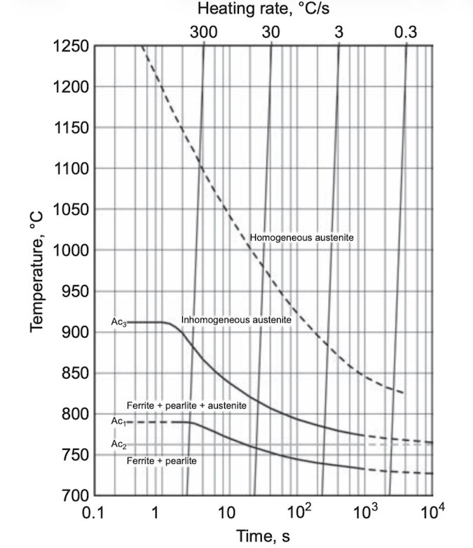
Figura 1. Diagrama tiempo-temperatura de austenización para acero Ck 45 (SAE/AISI 1045). | Image Credit: Figure 7, ASM International 2013
La formación de austenita implica cambios estructurales y composicionales influenciados tanto por la microestructura inicial como por la composición química del acero. Cuando los parámetros de austenización no se establecen adecuadamente: temperatura insuficiente, tiempo de permanencia corto o problemas de desempeño del equipo, como la falta de uniformidad térmica del horno, la transformación no se completa. El resultado es una microestructura que conserva fases no deseadas, lo que afecta la dureza, la estabilidad dimensional y la resistencia mecánica. Por lo tanto, cualquier microestructura que no logre transformarse completamente a austenita debido a los factores mencionados puede considerarse un caso de austenización insuficiente.
Causas de la Austenización Insuficiente:
Temperatura de austenización inadecuada: si la temperatura es demasiado baja, no se logra la disolución completa de ferrita o carburos.
Tiempo de empape insuficiente: un tiempo de empape (permanencia) demasiado corto impide la difusión homogénea del carbono en la austenita.
Distribución térmica no uniforme en el horno: produce zonas con distintos grados de transformación.
Composición química del acero: los elementos de aleación modifican la cinética de difusión y desplazan las temperaturas críticas de transformación.
Geometría y dimensiones de la pieza: las secciones más grandes demandan mayor tiempo de empape, para alcanzar el calentamiento completo.
Velocidades de calentamiento rápidas: pueden impedir la homogeneización de la microestructura y generar una transformación incompleta, especialmente en procesos por inducción.
Efectos de una austenización insuficiente
Microestructura heterogénea
Tal como se ilustra en el ASM Handbook, Volume 4A: Steel Heat Treating Fundamentals and Processes, la cinética de formación de la austenita depende fuertemente de la velocidad de calentamiento. A bajas velocidades, la homogeneización por difusión ocurre a temperaturas relativamente menores; en contraste, los calentamientos rápidos generan heterogeneidad microestructural, un efecto especialmente crítico en procesos como el endurecimiento por inducción o el calentamiento directo por flama. En otras palabras, la austenización insuficiente se presenta con mayor frecuencia cuando se emplean altas velocidades de calentamiento.
En consecuencia, una microestructura con composición heterogénea provoca variaciones en las temperaturas de transformación martensítica (Ms y Mf) a lo largo de la pieza. Durante el temple, las regiones con menor contenido de carbono transforman primero, originando una martensita más suave, mientras que las zonas más ricas en carbono transforman a menores temperaturas, generando tensiones internas y una microestructura inconsistente.
Mayor riesgo de deformaciones y fallas prematuras en servicio
Anteriormente se mencionó que el proceso de austenización implica un cambio en la estructura cristalina del material. Si este cambio no es homogéneo a lo largo de la pieza, se presentarán diferentes fases, resultando en un arreglo cristalográfico variado y, por ende, un cambio volumétrico. Por otra parte, calentar una pieza muy rápidamente provoca que el calor no se distribuya ni penetre de manera uniforme, causando transformaciones heterogéneas y, por lo tanto, tensiones debido a los cambios volumétricos en la estructura cristalina.
Reducción en la dureza y resistencia mecánica
Una austenización incompleta deja restos de ferrita o carburos no disueltos en la microestructura, que impide la transformación completa a martensita durante el temple, reduciendo la dureza final. Además, una menor cantidad de carbono en solución afecta negativamente la resistencia mecánica.
Aumento de la fragilidad y menor tenacidad
Una microestructura heterogénea (ferrita y perlita con martensita parcial y austenita retenida) disminuye la resistencia mecánica. Esto se traduce en menor capacidad para soportar cargas sin fracturarse.
Como prevenir la austenización ineficiente
Control preciso de temperatura y tiempo del horno
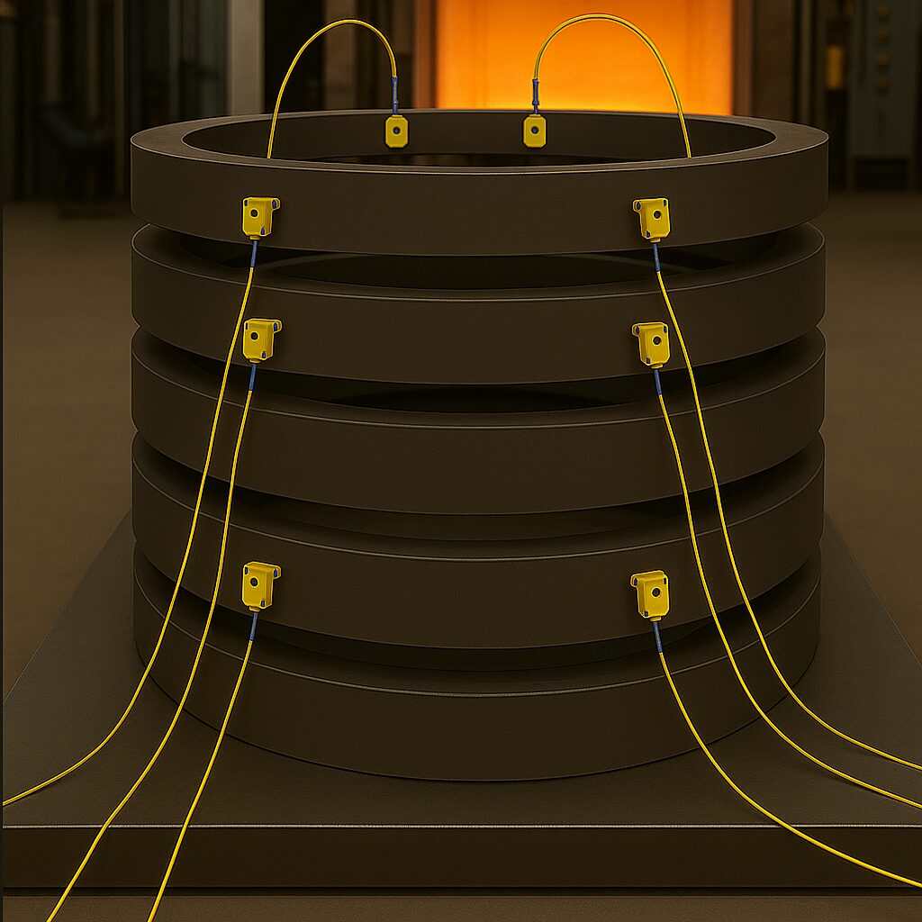
Figura 2. Ejemplo de un análisis de carga | Image Credit: Consultoría Carnegie
Para garantizar un control adecuado durante el mantenimiento, es fundamental utilizar termopares calibrados y ubicarlos estratégicamente dentro del horno para asegurar mediciones precisas. La calibración periódica previene errores en la lectura de temperatura, lo que contribuye directamente a la calidad del proceso. Además, es indispensable contar con la asesoría de un experto para determinar la vida útil recomendada de los termopares. Mantener una trazabilidad adecuada y realizar los reemplazos en tiempo y forma asegurará un funcionamiento óptimo del sistema.
Por otra parte, el uso de ventiladores internos en hornos de convecciones nos ayudara a mantener una uniformidad térmica dentro del horno, evitando zonas frías o calientes.
Otra forma de poder controlar la temperatura del proceso es el uso de registradores de temperatura o graficadores de temperatura. Estos dispositivos, conectados a termopares de contacto instalados directamente en las piezas, son especialmente recomendables para componentes con geometrías complejas con grandes espesores. Su función es registrar la temperatura en tiempo real y verificar que no existan fluctuaciones durante el tiempo de mantenimiento.
Distribución adecuada de la carga
En cargas donde es necesario realizar el tratamiento térmico de una cantidad considerable de piezas, es recomendable llevar a cabo un estudio para determinar la altura máxima de apilamiento que permita un flujo de calor adecuado y un calentamiento homogéneo. Un análisis preliminar puede realizarse colocando termopares estratégicamente en diferentes ubicaciones y en distintas piezas: por ejemplo, en la primera pieza de la carga, otra en la parte media y una más en la parte inferior de la torre de apilamiento.
Una vez que las piezas ingresan al proceso, es posible monitorear el comportamiento térmico de cada una de ellas, verificando que el tiempo de empape sea suficiente para que todas alcancen la transformación requerida al llegar a la temperatura objetivo, o bien, determinar si es necesario realizar ajustes en la configuración de la carga.
Uso simulación termodinámica para optimizar los parámetros del proceso
Cada grado de acero tiene una temperatura óptima de austenización determinada por su composición química. En los aceros al carbono (serie 10xx), estas temperaturas pueden estimarse mediante el diagrama Fe–C; sin embargo, cuando se incorporan elementos de aleación, dicho diagrama deja de ser suficiente. En esos casos, es necesario recurrir al cálculo de temperaturas críticas o al uso de herramientas más precisas, como simulaciones termodinámicas mediante software especializado, por ejemplo, Thermo-Calc®.
Aunque lo ideal sería tratar cada material a su temperatura específica, en la producción industrial esto no es eficiente, ya que implicaría procesar cada pieza de manera individual, lo cual ralentizaría la línea de fabricación y aumentaría el consumo de recursos, como tiempo y gas.
El uso de herramientas termodinámicas como ThermoCalc software ® permite evaluar cómo las variaciones en la composición química (debidas a tolerancias de colada o ajustes en elementos de aleación) afectan las temperaturas de transformación. Esto facilita la selección de una temperatura óptima de proceso que garantice que, para cada composición posible dentro de las especificaciones, las temperaturas de austenización sean las adecuadas. Con ello se optimiza el rendimiento del tratamiento térmico y se mejora la reproducibilidad del proceso.
Por ejemplo, en la figura 3, si un acero 4140 se calienta únicamente a 750°C (1380°F) en lugar de 850°C (1560°F), la ferrita no se disolverá por completo. Como resultado, después del temple se obtendrá una microestructura compuesta por martensita blanda y ferrita residual, en lugar de una martensita homogénea y dura. Esto reduce significativamente la dureza y la resistencia mecánica del material.
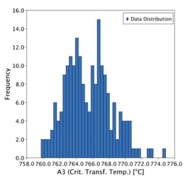
Figura 3. Diagrama de un eje para un acero 4140, (Fe, 0.4C, 0.8Mn, 0.2Si, 0.8Cr, 0.2Mo, 0.02Ni) | Image Credit: Consultoría Carnegie Figura 4. Histograma de la temperatura de transformación Ac3 para un acero AISI 4140 dentro del rango de especificación. | Image Credit: Consultoría Carnegie
En el histograma (figura 4) podemos observar que, incluso tratándose del mismo grado de acero, la temperatura A₃ puede variar aproximadamente 760−776°C (1400−1429°F) únicamente debido a las tolerancias químicas establecidas en la especificación. Si además consideramos la presencia de elementos residuales o microaleantes, es evidente que no podemos esperar el mismo comportamiento durante el tratamiento térmico ni las mismas propiedades mecánicas en todas las coladas.
En estos casos, herramientas termodinámicas como ThermoCalc software® permiten evaluar un conjunto amplio de posibles composiciones químicas y determinar una temperatura de austenización óptima que sea adecuada para todas las variaciones permitidas dentro de la especificación.
Diseño de curvas/rampas de calentamiento
Para asegurar que las temperaturas de transformación se alcancen de manera homogénea (tanto en procesos con cargas de alto volumen, como en piezas con geometrías variables) es recomendable implementar un calentamiento controlado. Aunque esto puede aumentar el tiempo de procesamiento, los beneficios incluyen una menor probabilidad de distorsión y la garantía de lograr una transformación austenítica completa.
La clave radica en diseñar un perfil adecuado de tiempo–temperatura, el cual dependerá de factores como las dimensiones de la pieza y las propiedades del material, entre ellas: difusividad térmica, capacidad calorífica, densidad y conductividad térmica.
Conclusión
La austenización insuficiente, conocida como underhardening, representa mucho más que una simple pérdida de dureza. Es una deficiencia metalúrgica que afecta la homogeneidad microestructural, la estabilidad dimensional y el desempeño mecánico.
Mediante un control riguroso de la temperatura, el tiempo y la uniformidad del horno, combinado con herramientas modernas de simulación, los ingenieros pueden asegurar transformaciones confiables, minimizar la distorsión y lograr resultados constantes y de alta calidad en el tratamiento térmico de los aceros.
Callister, W. D. 2019. Materials Science and Engineering: An Introduction. Hoboken, NJ: Wiley.
Herring, Dan. Metallurgical Fundamentals of Heat Treatment. Industrial Heating.
Krauss, G. 1980. Principles of Heat Treatment of Steel. ASM International.
Nuñez González, G. 1990. Fallas en los Tratamientos Térmicos para Aceros Herramienta.
Thomas, L. 2018. “Austenitizing Part 2: Effects on Properties.” Knife Steel Nerds. https://knifesteelnerds.com/2018/03/01/austenitizing-part-2-effects-on-properties/.
Totten, G. E. 2007. Steel Heat Treatment: Metallurgy and Technologies. Boca Raton, FL: CRC Press.
Acerca de la autora:
Ana Laura Hernández Sustaita Fundadora Consultoría Carnegie
Ana Laura Hernández Sustaita cuenta con Maestría en Ciencia e Ingeniería de los Materiales, Es fundadora de Consultoría Carnegie, una firma de consultoría y capacitación técnica especializada en el tratamiento térmico de aceros en México. Asimismo, se desempeña como Ingeniera de Soporte Técnico en Thermo-Calc Software, brindando asistencia a clientes en México, Canada y Estados Unidos de América. Ana promueve activamente la educación metalúrgica en Latinoamérica y fomenta la integración de herramientas computacionales en la práctica industrial del tratamiento térmico.
Insufficient austenitizing affects far more than final hardness. It disrupts phase transformation, weakens mechanical performance, and increases the risk of distortion or failure in demanding service conditions. In this Technical Tuesday installment, Ana Laura Hernández Sustaita, founder of Consultoría Carnegie, explains the metallurgical origins of incomplete austenite formation, how furnace uniformity, heating rate, steel chemistry, and part geometry contribute to the problem, and modern process-control and simulation strategies that ensure full transformation and repeatable, high-quality results.
This informative piece was first released inHeat Treat Today’sJanuary 2026 Annual Technologies To Watch print edition.
When a steel part is insufficiently austenitized, it is commonly referred to as underhardening, the resulting loss of hardness after quenching. However, in this article, we will extend the discussion beyond hardness alone, exploring the phenomenon of insufficient austenitizing, analyzing its causes and direct influence on microstructure and mechanical properties, and discussing modern strategies to prevent it.
The Role of Austenitizing in Heat Treatment
The main purpose of heat treatment is to produce a homogeneous or a desired mixed microstructure that ensures the required mechanical properties for the intended service conditions: tensile strength, impact resistance, yield strength, etc. Austenitizing is the first critical step for many processes. It involves heating the steel above the A3 temperature (typically 30–50°C or 85–120°F higher) to transform its microstructure into a face-centered cubic (FCC) lattice for a certain period of time. This step resets the steel’s structural history, particularly after casting, forging, or rolling, and defines the baseline for subsequent quenching and tempering operations.
What Is Insufficient Austenitizing?
Figure 1. Time-temperature-austenitization diagram for Ck 45 (SAE/AISI 1045) steel. | Image Credit: Figure 7, ASM International 2013
Austenite formation involves structural and compositional changes influenced by the initial microstructure and the steel’s chemical composition. When austenitizing parameters are not properly established, such as insufficient temperature, inadequate soaking time, or poor furnace performance (e.g., lack of thermal uniformity), the transformation remains incomplete. The result is a microstructure containing undesired residual phases that compromise hardness, dimensional stability, and mechanical strength. Therefore, any microstructure that fails to fully transform to austenite due to these factors can be directly associated with insufficient austenitizing.
Common causes of insufficient austentizing include:
Inadequate austenitizing temperature: Ferrite and carbides do not fully dissolve if the temperature is too low.
Insufficient holding time: A short soak time prevents uniform carbon diffusion throughout the austenite.
Thermal non-uniformity in the furnace (cold zones): This leads to regions with different degrees of transformations.
Chemical composition of the steel: Alloying elements modify diffusion kinetics and impact the critical transformation temperatures.
Geometry and dimensions of the part: Larger cross-sections require longer soak times for full heat diffusivity.
Rapid heating rates: Excessive heating, especially during induction hardening, can result in structural inhomogeneity and incomplete transformation.
Effects of Insufficient Austentizing
Heterogeneous Microstructure
As illustrated in the ASM Handbook, Volume 4A: Steel Heat Treating Fundamentals and Processes (2013), the kinetics of austenite formation depend strongly on the heating rate. At lower heating rates, diffusion-driven homogenization occurs at relatively lower temperatures, whereas rapid heating produces microstructural heterogeneity, an effect that is especially critical in induction or direct-flame heating. In other words, insufficient austenitizing is more likely to occur when high heating rates are used.
Consequently, a microstructure with heterogeneous composition leads to variations in the martensite transformation temperatures (Ms and Mf) throughout the part. During quenching, regions with lower carbon content transform earlier, producing softer martensite, while areas with higher carbon content transform at lower temperatures, resulting in internal stresses and an overall inconsistent microstructure.
Risk of Distortion and Premature Failure
The transformation from BCC or BCT to FCC (Defined: BCC: body-centered cubic; BCT: body-centered tetragonal; FCC: face-centered cubic) lattice during austenitizing involves a specific volume change. If this transformation occurs unevenly, differential expansion generates internal stresses, distortion, and in severe cases, microcracks. Rapid heating or poor furnace convection exacerbates these effects by producing steep temperature gradients across the part.
Reduced Hardness and Mechanical Strength
Incomplete transformation leaves undissolved carbides and residual ferrite, reducing hardenability and the amount of carbon in solid solution. This limits the formation of martensite during quenching and lowers final hardness and strength.
Increased Brittleness and Lower Toughness
A mixed structure of ferrite, pearlite, partial martensite, and retained austenite results in mechanical anisotropy and reduced energy absorption under impact loading. This condition increases the risk of brittle fracture, particularly in high-stress or cyclic applications.
How to Prevent Insufficient Austenitizing
Accurate Furnace Control
Figure 2. Example of loading analysis | Image Credit: Consultoría Carnegie
To ensure proper process control during the soaking stage, it is essential to use calibrated thermocouples strategically positioned inside the furnace to obtain accurate temperature measurements. Regular calibration prevents temperature reading errors and directly contributes to heat treatment quality. It is also important to get advice from an expert to determine the recommended service life of the thermocouples. Maintaining proper traceability and replacing them at the appropriate intervals ensures optimal system performance.
Additionally, the use of internal circulation fans in convection furnaces helps maintain thermal uniformity, preventing the formation of hot or cold zones.
Another method to monitor and control process temperature is using temperature data loggers. These devices, which are connected to contact thermocouples and placed directly on the parts, are especially recommended for components with complex geometries or large cross-sections. They record real-time temperature data throughout the process, allowing verification that no transient fluctuations occur during the soaking period.
Accurate Loading Distribution
For loads where heat treatment must be applied to a significant number of parts, it is recommended that a study be conducted to determine the maximum stacking height that will ensure proper heat flow and uniform heating. A preliminary assessment can be performed by strategically placing thermocouples in different locations and on different parts, for example, on the first part in the load, one in the middle section, and another at the bottom of the stacking tower.
Once the parts enter the process, their heating behavior can be monitored to verify that the soaking time is sufficient for all pieces in the stack to complete their transformation upon reaching the target temperature or to determine whether adjustments to the loading configuration are necessary.
Use of Thermodynamic Simulation to Optimize Process Parameters
Each steel grade has an optimum austenitizing temperature in function of its chemical composition. For carbon steels (10XX series), these temperatures can be estimated using the Fe–C diagram; however, once alloying elements are added, this diagram is no longer sufficient. In such cases, it becomes necessary to rely on critical temperature calculations or on more advanced tools such as thermodynamic simulations using specialized software, like Thermo-Calc®.
Although the ideal scenario would be to heat treat each material at its specific optimum temperature, this approach is impractical in industrial production; the required processing of each part individually would slow the manufacturing line and increasing resource consumption, including time and fuel.
Thermodynamic tools such as Thermo-Calc allow engineers to evaluate how variations in chemical composition (arising from casting tolerances or adjustments in alloying elements) affect transformation temperatures. This enables the selection of an optimum processing temperature that ensures complete austenitization for all possible compositional variations within the specification. As a result, the heat treatment operation becomes more robust, more reproducible, and more energy efficient.
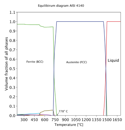
For example, in Figure 3, if a 4140 steel is heated only to 750°C (1380°F) instead of 850°C (1560°F), the ferrite will not fully dissolve. As a result, the microstructure will consist of soft martensite and residual ferrite after quenching, rather than a fully homogeneous and hard martensitic structure. This significantly reduces the material’s hardness and mechanical strength.
Figure 3. Equilibrium diagram, AISI 4140 0.38C, 0.78Mn, 0.85Cr, 0.22Mo (%wt.) | Image Credit: Consultoría CarnegieFigure 4. Histogram of Ac3 transformation temperature for AISI 4140 steel within the specification range. | Image Credit: Consultoría Carnegie
We can observe in the histogram (Figure 4) that even within the same steel grade, the A3 temperature can vary from approximately 760−776°C (1400−1429°F) solely due to the composition tolerances specified for the alloy. If we also consider the presence of residual or microalloying elements, it becomes clear that we cannot expect identical behavior during heat treatment or identical mechanical properties across all heats.
In such cases, thermodynamic tools allow us to evaluate a batch of possible chemistries and determine an optimal austenitizing temperature that is suitable for all compositional variations.
Heating Curve Design
To ensure that transformation temperatures are reached uniformly (whether in processes involving large loads or parts with variable geometries), it is advisable to implement controlled heating rates. Although this approach may increase processing time, the benefits include reduced distortion risk and assurance of complete austenitic transformation.
The key is to design an appropriate time–temperature profile, which depends on factors such as part dimensions and material properties, including thermal diffusivity, heat capacity, density, and thermal conductivity.
Conclusion
Insufficient austenitizing, also known as underhardening, represents far more than a loss of hardness. It is a metallurgical deficiency that affects microstructural homogeneity, dimensional stability, and mechanical performance. Through rigorous control of temperature, time, and furnace uniformity combined with modern simulation tools, engineers can ensure reliable transformations, minimize distortion, and achieve consistent high-quality results in steel heat treatment.
Callister, W. D. 2019. Materials Science and Engineering: An Introduction. Hoboken, NJ: Wiley.
Herring, Dan. Metallurgical Fundamentals of Heat Treatment. Industrial Heating.
Krauss, G. 1980. Principles of Heat Treatment of Steel. ASM International.
Nuñez González, G. 1990. Fallas en los Tratamientos Térmicos para Aceros Herramienta.
Thomas, L. 2018. “Austenitizing Part 2: Effects on Properties.” Knife Steel Nerds. https://knifesteelnerds.com/2018/03/01/austenitizing-part-2-effects-on-properties/.
Totten, G. E. 2007. Steel Heat Treatment: Metallurgy and Technologies. Boca Raton, FL: CRC Press.
About The Author:
Ana Laura Hernández Sustaita Founder Consultoría Carnegie
Ana Laura Hernández Sustaita holds a Master’s degree in Materials Science and engineering. She is the founder of Consultoría Carnegie, a technical consulting and training firm specializing in steel heat treatment in Mexico. Additionally, she works as a technical support engineer at Thermo-Calc Software, providing assistance to clients across México, Canada, and United States of America. Ana actively promotes metallurgical education throughout Latin America and advocates for the integration of computational tools into industrial heat treatment practice.
Ask The Heat Treat Doctor® has returned to bring sage advice to Heat Treat Today readers and to answer your questions about heat treating, brazing, sintering, and other types of thermal treatments as well as questions on metallurgy, equipment, and process-related issues.In this installment, Dan Herring explains how partial pressure atmospheres prevent evaporation and achieve bright, oxide-free parts in vacuum furnaces.
This informative piece was first released in Heat Treat Today’sDecember 2025 Annual Medical & Energy Heat Treat print edition.
Have questions or feedback? We’d love to hear from you — reach out to our editorial team at editor@heattreattoday.com.
Operating in vacuum can often lead to problems related to evaporation, that is, literally “boiling away” elements present in the materials being heat treated. This affects surface integrity, functionality, performance, and in some rare cases altering the chemical composition of the base (or filler) metal.
One way to overcome this problem is to introduce a gas partial pressure higher than that of the material’s vapor pressure. Different gas choices, introduction methods, and controls are available to the heat treater. The natural question is, how and when should they be used? Let’s learn more.
What is Partial Pressure?
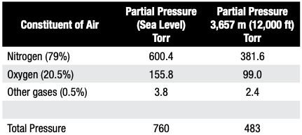
In simplest terms, the partial pressure of a gas introduced into a vacuum furnace is the force exerted by that gas (or gases) constrained in the vacuum vessel. If only a single gas is present, the partial pressure of the system is the same as the total pressure. For a multi-gas system, air is a good example to look at. At sea level with atmospheric pressure 760 torr (760 mm Hg) and at an altitude of 3,657 m (12,000 ft), the atmospheric pressure is only 483 Torr (Table A).
Table A. Partial Pressure of Individual Gases Present in Air | Source: Jones 1997
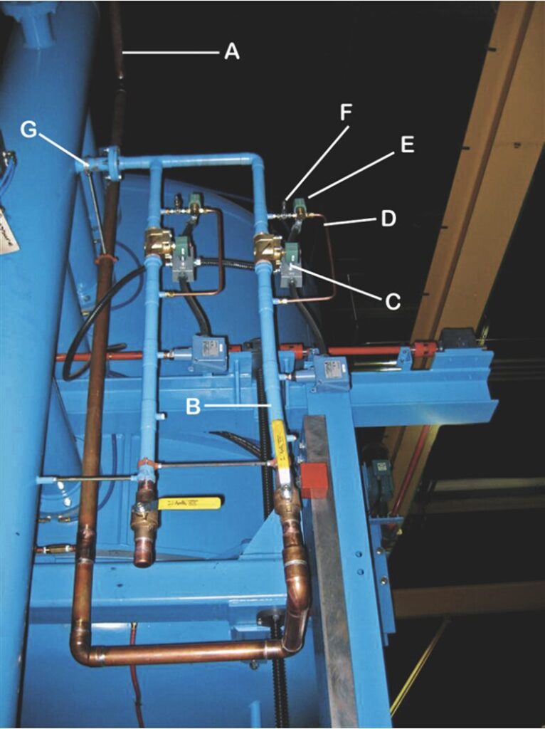
In vacuum systems, when the chamber atmosphere is evacuated to a high enough vacuum level — commonly between 10⁻³ Torr (0.1 micron) and 10⁻⁵ Torr (0.01 microns) — issues of evaporation are likely to occur during heat up and holding at temperature. As such, nitrogen or a truly inert gas is introduced below a predetermined temperature at a controlled rate to a fixed partial pressure range and then controlled within this range. One then isolates the high vacuum portion of the pumping system and employs bypass circuitry using the mechanical pump to introduce a continuous flow of gas equal to the pumping capacity (throughput) at the required operating pressure (Figure 1 below).
Figure 1. Typical partial pressure piping on a vacuum furnace Key: A: Incoming gas supply line B: Backfill line C: Quench solenoid D: Partial pressure line E: Partial pressure solenoid valve F: Partial pressure (micrometer) needle value G: Inlet into furnace Source: Courtesy of Vac-Aero International
Why Do We Need to Use Partial Pressure in a Vacuum Furnace?
There is no hard and fast rule for partial pressure settings used for processing various materials in the heat treat industry. However, from a practical standpoint, there are two process considerations for determining partial pressure. The first is the metal-oxide reduction partial pressure. The partial pressure of oxygen at a given temperature determines the direction of the reaction and consequently whether the part is “bright” or “discolored” (oxidized). These values are typically in the range of 10⁻⁶ Torr to 10⁻² Torr. This is why materials like titanium alloys and superalloys must be processed at extremely low vacuum levels. The second consideration is the vaporization of metal at high temperature and hard vacuum. The metal solid-to-vapor partial pressures require higher pressures to avoid alloy depletion. These higher pressures often produce sufficient dilutions of contaminants to drive the reaction to be reducing.
What is often overlooked or misunderstood is that higher levels of partial pressure “dilute” any oxygen or water vapor partial pressure but still can produce oxide free “bright” parts at higher pressures. This dilution also occurs, for example when a retort is purged with nitrogen or argon to achieve clean parts. The oxygen partial pressure is reduced by dilution rather than by vacuum. In addition, it cannot be overemphasized that oxidation present on parts from exposure to the atmosphere and moisture absorbed by the furnace lining when the door is open are critical in running clean work. Oxidation occurs on heat up, but when the temperature is high enough and conditions are right, we can reverse the oxidation reaction so the parts will clean up. This is why it is harder to bright temper than to bright harden.
In batch vacuum furnaces, combination hardening and tempering cycles are used to take advantage of the furnace configuration in which parts stay in the furnace for the full process. Often, the same parts will discolor if tempered in the same furnace after they have been removed and the furnace exposed to air.
Also, a thorough understanding of the required component properties and material characteristics (e.g. alloy composition, grain size, hardenability response) is needed to design the final vacuum heat treat cycles and select the final partial pressure settings.
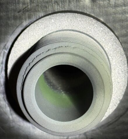
Figure 2. Chromium deposits / discoloration in the area of a graphite cooling nozzle | Source: The HERRING Group, Inc
For example, stainless steels, tool steels, and more exotic alloys run in a vacuum furnace will benefit substantially from the use of partial pressure atmospheres. In most heat treat shops, partial pressure cycles begin around 760°C (1400°F) at pressure from 1–1.5 Torr (1000–1500 microns). This is primarily because chromium present in many of these materials and in our baskets/fixtures evaporates noticeably at temperatures and pressures within normal heat treatment ranges. At around 990°C (1800°F), chromium will vaporize rapidly as a function of both vacuum level and time. In general, the practical operating vacuum level for most materials is significantly above their equilibrium vapor pressures. It is also helpful at times to know the temperature at which individual elements exceed a critical (10⁻⁶ g/cm²-s) vaporization rate (Herring 2015).
In practice, heat treaters often observe greenish discoloration (chromium oxide) on the interior of their vacuum furnaces (Figure 2), the result of chromium vapor reacting with air leaking into the hot zone. Otherwise, the evaporation deposit is bright and mirror-like. To avoid these types of deposits contaminating both the furnace and the parts run in it, an operating partial pressure between 1 Torr and 5 Torr (1,000 microns to 5,000 microns) is typical for parts that will boil away their elemental constituents.
Chromium Coloration
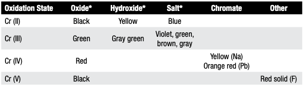
Heat treaters should be aware that although the most common color of chromium discoloration is green, the color is dependent on chromium’s oxidation state (Table B). For example, Cr (II) compounds typically appear blue, Cr (III) compounds appear green, and Cr (VI) compounds appear orange or red.
Notes: * Most commonly observed colors Table B. Oxidation Colors of Chromium and Chromium Compounds
Table B provides a more detailed breakdown of chromium’s oxidation states and associated colors.
Which Partial Pressure Gas(es) Can We Use?
Argon, nitrogen, and hydrogen are the most common partial pressure gases. Often, argon is preferred as it is a truly inert gas and tends to “sweep” the hot zone; that is, being a heavier molecule, it tends to reduce evaporation compared with nitrogen or hydrogen. Specialized applications, such as those in the electronics industry, may use helium or even neon (if an ionizing gas is needed). Gases having a minimum purity of 99.99% and a dew point of -60°C (-76°F) or lower should be specified.
Certain cautions are in order. For example, nitrogen may react with certain stainless steels and titanium bearing alloys resulting in surface nitriding. In the case of hydrogen, the normally near neutral vacuum atmosphere can be sharply shifted to a reducing atmosphere to prevent oxidation of sensitive process work or for furnace/fixture bakeout/cleanup cycles. Embrittlement by hydrogen is a concern for certain materials (e.g., Ti, Ta).
Figure 3. 410 stainless steel housings, hydrogen partial pressure (1,000 microns) at 1010°C (1850°F) | Source: Courtesy of Vac-Aero International, IncFigure 4. Knee implants (cobalt-chromium-molybdenum alloy) vacuum heat treated under an argon partial pressure at 1 Torr (1,000 microns) to prevent elemental evaporation | Source: Courtesy of Vac-Aero International, Inc
In Summary
Partial pressure atmospheres are required in many heat treating and brazing operations to achieve desired results. Introduction of the partial pressure gas into the furnace hot zone at one or more locations and controlling the partial pressure injection gas stream as a continuous flow, rather than trying to operate at a specific pressure, are critical considerations. The choice of partial pressure gas is also important both from a cost and quality standpoint.
References
Herring, Daniel H. 2014. Vacuum Heat Treatment. Vol. 1. Troy, MI: BNP Media.
Herring, Daniel H. 2015. Vacuum Heat Treatment. Vol. 2. Troy, MI: BNP Media.
Houghton, R., Jr. n.d. Private correspondence, Spectrum Thermal Processing.
Jones, W. R. 1997. “Partial Pressure Vacuum Processing – Part I and II.” Industrial Heating, September/October.
Jones, William. n.d. Private correspondence, Solar Atmospheres Inc.
Fabian, R., ed. 1993. Vacuum Technology: Practical Heat Treating and Brazing. Materials Park, OH: ASM International.
The Boeing Company. n.d. “Practical Vacuum Systems Design Course.”
About the Author
Dan Herring “The Heat Treat Doctor” The HERRING GROUP, Inc.
Dan Herring has been in the industry for over 50 years and has gained vast experience in fields that include materials science, engineering, metallurgy, new product research, and many other areas. He is the author of six books and over 700 technical articles.
In this Technical Tuesday installment, Neil Owen, general manager at Stresstech Inc., examines how BNA is redefining process verification across multiple industries by making quality control both traceable and measurable.
Heat treatment plays a crucial role in achieving the mechanical strength, fatigue resistance, and dimensional stability demanded of ferromagnetic steel components used in automotive, aerospace, energy, and heavy manufacturing sectors. From furnace batch carburizing to localized induction hardening, these processes are designed to produce precise microstructural transformations and stress distributions. Barkhausen Noise Analysis (BNA) has emerged as an effective method to confirm that these transformations have occurred uniformly across all parts and also detect subtle localized deviations.
Introduction
Verifying uniform microstructural transformations and stress distributions during critical heat treatment processes remains a challenge for quality control teams. Traditional verification methods, such as hardness testing, microstructural sectioning, and metallographic examination, are accurate but slow, invasive, and limited to a small area. Non-destructive alternatives, like eddy current or ultrasonic testing, provide some insight but often lack the sensitivity to microstructural and stress variations that accompany phase transformations. As manufacturers seek faster, data-driven approaches to verify furnace and surface heat treatment quality, Barkhausen Noise Analysis (BNA) has emerged as a highly sensitive and efficient solution.
BNA offers a non-destructive, microstructure-responsive means of assessing heat treatment performance, directly reflecting the metallurgical state of ferromagnetic materials. Its unique advantage lies in its sensitivity to both magnetic domain behavior and residual stress, which are influenced by the phase composition, hardness, and internal stress of the steel. This makes it an ideal verification tool for confirming that intended transformations — particularly the shift from softer ferritic or pearlitic microstructures to harder martensitic or bainitic phases — have occurred fully and uniformly.
The Barkhausen Noise Phenomenon
When a ferromagnetic material is subjected to a varying magnetic field, its magnetic domains (i.e., regions within the crystal lattice where magnetic moments are aligned) reorient in discrete jumps rather than continuously. Each jump releases a small electromagnetic pulse known as Barkhausen noise. The cumulative signal, measured as a function of applied field strength, provides a distinct magnetic “fingerprint” of the material’s condition.
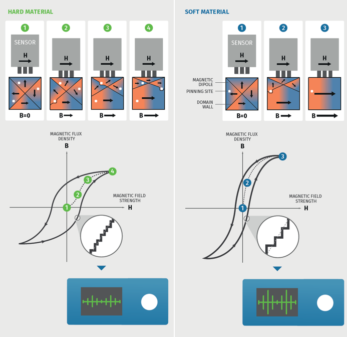
Figure 1. Visual comparison of how the magnetic domain reorients in discrete jumps within hard vs. soft ferromagnetic material Source: Stresstech Inc.
Hardness is related to the number of pinning sites (e.g., dislocations, precipitations, or other irregularities) in a material. When a magnetic field is applied to a ferromagnetic material, magnetic domain walls start to move. Domain walls collide with pinning sites in the material structure which impedes the domain wall movement. Magnetic domain walls move more easily in soft materials than in hard materials. Since hard materials contain numerous pinning sites, domain wall movements are more restricted. In soft materials, domain walls can make bigger jumps.
Because these parameters directly reflect the results of heat treatment, BNA provides a sensitive, immediate, and quantifiable indicator of metallurgical condition. When steel transforms from a soft ferritic–pearlitic structure to a hard martensitic one, the Barkhausen signal typically decreases by a factor of four to five, providing a clear signature of successful transformation.
Responsiveness to Microstructural Transformation
BNA is especially valuable because it responds directly to the magnetic consequences of metallurgical change. In untransformed ferritic–pearlitic steel, magnetic domains move freely, generating strong Barkhausen activity. As the microstructure transforms to martensite or bainite during quenching, domain wall motion becomes constrained by high dislocation density and lattice distortion, resulting in a lower, sharper Barkhausen response.
This distinct contrast enables this analysis to serve as both a quick verification tool and a diagnostic method. A simple contact check using a handheld probe can confirm within seconds whether a part or batch has achieved the target hardness and transformation state. Alternatively, an automated scanning or mapping inspection can reveal subtle variations caused by uneven heating, quenching, or post-process re-tempering and grinding.
Unlike many other non-destructive techniques, it requires no special surface preparation or coupling media. Measurements can be made directly on machined or ground surfaces, provided they are ferromagnetic and accessible. In some cases, BNA can also operate through coatings, such as HVOF chromium coatings on structural steel, and provide accurate insights. This makes it ideal for in-process verification, final inspection, and field assessments, supporting real-time process control and fast decision-making.
Comparison with Adjacent Verification Methods
While no single inspection method captures every variable, BNA occupies a distinctive position in the non-destructive testing landscape. Hardness testing provides a direct mechanical measure of strength but is destructive and slow. Eddy current techniques are fast but primarily respond to surface conductivity and hardness, not underlying microstructure. Ultrasonic methods are excellent for detecting internal flaws but less effective in distinguishing between tempered and hardened phases. X-ray diffraction remains the reference standard for residual stress measurement but is stationary, slower, and typically limited to laboratory use.
BNA bridges these gaps by offering metallurgical sensitivity, speed, and portability, making it an ideal complement to conventional hardness and microstructure testing and providing immediate feedback without sectioning or preparation. Several defining attributes are as follows:
Fast — each measurement takes only seconds
Non-destructive — contact-based, leaving no surface mark
Microstructure-sensitive — reflects both phase transformation and stress state
Portable and adaptable — usable in-line or in the field with handheld or robotic probes
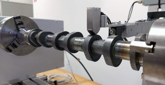
Case Example 1: Induction-Hardened Camshaft Inspection for Heat Treatment Defects
Camshafts undergo highly localized induction hardening to create a wear-resistant surface layer while maintaining ductility in the core. Variations in induction power, cleanliness from machining waste, coil positioning, or quench delay can lead to soft spots or over-tempered areas, which reduce fatigue life. Similarly, aggressive post-hardening grinding can cause thermal rehardening or burn damage, both of which affect local stress and hardness.
Figure 2. Sensor on camshaft Source: Stresstech Inc.
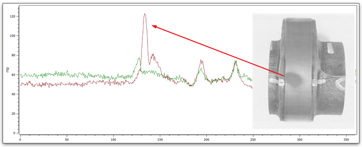
BNA provides a fast, non-destructive way to detect these variations. In one case, a powertrain manufacturer applied a line scan across each cam lobe using an automated BNA system. The resulting Barkhausen map revealed both high-signal areas (softer, grinding burned, re-tempered zones) and low-signal regions (hardened/normal zones).
Subsequent correlation with microhardness profiles confirmed that regions with elevated Barkhausen activity corresponded to localized softening due to heat treatment defects or rehardening from grinding burn damage, while areas with reduced response aligned to the master part readings that verify successful production of parts. This dual sensitivity allowed engineers to distinguish between heat treatment and surface finishing issues using a single technique.
Figure 3. Graphical Barkausen response showing heat treatment defect (soft spot) on cam lobe (etched lobe shown) Source: Stresstech Inc.
After integrating BNA into the inspection cell, the manufacturer reduced scrap and rework rates by over 25% through optimizing their production process based on resulting data, while gaining digital traceability for each camshaft. Automated result logging allowed process engineers to correlate defects with specific machine parameters, improving control and accountability across both induction and grinding stages.
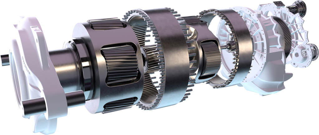
Case Example 2: Detecting Manufacturing Defects in Heat Treated Wind Turbine Gearbox components
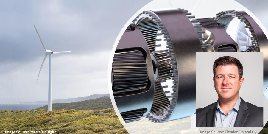
Flender Finland Oy (Flender), an expert in wind turbine gearbox manufacturing, has been in the industry for 40 years and is passionate about innovating gearbox solutions that enable cost-savings & trouble-free operation. Over the past 30 years, starting from the very first Barkhausen system to the latest robotized system, Flender has trusted their grinding inspection to Barkhausen noise measurement systems.
Figure 4. Flender Exceed Evo+ Source: Flender Finland Oy
Nowadays, wind turbine manufacturers require that surfaces of heat treated gears are also tested for the possibility of grinding burn. Grinding burn is a common name for thermal damages that occur on the surface during grinding processes following heat treatment. These burns cause local discolorations on the surface, and they can soften or harden surface layers and cause unwanted residual stress.
Nowadays, wind turbine manufacturers require that surfaces of heat treated gears are also tested for the possibility of grinding burn. Grinding burn is a common name for thermal damages that occur on the surface during grinding processes following heat treatment. These burns cause local discolorations on the surface, and they can soften or harden surface layers and cause unwanted residual stress.
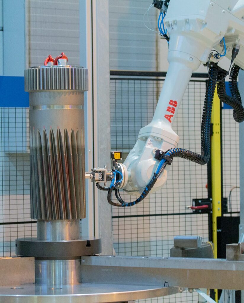
Figure 5. RoboScan XL measuring a sun pinion Source: Stresstech Inc.
Flender is an advanced BNA user and uses it beyond just sorting good samples to burnt ones.
Taisto Kymäläinen, quality manager at Flender, explains that Barkhausen’s method allows for the early detection of damage, as BNA reacts in the smallest changes in a microstructure. As a result, it can be used to optimize a grinding process to find correct grinding parameters. For example, BNA can reveal flaws in cooling or grinding stone wear before actual burn appears.
This means that with critical energy applications, BNA can be relied upon as a complete non-destructive testing technique when looking at microstructure consistency and integrity.
As BNA can identify consistent and accurate heat treatment characteristics of components, as well as additional damage caused during the manufacturing process, it is often relied upon as a crucial quality control check to verify each component in critical applications. Since BNA is a comparative method, users need to determine acceptable levels for their products with the master sample procedure. The master sample procedure can be validated with X-ray diffraction measurements or nital etching, for example. When the master sample procedure is set, BNA is an accurate method to detect microstructure changes.
This method has now become widely utilized by the energy sector as an established testing method, which is gaining widespread adoption by OEMs and operators as the gold standard of quality control inspections of critical components across their technologies.
Integration into Quality Systems
Modern Barkhausen measurement platforms combine precise sensing with digital analysis, providing traceable, repeatable, and operator-independent quality data. Results can be stored locally or integrated into manufacturing execution systems (MES) and quality management systems (QMS) for statistical process control and long-term trending.
Because of its portability and speed, BNA supports a range of industrial inspection strategies:
In-process verification of heat treated batches or ground components
Incoming inspection of hardened parts from suppliers
Failure analysis and field verification during maintenance and overhaul
When used alongside hardness or residual stress testing, this inspection technique enriches process understanding by revealing how microstructure, hardness, and stress interact. It transforms heat treatment verification from a subjective evaluation into a quantitative, magnetic-domain-based diagnostic of material integrity.
Conclusion
BNA provides a unique combination of speed, non-destructiveness, and metallurgical sensitivity for verifying heat treatment performance in ferromagnetic steels. Its fundamental sensitivity to magnetic domain wall mobility allows it to distinguish between soft, untransformed ferritic–pearlitic structures (high signal) and hard, fully transformed martensitic or bainitic phases (low signal).
For furnace batch processes, this technique delivers rapid confirmation that complete transformation has occurred and that quenching uniformity has been achieved. For localized induction-hardened or ground components, it identifies heat treatment defects, soft spots, and grinding-related damage in a single inspection.
As manufacturers pursue smarter, faster, and more traceable quality control systems, BNA is a practical bridge between metallurgical science and modern production efficiency, providing a magnetic fingerprint that reveals the true structural and stress condition of steel components.
About The Author:
Neil Owen, General Manager, Stresstech Inc.
Neil Owen serves as the general manager of Stresstech Inc. (Americas), based in Pittsburgh, PA. He helps manufacturers and researchers apply Barkhausen Noise Analysis and X-ray diffraction for heat treatment verification and quality control. With hands-on and leadership experience, he bridges advanced NDT with production needs in aerospace, automotive, and related critical sectors across the Americas.
For more information: Contact Neil at Neil.Owen@stresstech.com or LinkedIn.
Ask The Heat Treat Doctor® has returned to bring sage advice to Heat Treat Today readers and to answer your questions about heat treating, brazing, sintering, and other types of thermal treatments as well as questions on metallurgy, equipment, and process-related issues.
This informative piece was first released in Heat Treat Today’sNovember 2025 Annual Vacuum Heat Treating print edition.
Case depth, case uniformity, and final mechanical (as well as other) properties rely not only on controlling both equipment and process variability during heat treatment, but on having clean, properly prepared part surfaces prior to and during heat treating. Expert Dan Herring encourages to learn more below.
Case hardening is a thermochemical surface treatment process designed to add a particular element or combination of elements to a material such as steel. Familiar examples include carbon (carburizing); carbon and nitrogen (carbonitriding); boron (boriding); nitrogen (nitriding); and nitrogen and carbon (nitrocarburizing — ferritic or austenitic). These processes are typically designed to increase the near surface hardness of steel after quenching.
However, various problems can arise due to either the materials or the manufacturing methods employed prior to or during heat treating that will retard or prevent absorption and/or diffusion of the desired element(s) during heat treating. Some of the metallurgical consequences can include:
Shallow or uneven case depths
Surface oxidation
Intergranular oxidation or decarburization
High levels of retained austenite
Soft spots due to incomplete hardening
Machine-Induced Surface Conditions
Improper machining prior to case hardening can compromise surface integrity. Tooling choices, improperly maintained equipment, inadequate operator training, and even environmental factors can contribute to a variety of issues.
While machining problems occur frequently, they are mostly preventable. Attention to part surface condition, cleanliness, and mechanical integrity is essential before heat treating. Training, standardizing machining protocols, planned preventative maintenance programs, and part inspection prior to heat treating will help avoid these issues. Consult Table A for further details on how the causes and effects of undesirable machine-induced surface conditions can be solved.
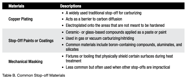
Splatter of Stop-off Paints on Unintended Areas
A material that masks the surface of steel and delays or prevents case hardening is called a stop-off or maskant. These materials are applied to specific areas of a steel part to prevent the diffusion of hardening elements (like carbon or nitrogen) into the surface during case hardening processes, such as carburizing, nitriding, or carbonitriding. (See Table B.)
Enriching Gas Additions (Sooting)
During the carburizing or carbonitriding process, it is not uncommon to develop a layer of soot on the surface of the parts, especially if the enriching gas additions begin before the entire load is uniformly up to temperature. In some instances, the amount of soot formation is such that the case depth or uniformity is affected. This is often difficult to diagnose, as the soot layer “washes off” during quenching in a liquid, and the part surfaces come out of the furnace looking reasonably clean.
Material-Related Issues
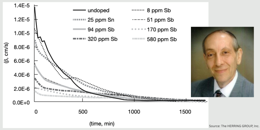
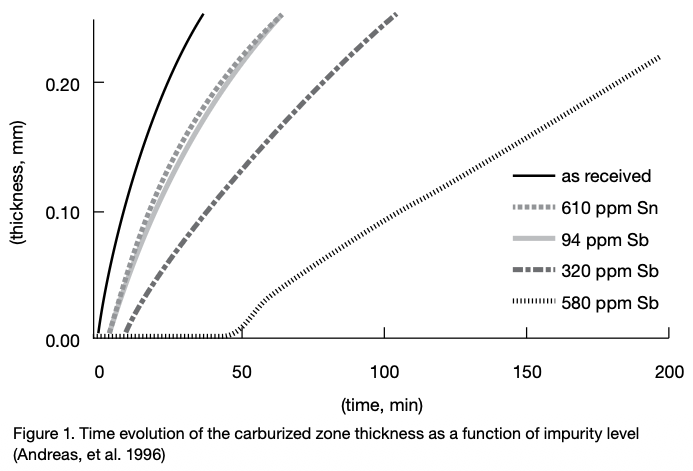
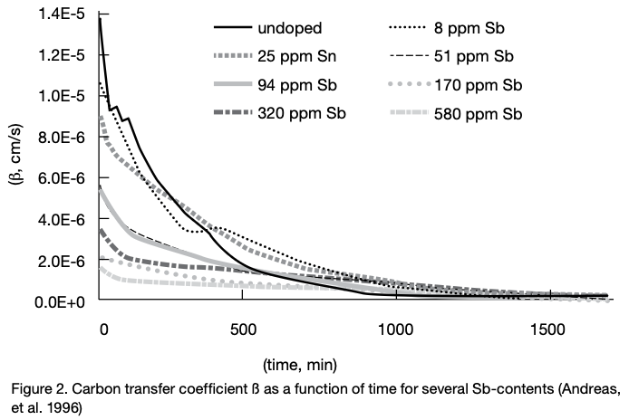
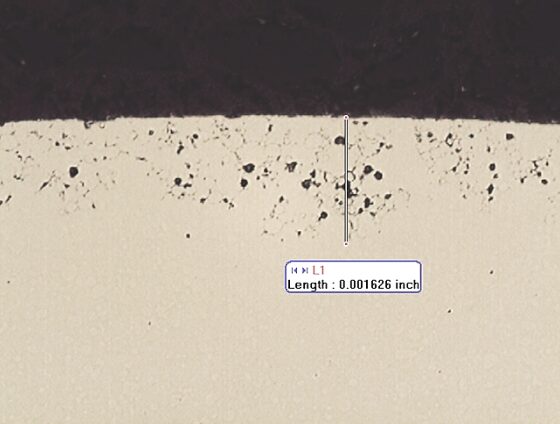
The use of scrap in steelmaking, especially for low alloy case hardening steels can lead to a relatively high level of impurities and tramp elements. At high temperatures these impurities tend to segregate at grain boundaries and migrate toward the surface. This type of segregation can retard case hardening by impeding element (e.g., carbon) transfer. For example, the effects of tin (Sn) and antimony (Sb) on the kinetics of carburization are particularly problematic (Figure 1).
The effect of tramp elements on retardation of carburization can be expressed in the following order (Andreas, et al. 1996), namely Sb > Sn > P > Cu > Pb. To see the effect of one such element, the carbon transfer coefficient (ß) for typical commercial steels is shown as a function of antimony (Sb) content (Figure 2).
In Summary
These are a few of the many causes delaying or preventing case hardening from being effective. There are many others, including alkaline cleaning compounds (in too high a concentration) and even phosphate and other drawing lubricants used in the manufacture of fasteners. Inspection and cleaning of the part surface prior to case hardening will avoid many of these issues. Reviewing material certification sheets for elements known to interfere with case hardening is also an effective way to anticipate problems with case hardening.
References
Herring, Daniel H. 2014. Atmosphere Heat Treatment, Volume 1. Troy, MI: BNP Media.
Herring, Daniel H. 2015. Atmosphere Heat Treatment, Volume 2. Troy, MI: BNP Media.
Ruck, Andreas, Monceau, Daniel, and Grabke, Hans Jürgen. 1996. “Effects of Tramp Elements Cu, P, Pb, Sb, and Sn on the Kinetics of Carburization of Case Hardened Steels.” Steel Research 67 (6): 242–48.
About the Author
Dan Herring “The Heat Treat Doctor” The HERRING GROUP, Inc.
Dan Herring has been in the industry for over 50 years and has gained vast experience in fields that include materials science, engineering, metallurgy, new product research, and many other areas. He is the author of six books and over 700 technical articles.
In this episode of Heat TreatRadio, host Doug Glenn invites Dennis Beauchesne of ECM USA to explore the technology, benefits, scalability, and sustainability of modular heat treating systems. Together, they discuss how shared utilities, automated transfers, and adaptable heating cells can replace multiple standalone furnaces without compromising quality or precision. Learn how these systems streamline and simplify operations for future expansion — one cell at a time.
Below, you can watch the video, listen to the podcast by clicking on the audio play button, or read an edited transcript.
The following transcript has been edited for your reading enjoyment.
Introduction
Doug Glenn: I am very privileged to have with me today, Dennis Beauchesne from ECM USA. We’re going to be talking about modular heat treating systems, which is a growing category of equipment.
ECM Synergy Center (00:50)
Doug Glenn: Tell me about ECM’s Synergy Center, which is where you are at right now, on the shop floor.
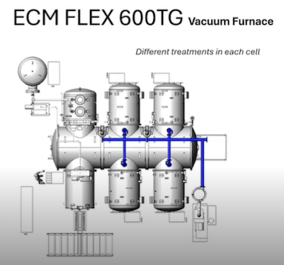
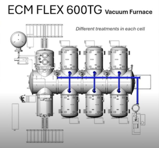
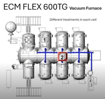
The ECM Flex 600TG vacuum furnace located in the ECM Synergy Center Source: ECM USA
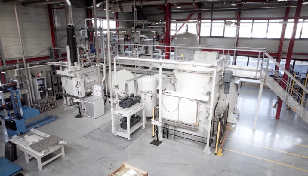
Dennis Beauchesne: I’m standing here in the middle of our Synergy Center. It’s about a 5,000-square-foot facility that is dedicated to proving out client parts for testing various processes, mostly LPC, but we also do a number of other processes here. We have a full metallurgical lab, 3D microscope, a number of tools, including a CMM that we can do before and after heat treat distortion testing for clients that want to know how much their parts move.
It’s a dedicated center just for clients to use. We also use the center for pre-completion of installations, final testing, and training, such as training on maintenance, understanding the software, and how everything works together.
Doug Glenn: It’s proof of process plus much more — helping clients’ proof of process.
Dennis Beauchesne: Absolutely. That’s a big part of convincing people that this process is for them and that it works on their part. We can send them ten different reports of an exact same material and part, but they want to know what their part will do.
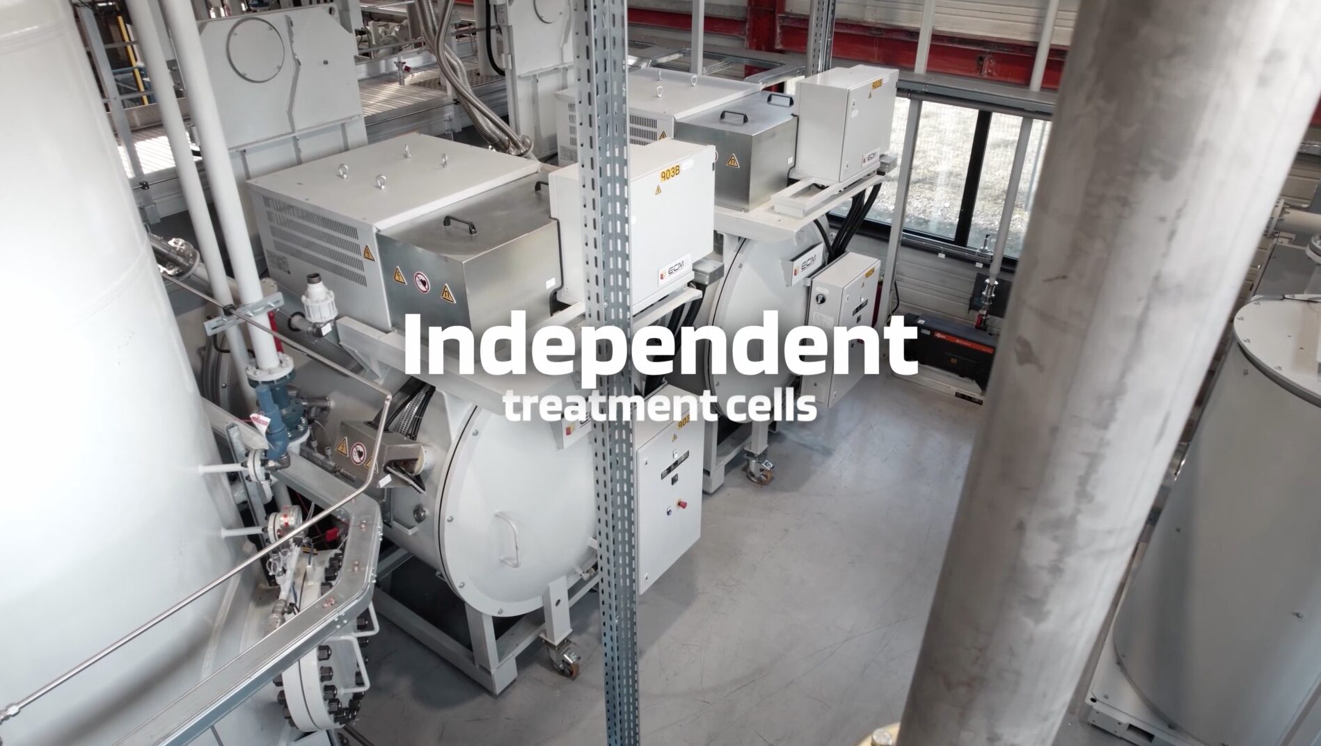
What is Modular Heat Treating? (02:50)
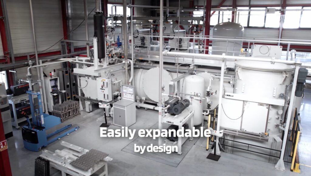
Doug Glenn: On a very basic, rudimentary level, what is modular heat treating and how does it differ from what might be considered standard or normal heat treating?
Dennis Beauchesne: A modular heat treat system is one that works together to have more than one furnace working in the same platform. You may have a shop that has five or six vacuum furnaces separated — they each have their own door, vacuum system, electrical supply, quench motors…those types of components. Or you may have a series of batch IQ furnaces for carburizing; those systems are one off, which means they are individual, independent systems.
In a modular system, you try to utilize those facilities for the use of multiple heating chambers. Instead of having one vacuum furnace with one set of pumps and one gas quench motor, what we would do is have three to eight heating cells that would be utilizing one quench, depending on the process timing; that’s all done with an internal transfer car and we try to utilize one vacuum system. It’s much smaller than what you would have for three, four, or even eight cells.
If you had oil or high pressure gas quenching, which is what’s dominating right now in the modular heat treat business, you could supply basically six batch IQ hot zones to one oil quench.
The savings then are huge simply by removing five or six other quench tanks in front of this system, as well as leveraging the floor space (and the number of pits you have to dig). Other advantages including utility savings and utilizing equipment across a number of heating chambers.
Doug Glenn: This modular approach is basically separate chambers that are dedicated to doing whatever that chamber is doing, and they are all in some way interconnected. For standard units, you would heat up, pre-process, do the actual process itself, cool down, all in the same chamber. In a modular unit, you move from chamber to chamber to do each of those separate steps.
Dennis Beauchesne: Yes, I refer to it as a continuous batch.
Doug Glenn: Continuous batch. We were talking before we actually hit the record button with your colleague there, Allison DeAngelo, who just got done visiting the Heat Treat Boot Camp. We were talking about different types of furnaces, and we started talking about continuous vacuum, which of course, is almost a misnomer — a vacuum can’t be continuous because you have to open it up and break the vacuum to get stuff out. Anyhow, we talked about it basically being a batch, right? A batch furnace that’s continuous, a continuous batch furnace.
Benefits of Modular Heat Treating (06:35)
Now that we have a basic understanding of what these modular systems are, why would companies want to move from the standard type of heat treating system to a modular system?
Dennis Beauchesne: Manpower. If you are running five or six vacuum furnaces, you are going to need a number of people to open the doors, put new loads in, those kinds of tasks. With a modular system, you only have one entry or one exit area. Therefore, you are only going to load once every 15-20 minutes, and the system is going to take over and control that load going through the system.
In addition, especially in a carburizing atmosphere situation, you can have every load be a different case depth — a different process in each cell — and then the next load that goes in that same cell can be totally different from the one before. For instance, if you had a batch IQ, you typically use the same carbon potential, and you are typically going to run the next load almost identical to the one before. In contrast, with the modular system, each cell can run a different process every load.
It’s also easier to integrate automation if you are doing capacity increases.
Throughput Comparison (08:00)
Doug Glenn: What is the comparison of throughput between a standard unit and a modular unit?
Dennis Beauchesne: The throughput comparison is interesting because you typically can use a little higher temperature for a carburizing and a little higher carbon potential, and of course that’s what we specialize in here with the modular systems. You can achieve about a 30-40% gain in your cycle time. That furnace is operating very close to 100% occupancy, because when that load is done, you are moving it out right into the gas quench. Then, the next load comes and goes right into it.
Doug Glenn: You are able to increase your throughput because you have basically 100% utilization of the equipment or very close to that. Comparatively, you don’t necessarily have that in the standard equipment.
Product Quality Comparison (09:15)
Doug Glenn: Do modular systems produce higher quality products?
Dennis Beauchesne: The quality of the parts coming out of the system is improved. A vacuum environment is a very clean environment, especially if we are considering atmosphere and low pressure carburizing — it’s in a vacuum. We typically do everything in high pressure gas quenching. However, even in oil quenching under vacuum, you are going to have a much cleaner part.
Also in low pressure carburizing, the carburizing is much more uniform throughout the part because we heat it to temperature under nitrogen before the part gets to austenitizing temperature to start attracting carbon. We make sure that the full part, that’s the tooth, the root, every piece of the part, is at temperature before we start adding carbon to the load, which makes a more uniform case depth, and therefore makes a stronger part.
Doug Glenn: Since each module, each chamber, is dedicated to doing what it is supposed to do, it seems like the consistency and the reliability of the parts being processed in a modular system have a much better chance of being higher quality.
Dennis Beauchesne: You do not have six different variable chambers or six different variable systems. You just have to look at monitoring the connection between those and understanding that the vacuum levels are all the same across the levels and across the cells. Each cell can meet a different temperature and run a different process, but those are consistent across the board.
Typical Dedicated Cells/Chambers (11:10)
Doug Glenn: What would be the typical dedicated cells/chambers of a modular system?
Dennis Beauchesne: It is dependent on the processes. They are most widely used for vacuum carburizing. For pre-oxidation and preheating, we usually use an air oven outside of the system, and we connect that with an external loader. Before the load goes into the modular system, the load will go through a regular air oven, be heated to around 700°F (400°C), and then the load will be moved in.
For sintering and those kinds of applications, there is a debind step or a preheat step that would be done in one cell. Some of the processes that can be done in a modular system include:
Low pressure carburizing
Low pressure carbon nitriding (LPC)
FNC (ferritic nitrocarburizing)
Nitriding
Debinding
Sintering
Neutral hardening
The most prominent process right now is LPC, and that is being used all over the world in these systems.
Advantages of a Modular Unit for Captive Heat Treaters (12:53)
Doug Glenn: Why would a modular unit be beneficial for a captive heat treater, someone who does their own in-house heat treating, which probably means they’ve got potentially high volume, low variability as far as their workloads?
Dennis Beauchesne: The modular unit has many different advantages. First of all, floor space. You are going to save a lot of floor space by not having multiple furnaces set up separately. You will also save utilities because you would not have as many vacuum pumps or electrical systems running these furnaces on their own. You will have some shared service and utilities in that fashion.
Doug Glenn: That would also likely lead to maintenance cost savings as well, correct?
Dennis Beauchesne: Yes, it all goes down the line. Anything that you have multiples of, you are going to have much less costs than on a joint system. The modular system might be a little larger than one singular unit, but there will be fewer of them.
For vacuum carburizing applications in a captive shop, the quality and cleanliness of the part is very, very important. Gas quenching lends itself to no oil in your plant, no washers necessary for a post-quench. Typically, there’s a washer before the process starts, but you do not have to have any wash to get the oil off of the parts with a modular unit — you do not have to reclaim the oil or the water from the washer. You would not have waste oil in your plant either or any oil on your plant floor. These are some of the reasons some of the larger captive shops have gone to the modular systems.
Also, safety: There are no open flames with a modular unit, no risks of fire on the systems. They are also easier to maintain. For a fully operational, let’s say, eight-cell system for high production, captive operation, it would only take about five hours to cool that whole system down if you had to go in and work on the whole system. In comparison, it’s going to take you three to four days sometimes to cool down a typical atmosphere, high-temperature furnace.
It also takes time to heat the system up again. In a modular system, it takes about an hour and a half to heat the system up again and then you are ready to start running. That means now you can schedule your downtime on weekends or holidays. You do not have to have staff present to run anything.
You also do not have to have a secondary equipment, like Endo generators running to feed the carburizing gas. The carburizing gas is using acetylene out of cylinders, it’s not a regenerative system. You do not need a separate piece of equipment to feed to the furnace.
Another benefit is CapEx expansion. Typically, captive heat treaters do not want to buy everything upfront because their volumes are going to increase over time. In the beginning, they typically only need one or two cells ready to do a small amount of production so they can prove out the production and prove out the system. Then they can start building the system with more cells and more capacity later on. Generally, it’s two to three days of downtime to add a cell to a system. It’s very convenient to do that with a modular system. All of the utilities are typically alongside the modular system so that you can easily add those or add a cell to it over a short period of time, and those cells can be ordered a year or two down the road whenever you might need that.
You also can order peripheral equipment, like extra temper ovens or additional automation. You can add a robotics system to the layout as well. That’s why captive shops are very interested.
Finally, workforce: It’s a little bit easier to get someone to work on a modular system. These systems are completely clean and white. The one located in our Synergy Center has been there for eight years. We use it every single day, and it’s a very clean aesthetic environment for someone to work in. These systems are also water cooled, which means not a lot of extra heat in the building around you to work in.
Advantages of a Modular Unit for Commercial Heat Treaters (17:59)
Doug Glenn: What are some advantages of modular units for commercial heat treating?
Dennis Beauchesne: On the commercial heat treat side, modular units are typically useful because you can get multiple processes out of similar cells and you can have a system that has oil and a gas quench.
You can have a lot of flexibility in that one system that you have in the plant. I’ve visited hundreds of captive and commercial heat treaters. They generally have a number of furnaces in one area of the plant, and a number of furnaces in another area of the plant. A modular system gives you all the capability in one machine and one tool: oil quenching, gas quenching, FNC, nitriding low pressure, carburizing, carbonitriding, and neutral hardening all in one piece of equipment.
Automation and Robotics with Modular Heat Treating (18:57)
Doug Glenn: What automation and robotics advantages are there with modular systems?
Dennis Beauchesne: This is the new trend. People that have modular systems are now considering, “How do I automate the system to get more production out of it?” And what we’ve been doing the last five years especially is implementing systems that use CFC fixtures.
CFC fixtures are very robust in the furnace but sensitive to being controlled outside. Therefore, what we try to do is have the CFC fixtures be utilized in an automation that no humans have to interact with it. We usually use robots for external loaders and internal loaders to move the fixtures through the process.
This causes you to have a lighter load, which means less heating time, less energy being consumed. Also, the fixtures last three to four times longer if they’re not damaged. But of course, all of these systems can be using regular alloy steel as well, and we can fixture different parts. You can use baskets, we are now doing bulk loading where we have parts that are filled into baskets and then processed. We are doing that with vacuum carbonizing as well, not just neutral hardening.
So it’s really interesting to see how the limits are being pushed, as well as the different materials that we are gas quenching now. I know 20-25 years ago, we were quenching some simple materials that were very high hardenability, and today we’re quenching a lot of less hardenability steels.
Doug Glenn: Is that primarily due to increase of pressure in the quench?
Dennis Beauchesne: It’s pressure, it’s flow, it’s the intensity of the gas going through the parts. It’s also heat removal as well — heat exchangers, removing the heat out of the load faster. We also have reversing gas quench motors to reverse the flow inside from top to bottom, bottom to top, in the middle of the cycle.
Sustainability of Modular Heat Treating (22:24)
Doug Glenn: Do these systems promote sustainability and greenness?
Dennis Beauchesne: Absolutely, especially when it comes to carburizing. These systems have been compared against typical atmosphere carburizing cycles, and only about 4% of the carburizing time has gas injection, when we are actually injecting acetylene and having hydrocarbons being used in the process.
If you took the same cycle times, seven or eight hours of a carburizing cycle, you are flowing Endo gas or nitrogen methanol in the system for that full time. In contrast in a vacuum carburizing system, it’s 4-5% of the time of the cycle that you’re injecting into the furnace. Ultimately, you only have about 10% of the CO2 output that you would have in a typical atmosphere furnace.
As mentioned previously, there’s also no oil in your plant. You’re not reclaiming oil out of the water and the wash or off the floor or in your car when you leave your heat treat shop.
How Does the Modular Heat Treating System Work? (23:40)
Doug Glenn: Let’s talk through the process a little bit. You provided us with figures to aid in describing the process. We have included these. Describe how the system works.
Dennis Beauchesne: This animation is a plan view of one of our Flex systems. In the center, going left to right, is a tunnel section. This tunnel section is about an 8-foot diameter. It has an automated loader that moves down left to right or horizontally, and it transfers loads from each cell to another, in and out.
On the bottom left is a loading/unloading chamber. In that loading/unloading chamber, we remove the air once the load is put in there, and then we balance the vacuum on that cell to the tunnel’s vacuum. Then we’re capable of moving that load to an available heating cell, and that would be on the right of the system — on the top right or the bottom right of the tunnel, those are heating cells. Then recipe for that particular load will be loaded into that cell. While that load is processing, another load will be moving into the tunnel and into the other heating cell as well.
On the top left is the gas quench cell, which could be in this orientation or instead have an exit on the back as well. In this system, you could do neutral hardening, carbon nitriding, LPC, a number of the processes. This is a very valuable tool, especially in a commercial heat treat heat treat shop.
Doug Glenn: Is this whole unit, including all four chambers under vacuum? I noted there are separation doors on the purge and the entry chamber. Can this area be vacuum sealed?
Dennis Beauchesne: Yes. There are vacuum seals on the loading/unloading chamber on the bottom left and then the top left. The gas quench also has a seal from a pressure standpoint. The two heating chambers have a graphite door — we call it the flap door, and it just flaps and it doesn’t really seal actually against another face of graphite. It’s graphite-to-graphite. We pull vacuum out of there through the tunnel to create the central vacuum pressure in the system. We also pull vacuum from the cell itself, and we could also have a separate door on the front of the unit if the process necessitates that or if we feel that a door is needed there by a client.
In a normal state or a standard unit, there are no hot seals on the door, only vacuum seals on the loading/unloading chamber and the gas quench.
Doug Glenn: In the animation, your vacuum pumps are down in the bottom right, correct?
Dennis Beauchesne: Exactly, that’s a process pump.
Doug Glenn: What is located in the top left?
Dennis Beauchesne: On the top left, we have a gas quench tank. We want to ensure we have enough gas pressure and volume there to quench the load quickly. It’s very important to get the gas through the gas quench quickly.
ECM Flex 600TG vacuum furnace with two added heating cells / Source: ECM USA
Now, we have added two more additional heating cells and a central tunnel section. In essence, you just doubled the space, doubled the capacity of the unit, where you only added 50% of the space of what you had for capacity before.
We are still utilizing the same gas quench and the same loading/unloading cell. We only added utilities for the two heating cells, not for a whole gas quench or oil quench capability there; this can be added in a very short time.
Doug Glenn: Now I’m gonna go let this video roll here for a minute. There we go.
ECM Flex 600TG vacuum furnace with four added heating cells for six heating cells total
Dennis Beauchesne: So now we added another 50% capacity with two more heating cells (six heating cells total) and a tunnel section. Typically, what you want to do is to have the tunnel sized for about five years out for your capacity and then buy the cells as you need them and have it grow so then the tunnel is ready to implement.
We have just tripled the capacity of this installation, and we are only still using the same gas quench and the same loading/unloading cell. Generally, this system could go to eight cells and have just one gas quench, that’s our typical orientation.
Doug Glenn: It looks like we also added a discharge side here. Whereas before we were going in and out.
Dennis Beauchesne: Yes, this adds to the efficiency of the system because the load is already in the gas quench when it’s finishing, so it just exits out the back, out the door.
Doug Glenn: Now what do we have here?
ECM Flex 600TG vacuum furnace processing different treatments in each cell. See animation above to watch the animation in motion.
Dennis Beauchesne: We have the loads entering, and the loads will go to the first cell that is available (empty). Then that recipe would be downloaded for that cell, and then the next load will go to the next available heating cell and download that recipe into that cell. These could be two different loads.
One load could be for neutral hardening; one could be for carburizing. One could be for carburizing in a low case depth. The other one could be carburizing at a deeper case. In this case, we just see the gas quench on here, but this tunnel could also be outfitted with an oil quench as well, and you could have one load go into gas, quench one load, go into oil quench or both going to either.
Doug Glenn: This gives people a sense of what the process looks like.
Processes and Materials for the Modular System (30:29)
Doug Glenn: Are there any processes or materials that do not make sense to process them through one of these systems?
Dennis Beauchesne: If you are doing a lot of annealing and normalizing, those are longer cycles. There is some regulated cooling that occurs. This is not really the type of equipment investment that you would want to make for those processes. If you were going to use it for a few loads in your plant where you received parts that weren’t annealed or you wanted to try to anneal a part for a particular process before you went to full production, you could certainly use a modular system for that, but it’s not a cost effective methodology. Neither would we recommend preheating in the cell. However, it is very flexible for a number of other processes that we have mentioned.
The size of the part is also important to note. These systems are typically 24 inches wide and about 39 inches long and about 28 inches high. However, we will soon have a new system, the Flex Max, a 12-9-9 system. It’s a 36×48 unit that comes with an oil quench and is modular, like this. We can either do an oil quench or a slow cool cell on that system. So, we will have that capability of 36×48 in that modular system.
Other than that, restrictions on material? Very few there. Like I said, you would not want to do annealing and normalizing on a lot of parts, but you could do it in these units.
Doug Glenn: It sounds like the sweet spot is surface modification type applications, and some sintering is possible with dedicated chambers.
Dennis Beauchesne: Yes, sintering and brazing is also possible.
Doug Glenn: Does that include aluminum brazing?
Dennis Beauchesne: Not aluminum brazing, but some brazing applications.
Expenses with Modular Heat Treating Systems (33:03)
Doug Glenn: What would be considered capital expenses for this modular system?
Dennis Beauchesne: As far as capital expenses, it’s not a furnace-to-furnace comparison. Clients always ask how much our furnace is. But companies need to first take two steps back and take a look at their incoming material, how they would like to be able to modify that incoming material in their heat treat process to make sure that their outgoing quality is higher than it is today. That’s the kind of benefit that this type of modular system gives you — a better quality part, safety in your plant, and a better quality work environment with being able to turn the system off and not need additional personnel around.
These are all factors that have to be considered when thinking about the CapEx expenditure and investment. When we consider these factors, a modular system investment is a much better situation than looking at a furnace-to-furnace replacement, and that’s really the thought process that clients need to go through to understand the actual investment and value of the system.
Doug Glenn: What about the operational expenses?
Dennis Beauchesne: For instances, if you had a batch IQ sitting there, you would typically keep it running whether it has a load in it or not. With a modular system, you just shut off that cell that you’re not using. It does not take any more energy. If you are not working five days a week, you do not use it on the weekends — you shut it off. You do not use it during Christmas shutdown or any holiday shutdown, vacation shutdown. You’re able to shut it off and that means saving a lot of energy and labor by having it off.
Also, in the opposite way, you could run it lights out if you wanted, as well. You could stock up a number of loads on the automation before you leave, have the system operate it, run it, and have the load come back out before the morning. You could have it time start as well, if you wanted to start it on Monday at 5 AM, but you will not be there till 8 AM. You would come in and the furnace would be hot and ready to run a process.
There are a number of operational advances over the typical operational heat treat that’s out there today.
Doug Glenn: How does maintenance work with these systems? Say your heating element goes bad in cell number three, do I have to shut the whole system down to fix or can I fix number three and leave the rest of the system up and running?
Dennis Beauchesne: In this situation if you had a tunnel like we showed, you would typically shut off that cell; that is, if you knew that heating element was out or it wasn’t heating properly, you could shut off that cell, de-validate is what we call it, and then keep running the rest of the system until you had a window in your production that you could shut the whole system to get into that heating element.
If you had a system with doors on the front, it could be possible to go in the back while the system is operating. Then, it would be all based on your safety requirements for your plant and those kinds of things.
To do that, we have another system called the Jumbo, and it is much more flexible in the maintenance world. It has a vacuum car that moves down on rails and docks and mates with every heating cell on the system. In that line, the heating cell can actually be isolated from the rest of the line. You would just slide it back (It’s on wheels, it slides back about three feet away from the line), you put in a new piece of safety fence, and you continue to run your line. You can completely lock out/tag out that cell and work on it completely.
Doug Glenn: How would you approach a vacuum leak since the whole system is connected, right? I believe you mentioned these are graphite-on-graphite doors.
Dennis Beauchesne: You would want to fix the leak before you move on. Especially if it’s a bad leak. If it’s something that’s causing you to not maintain your process pressure, you certainly don’t want to do that, and that’s true with every vacuum piece of equipment.
ECM Modular Systems (38:55)
Doug Glenn: How many of these modular type systems does ECM have out in the marketplace?
Dennis Beauchesne: The Flex is the most popular modular system, which we discussed with the animation. We also have a number of Jumbos systems, and the unit in our Synergy Center is called a Nano, which has become more and more popular these days. The Nano has three different size chambers, but they’re typically smaller, 20x24x10 inch high size chamber. I explained a little bit about the Flex and the Jumbo is the same.
Out of those three systems, we have more than 350 modular systems, not just the heating cells, but more than 350 systems that are out in the marketplace today operating, running parts every day, running millions and millions of parts every week. Those systems are comprised of about 2,000 heating cells. As much as people hear about this being a new technology, it has actually been around about 30 years, and many companies have been using these systems and have replaced a number of pusher furnaces and those style furnaces for high-capacity installations especially.
Doug Glenn: Okay, that sounds good. I really appreciate your time.
About the Guest
Dennis Beauchesne General Manager ECM USA
Dennis Beauchesne joined ECM over 25 years ago and has since amassed extensive vacuum furnace technology experience with over 200 vacuum carburizing cells installed on high pressure gas quenching and oil quenching installations. Within the last 10 years, his expertise has expanded to include robotics and advanced automation with the heat treat industry high-demand for complete furnace system solutions. As General Manager of ECM USA, Dennis oversees customer supply, operations and metallurgical support for Canada, U.S., and Mexico for ECM Technologies. He has worked in the thermal transfer equipment supply industry for over 30 years.
Heat treatment impacts almost every facet of our lives, yet few people are aware of how important this practice is to a modern way of living. Heat treatment is a process which changes the microstructure of a metal, such as hardening, carburizing, tempering, and many others.
When a metal is formed, it undergoes heat treatment in order to make it longer lasting, change its structure so that it becomes harder or softer, or reduce the tendancy toward cracking which can form during manufacturing. To help us appreciate the impact of heat treatment on our daily lives, Tiffany Ward, daily editor for Heat Treat Today, has prepared this illustrative post.
Breakfast of Champions
You wake up in the morning and roll yourself out of bed, greeting a foggy sunrise through the window. You stumble to the kitchen to fire up your cast iron skillet.
Cast iron contains a minimum of 2% carbon
At one time, that same cast iron skillet lived a provincial life, known as simply: iron. Cast iron is made from iron with greater than 2% carbon, which is in the form of graphite. When that iron was “cast,” it was melted at a high temperature, and once cooled, it transformed into a very stable material that heats and cools uniformly. Perfect for your sunny-side-up eggs.
At the foundry, someone poured the molten metal into a mold to form the exact shape your pan is in today, and then it underwent numerous heat treat processes: annealing, normalizing, tempering, and even graphitizing (a process of converting carbon into graphite). The particular processes the skillet underwent depend upon the chemistry of the cast iron.
Almost all cast iron has carbon and nitrogen added to its surface in a process called ferritic nitrocarburizing plus post-oxidation. This heat treatment gives a shallow surface layer to the pan for better wear resistance. The skillet is heated up between around 1550°F and 1650°F inside a protective atmosphere of Endothermic gas. Endothermic gas is a generated heat treat atmosphere. It is made up of approximately 40% hydrogen, 40% nitrogen, and 20% carbon monoxide. The Endothermic gas is enriched with both a hydrocarbon gas (i.e., natural gas or propane) and ammonia so that carbon and nitrogen can be added to the iron.
There are a variety of different furnaces that can be used for ferritic nitrocarburizing. Box, pit, and tip-up furnaces are used due to their large capacity. For cast iron skillets, one common choice is the pit furnace — a cylindrical furnace typically located in the floor of a factory. Pit furnaces can hold a lot of heavyweight items, making them a good fit for the cookware now resting on your stove.
Figure Source: Herring, Daniel H., Atmosphere Heat Treatment Volume 1, BNP Media II, LLC, 2014.
You pull a knife out of your drawer and begin slicing an apple. The blade reflects a beam of sun from the window, but it isn’t your best knife. You’ve noticed that some of your knives are sharper and can resharpen more easily than others; this is because of the quality of the original material used and the heat treatment process employed in manufacturing the knife.
Perhaps the knife you chose to use today was made from high carbon steel such as 1095. The blade was heat treated using a process of hardening, quenching, and tempering. After the blade was formed, it entered a continuous mesh-belt furnace and was quenched in either oil (in the case of a 1095 steel), or in the case of stainless steel or tool steel, cooled in still air.
Source: Dan Herring, The HERRING GROUP, Inc.Figure: Batch integral-quench furnace system installation (courtesy of AFC-Holcroft). Dan Herring, The HERRING GROUP, Inc.
At the same time of hardening and quenching, the handle was joined to the blade in a process called brazing. The entire knife was heated up to an austenitizing temperature and rapidly cooled in the quenching process, giving it a particular hardness level.
The hardening process can be performed in a vacuum furnace or an atmosphere furnace. The atmosphere is typically nitrogen or, more commonly, a nitrogen/hydrogen mixture. Another option is nitrogen plus dissociated ammonia (dissociated ammonia is 75% hydrogen, 25% nitrogen).
A typical temperature for the heat treatment of high carbon 1095 steel knives is 1475ºF. Stainless steels are run at higher temperatures, typically in the range of 1800º/1950ºF and tool steels even higher, to around 2200ºF.
After breakfast you head to the bathroom. You are anxious to rid yourself of unshaven scruff, carefully running a razor over your face. The razor blades were hardened and tempered for sharpness, so that you get a smooth, clean shave.
Like knives, razor blades are hardened and are made of a medium to high carbon steel. Unlike knives, they are hardened in a continuous strip form. Envision all of your razor blades as a single, thin strip, run continuously through a furnace to heat and cool them. The blade is heated in a protective atmosphere as it runs through the furnace. On one end of the furnace is a reel that coils the strip and at the other end is an un-coiler.
Continuous style furnaces have alloy tubes inside of them that are very small in diameter, typically one inch, which run the entire length of the furnace. As the razor strip is run through the tube it is exposed to an atmosphere of nitrogen and hydrogen, typically with 3% hydrogen, to protect the razor blade surface from oxidation. Once heated, the blade enters cooling either by surrounding the tube with water or by blowing forced air on the tubes.
A process called tempering follows hardening and quenching. When you harden a material you make it stronger, but less ductile, so there is a concern that the razor blade might break. The tempering process improves ductility, removing some of the hardness but improving flexibility.
Dan Herring, The Heat Treat Doctor®, describes the balancing act this way: “On one end of the teeter totter, metallurgically, are strength properties and on the other side of the teeter-totter are ductility properties. It’s always a challenge to properly balance the teeter-totter. If you get the hardness too high, what happens to the ductility? It’s very low. As a result, the material is super hard but may crack easier. On the other hand, if ductility is too high, the material is super flexible so that it can bend like a branch of a tree in the wind, but it has little strength. You need a balance of strength and ductility in all heat treated products, which is accomplished in part by proper tempering.”
Our lives are touched by heat treatment at every turn. Highly technical processes play their role in the formation of even the most common household items. While heat treatment may seem to some a niche industry, its impact on everyday life is ubiquitous.
A special note of thanks to Dan Herring, The Heat Treat Doctor®, for his insights and contributions which informed this post.
The Heat Treat Doctor® has returned to offer sage advice to Heat Treat Today readers and to answer your questions about heat treating, brazing, sintering, and other types of thermal treatments as well as questions on metallurgy, equipment, and process-related issues.
Today’s Technical Tuesday is a pre-release foretaste of the great content you can find in Heat Treat Today’sJuly 2025 Super Brands print edition.
Heat treaters and metallurgists speak a language unique to our industry and it can be confusing at times; terms like intergranular oxidation (IGO) and intergranular attack (IGA) are good examples, as these terms are often (incorrectly) used interchangeably. While these two phenomena sound similar, they have distinct mechanisms, causes, and impacts on material properties. Expert Dan Herring explores them more below.
What is IGO?
Contact us with your Reader Feedback!
IGO is a process by which oxygen preferentially reacts with the metal surface at the grain boundaries, creating oxides (Figure 1). It is not uncommon, for example, to see IGO present after a hardening process run in an Endothermic or nitrogen/methanol atmosphere. As parts are heated to austenitizing temperature, oxygen present due to minute air leaks or produced during the various chemical reactions with the atmosphere results in IGO. The grain boundaries are highly susceptible to oxidation because these are areas where different crystallographic grains meet and are areas of high energy due to the atomic mismatch and disruption of the regular crystal lattice structure.
Figure 1. Intergranular oxidation (IGO) along the surface of a heat treated chromium steel component. 1000X – As Polished Source: The HERRING GROUP, Inc.
What is IGA?
Figure 2. Intergranular attack (IGA) along the surface of a martensitic steel component caused by excessive submersion time in a citric acid solution. 1000X – As Polished Source: The HERRING GROUP, Inc.
IGA, on the other hand, is a broader term that refers to a corrosion phenomenon (aka chemical attack) that specifically targets the grain boundaries of a material. Unlike IGO, intergranular attack (Figure 2) is not limited to oxidation reactions but encompasses a variety of forms of attack involving such things as the formation of precipitates, the dissolution of material at grain boundaries, or the creation of corrosion cracks. Common forms of IGA include stress corrosion cracking (SCC) or sensitization in stainless steel.
In stainless steels, IGA is often triggered by high-temperature environments, usually in the range of 840º – 1560ºF (450 – 850°C) where carbon reacts with chromium to form chromium carbides at the grain boundaries, thus reducing the material’s resistance to corrosion in localized regions. In other alloys, factors like pH, chloride concentration, and temperature can lead to IGA.
Both IGO and IGA weaken the material’s structural integrity or lead to embrittlement compromising the material’s integrity.
Effect on Material Properties
The main effect of intergranular oxidation is the degradation of the mechanical properties, particularly a reduction in both ductility and toughness. As oxidation progresses along the grain boundaries, the material tends to become brittle, which can lead to premature failure under certain types of stress or thermal cycling. IGO often appears visually as a uniform discoloration or thin oxide layer on the surface. Surface pitting is not typically observed.
By contrast, IGA often appears as visible cracks, pits, or localized regions where the metal has been attacked (along the grain boundaries). This leads to a reduction in mechanical strength and can lead to SCC under certain circumstances. IGA can severely compromise the integrity of the material, particularly in critical applications like pipelines, pressure vessels, and nuclear reactors.
Materials Involved
IGO is most commonly observed in steel, aluminum, titanium, and nickel-based alloys, not only during heat treatment but when exposed to oxidizing environments in high-temperature applications, which also result in degradation and loss of material strength and other properties.
IGA tends to be more prevalent in stainless steels, corrosion-resistant alloys, and aluminum alloys. It is especially noticeable in alloys that are susceptible to sensitization (where chromium carbides precipitate at grain boundaries), leading to localized corrosion and cracks. Alloys that form a passivating oxide layer can be more susceptible to IGA if that layer is disrupted.
Principal Concerns
The main concern with intergranular oxidation is material embrittlement, leading to reduced ductility and potential failure under mechanical stress, especially in high-temperature applications. It can also affect the integrity of critical components, such as those used in aerospace or power generation industries.
By contrast, the primary impact of intergranular attack is loss of material strength, leading to structural failure, often without any clear outward signs (e.g., under chloride-induced SCC). It is more likely to cause immediate failure or a dramatic loss in performance, especially in structures exposed to corrosive environments.
How to Detect IGO and IGA
IGO is typically detected by examining the material’s surface using optical or scanning electron microscopy (SEM). Non-destructive techniques, such as X-ray diffraction (XRD), can also be used.
IGA is usually detected through methods like microstructural examination, electrochemical testing, or failure analysis. Techniques, such as SEM or energy-dispersive X-ray spectroscopy (EDS), can be used to examine the grain boundary regions for signs of corrosion.
How to Avoid IGO and IGA
IGO can be avoided by one or more of the following:
Environmental control: Making sure the heat treat furnace has no leaks, reducing oxygen partial pressure or controlling the furnace atmosphere in high-temperature heat treat operations.
Alloy design: The use of materials with stable oxide-forming elements (e.g., chromium, titanium and aluminum) or alloys with high resistance to oxidation (e.g., nickel-based superalloys).
Temperature control: Maintaining lower process temperatures and shorter times where possible to prevent oxidation at the grain boundaries.
Coatings and surface treatments: Application of protective coatings, such as copper plating, post-heat treatment aluminizing, or chrome plating, to reduce oxygen interaction with the grain boundaries during service.
IGA can be avoided by one or more of the following:
Environmental control: Reducing exposure to aggressive chemicals (e.g., chloride ions) by maintaining proper pH levels or using inhibitors in post-cleaning processes.
Proper alloy selection: Selecting materials resistant to intergranular corrosion (e.g., low carbon “L” grades of stainless steel or alloys with improved grain boundary stability).
Heat treatment: Avoiding sensitization of stainless steel by proper heat treatment methods that prevent the formation of chromium carbides at grain boundaries.
Stress relief: Reducing the likelihood of stress corrosion cracking by managing internal stresses during manufacturing and in-service conditions.
Key Differences
The differences between these phenomena are summarized in Table 1.
Table 1. Key differences between IGO and IGA Source: The HERRING GROUP, Inc.
Summing Up
While both IGO and IGA involve attack at the grain boundaries, they differ in their mechanisms, causes, and effects. From a heat treater’s perspective, IGO most often results at high temperature in oxygen-bearing furnace atmospheres, while IGA often results from pre- or post-heat treatment processing (cleaning, passivation, plating, etc.). Proper material selection, furnace and environmental control, awareness of what can happen, and inspection for these effects are key to preventing them from occurring.
References
Roberge, Pierre R., Corrosion Engineering: Principles and Practice, Mc-Graw Hill LLC, 2008.
Stene, Einar S., Fundamentals of Corrosion: Mechanisms, Causes, and Monitoring.
Schweitzer, Philip A., Fundamentals of Corrosion: Mechanisms, Causes and Preventative Methods, CRC Press, 2009.
About the Author
Dan Herring “The Heat Treat Doctor” The HERRING GROUP, Inc.
Dan Herring has been in the industry for over 50 years and has gained vast experience in fields that include materials science, engineering, metallurgy, new product research, and many other areas. He is the author of six books and over 700 technical articles.