A distributor of data loggers, paperless recorders and data acquisition equipment recently supplied a surface treatment company with runtime data collection to continually monitor its salt bath production line.
CAS DataLoggers provided the industrial data logging solution to Northeast Coating Technologies (NCT) in Kennebunk, Maine. NCT is a surface treatment company specializing in Salt Bath Nitriding Melonite® Quench-Polish-Quench (QPQ), among other processes, to produce high-durability metal components including piston rods, axles and more. NCT is using CAS’s dataTaker DT80 Intelligent Data Logger to continually monitor its production Melonite® line, specifically the salt bath area, recording tank temperature from multiple thermocouples and using these readings to trend the run data.
The Melonite® QPQ process forms a nitrocarburized layer around components comprised of an outer compound layer (iron, nitrogen, carbon and oxygen compounds) and a diffusion layer underneath. Initially, the process preheats components to raise their surface temperature before they’re placed in a tank containing liquid Melonite® salt (MEL 1/TF 1 bath) to start the nitrocarburizing process. Alkali cyanate is the active constituent in the salt bath, and this step requires the temperature in the range of 896°F – 1166°F with a target temperature of 1076°F. The components react with the salt and start to diffuse nitrogen and carbon into the substrate.
After a preset period of 1-2 hours, the components have the proper compound layer thickness and case depth. After immersion in the salt bath, the components are placed in a cooling bath (AB 1 bath) maintained at 700°F – 800°F for oxidative treatment which forms a magnetite layer on the components to improve corrosion resistance.
Tank temperature is the parameter NCT needed to monitor and trend for each of its 3 Melonite® salt tanks and the AB 1 oxidizing bath tank. With this in mind, CAS DataLoggers provided the facility with a Series 3 dataTaker universal data logger to automate their data collection.
“The dataTaker’s software is internal so everything this application needs is there in the dataTaker unit itself,” said CAS DataLoggers Applications Specialist Bill Hoon. “Now they have the memory, the data trending capability, and the alarming feature. That’s why the DT80’s our workhorse.”
A nickel-based heat resistant alloy that is very strong, corrosion resistant, and can be used at temperatures between -422°F and 1300°F has recently been released by a German specialist in custom prototypes and low-volume production parts.
Inconel 718 and Maraging Steel 1.2709 will expand Protolabs’ list of Direct Metal Laser Sintering (DMLS) materials that make up a wide range of metals available for rapid prototyping and the manufacture of functional end-use parts with complex geometries.
The high-temperature strength of Inconel 718 is derived from its ability to create a thick, stable passivating oxide layer at high temperatures, protecting the material from further attack. Inconel, which has good tensile, fatigue, creep and rupture strength, is thus ideal for the aerospace and heavy industries–particularly, in the production of jet engines, rocket engine components, gas turbine parts, instrumentation parts, power and process parts and related equipment that are exposed to extreme environments.
Photo credit/caption: Protolabs/Inconel 718 is a superalloy used in the development of turbojet engines for aircraft, among a variety of other applications.
A major U.S. automaker recently announced plans to transform its Chicago manufacturing facility to expand capacity for the production of three new SUVs.
Ford Motor Company is investing $1 billion in Chicago Assembly and Stamping Plants, the company’s oldest continually-operated automobile manufacturing plant, to prepare for the Ford Explorer, Police Interceptor Utility and Lincoln Aviator.
Joe Hinrichs, president, Global Operations
With the Chicago investment, to begin in March and be completed later in the spring, Ford is building an all-new body shop and paint shop at Chicago Assembly and making major modifications to the final assembly area. At Chicago Stamping, the company is adding all-new stamping lines. Advanced manufacturing technologies at the plants include a collaborative robot with a camera that inspects electrical connections during the manufacturing process. In addition, several 3D printed tools will be installed to help employees build these vehicles with even higher quality for customers.
“We are proud to be America’s top producer of automobiles. Today, we are furthering our commitment to America with this billion dollar manufacturing investment in Chicago and 500 more good-paying jobs,” said Joe Hinrichs, president, Global Operations. “We reinvented the Explorer from the ground up, and this investment will further strengthen Ford’s SUV market leadership.”
Chicago Assembly, located on the city’s south side, is Ford’s longest continually operating vehicle assembly plant. The factory started producing the Model T in 1924 and was converted to war production during World War II.
Photo credit/caption: Ford/Jason Hoskins, Ford employee, learns to build the all-new 2020 Ford Explorer.
This is the second in a 4-part series by Dr. Steve Offley (“Dr. O”), Product Marketing Manager at PhoenixTM, on the technical challenges of monitoring low-pressure carburizing (LPC) furnaces. The previous article explained the LPC process and explored general monitoring needs and challenges. In this segment, Dr. O talks about the data logger and its monitoring capabilities.
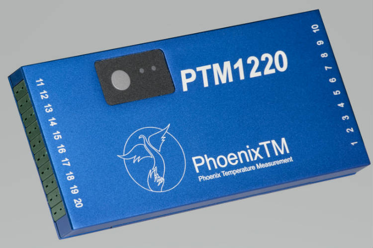
A data logger, an electronic device that records data over time or in relation to locatio, can be useful in a variety of configurations and modified to suit the specific demands of the process being monitored. A range of models are on the market. At PhoenixTM they include 6 to 20 channels with a variety of thermocouple options (types K, N, R, S, B) to suit measurement temperature and accuracy demands (AMS2750 & CQI-9). Provided with Bluetooth wireless connection for short-range localized download and reset (direct from within the barrier) the logger memory of 3.8M allows even the longest processes to be measured with the highest resolution to deliver the detail you need. An optional unique 2-way telemetry package offers live real-time logger control and process monitoring with the benefits detailed in a later section.
Live Radio Communication
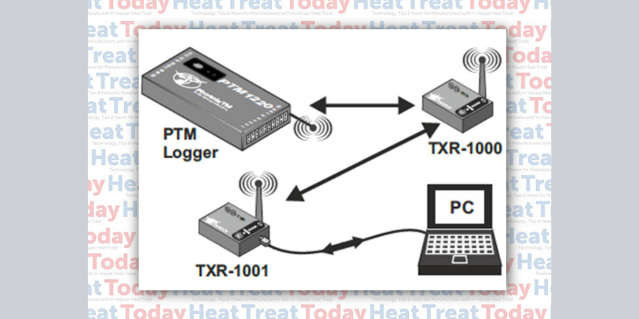
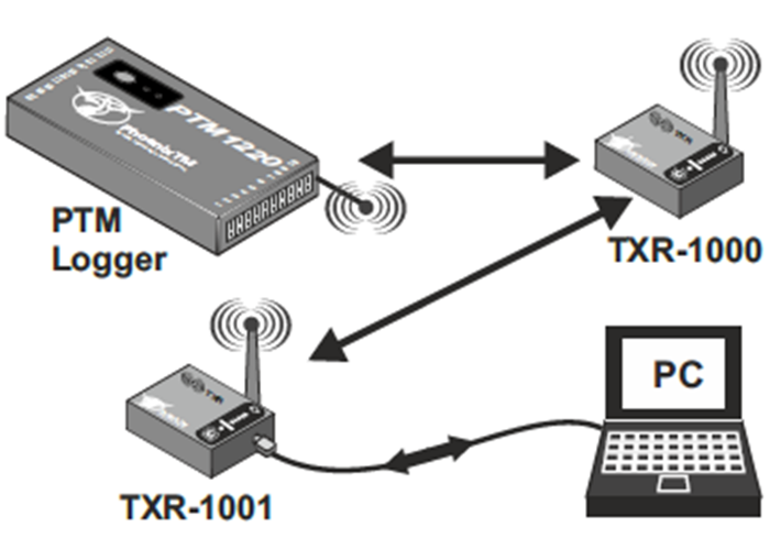
Figure 3: Schematic of RF telemetry real-time monitoring network
The logger is available with a unique 2-way RF system option allowing live monitoring of temperatures as the system travels through the carburizing processes. Furthermore, if necessary using the RF system it is possible to communicate with the logger, installed in the barrier, to reset/download at any point pre, during and post-run.
Provided with a high performance “Lwmesh” networking protocol the RF signal can be transmitted through a series of routers linked back to the main coordinator connected to the monitoring PC. The routers are located at convenient points in the process, positioned to maximize signal reception. Being wirelessly connected they eliminate the inconvenience of routing communication cables or providing external power as needed on other commercial RF systems.
In many processes, there will be locations where it is physically impossible to transmit a strong RF signal. In carburizing obviously within the oil quench, the RF signal is not capable of escaping when the system is submerged. With conventional systems, this results in process data gaps. For the PhoenixTM system, this is prevented using a unique fully automatic ‘catch up’ feature. Any data that is missed will be sent when the RF signal is re-established post-quench guaranteeing in most applications 100% thru-process data review.
Thru-Process Data Analysis and Temperature Uniformity Surveys (TUS)
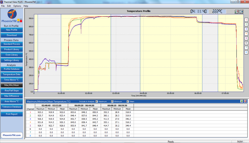
Figure 3: Thermal view SW displaying the temperature profile from a carburizing with gas quench process
In thru-process temperature monitoring, the data logger collects raw process data directly from the product or furnace as it follows the standard production flow. To understand the data to allow process control and optimization, a Thermal View software analysis is used.
Using a range of analysis tools, the engineer can interpret the raw data. Key analysis calculations can be performed such as:
Max / Min — Check maximum and minimum product temperature over whole product or product basket through phases of process carburizing, diffusion and quench.
Time @Temp — Confirm that the soak time above required carburizing temperature is sufficient for correct carbon diffusion and surface properties.
Temperature Slopes —Measure the quench rate of the product to ensure that the hardening process is performed correctly.
Next up in the series: Designing an Innovative Thermal Barrier — The carburizing process by its nature is very demanding when considering protection of the datalogger from high temperatures and rapid temperature and pressure changes experienced in either the gas or oil quench.
The demand in aerospace manufacturing for brazing technology is likely to increase as the alloys developed and manufactured through the process are used for more applications — from turbine blades to rocket nozzles to hydraulic assemblies.
“Brazing is used just about everywhere—it’s difficult to classify.” ~ Ed Arata, brazing engineer, Morgan Advanced Materials
Brazing may be difficult to classify, but the process can be explained, and its subsequent value to aerospace design and manufacturing groups is explored in this Best of the Web article from MRO-Network.com
David B. Burritt, President and Chief Executive Officer
A leading integrated steel producer headquartered in Pittsburgh, Pennsylvania, recently announced it will restart its pipe ill based in Lone Star, Texas.
U.S. Steel Corporation’s No. 1 Electric-Weld Pipe Mill at Lone Star Tubular Operations was permanently idled in 2016 due to challenging market conditions for tubular products created by fluctuating oil prices, reduced rig counts, and high levels of unfairly traded imports. With this restart, the Lone Star No. 1 Mill will provide full-body normalized electric-welded pipe in size ranges 7 inches to 16 inches outside diameter for customers across the U. S., including the very active Permian Basin.
“We are encouraged by an improvement in market conditions and an increased customer demand for tubular products that are mined, melted and made in America,” said President and Chief Executive Officer David B. Burritt.
Douglas R. Matthews, Senior Vice President – Industrial, Service Center and Mining Solutions and Interim Head – Tubular
“We continue to evaluate all options to align our manufacturing capacity with the growing energy market. Restarting the Lone Star No. 1 Mill will give our customers access to the high-quality electric-welded pipe they expect from U. S. Steel,” said Douglas R. Matthews, Senior Vice President – Industrial, Service Center and Mining Solutions and Interim Head – Tubular.
The Lone Star No. 1 Mill has an annual capacity of approximately 400,000 tons. The restart process will begin immediately and will be completed in early third quarter 2019.
When the U.S. Air Force flies its new advanced pilot trainer from Boeing and Saab, it will be equipped with an ACES 5® ejection seat along with a fully integrated landing gear system.
John “Barney” Fyfe, Air Force programs director for Collins Aerospace
Both will be supplied by Collins Aerospace, the entity that resulted from the recent merging of UTC Aerospace Systems and Rockwell Collins. Collins is a unit of United Technologies Corp, headquartered in Farmington, Connecticut, and provides heat treating capabilities among its high-technology systems and services to the building and aerospace industries.
ACES 5 offers passive head and neck protection, arm and leg flail prevention, and a load-compensating catapult rocket that varies its thrust based on the occupant’s weight. In addition to ACES 5, Collins will supply the aircraft’s fully integrated landing gear system, including structure, actuation, dressings, hydraulics, and wheels and brakes. The system boasts several technological innovations designed to help reduce maintenance costs while improving operational performance.
“Collins Aerospace is honored to be a supplier for Boeing in support of the U.S. Air Force’s next-generation trainer program and proud to provide a host of integral content, including our ACES 5 ejection seat and fully integrated landing gear system,” said John “Barney” Fyfe, Air Force programs director for Collins Aerospace. “Our innovative technologies will play a critical role in helping to keep aircrews safe, reducing maintenance costs, and improving operational performance. Our support for Boeing military aircraft dates back to 1932 with the P-26, and we look forward to continuing to work with the Boeing and Saab team on the T-X program in the years to come.”
The study was led by James Pikul, Assistant Professor in the Department of Mechanical Engineering and Applied Mechanics at Penn Engineering.
We’ve come a long way in the search for and application of lightweight metals, which are being used now in everything from high-performance golf clubs to airplane wings, but random defects that arise in the manufacturing process mean that these materials are only a fraction as strong as they could theoretically be.
In a new study published in Nature Scientific Reports, researchers at the University of Pennsylvania’s School of Engineering and Applied Science, the University of Illinois at Urbana–Champaign, and the University of Cambridge have designed and built materials that are stronger than anything heretofore developed, using a sheet of nickel with nanoscale pores that make it as strong as titanium but four to five times lighter.
“The empty space of the pores and the self-assembly process in which they’re made make the porous metal akin to a natural material, such as wood.
And just as the porosity of wood grain serves the biological function of transporting energy, the empty space in the researchers’ “metallic wood” could be infused with other materials. Infusing the scaffolding with anode and cathode materials would enable this metallic wood to serve double duty: a plane wing or prosthetic leg that’s also a battery.”
Photo credit/caption: Penn Engineering/A microscopic sample of the researchers’ “metallic wood.” Its porous structure is responsible for its high strength-to-weight ratio, and makes it more akin to natural materials, like wood.
This is the seventh in a series of articles by AMS2750 expert, Jason Schulze (Conrad Kacsik). Click here to see a listing of all of Jason’s articles on Heat TreatToday. In this article, Jason advances the discussion of initial and periodic TUS requirements. Please submit your AMS2750 questions for Jason to editor@heattreattoday.com.
Introduction
Any technician who has performed a Temperature Uniformity Survey (TUS) understands that the assembly, use, and placement of thermocouples is imperative to the success of the TUS.
As we move through the requirements of Temperature Uniformity Surveys, we will examine the requirements that apply to TUS thermocouples.
Initial Temperature Uniformity Surveys
Before we get started, let’s take a look at how AMS2750E describes :
An initial TUS shall be performed to measure the temperature uniformity and establish the acceptable work zone and qualified operating temperature range(s). Periodic TUS shall be performed thereafter in accordance with the interval shown in Table 8 or 9. ~ AMS2750E page 23, paragraph 3.5.1
Most companies, whether purchasing a new furnace or used one, know what they would like the acceptable work zone size and qualified operating range to be. I emphasize “would like” because what we would like our furnaces to be capable of is not always what they are able to do. We would like to use every square meter of our furnace control zone in an effort to maximize capacity and, of course, maximize profit on each cycle we process. We would like our furnaces to operate at the very limits of what the furnace manufacturer states it can do. Unfortunately, these items don’t always exist once the furnace is subjected to an initial Temperature Uniformity Survey per AMS270E.
An initial TUS is used to tell us what our furnaces can do based on pre-determined parameters. Normally, these parameters should be flowed down to our furnace manufacturers, and prior to shipping, these parameters are compared to what the furnace can actually attain making the furnace conformative and ready for shipment. I strongly recommend this whenever purchasing a new or used furnace.
Initial temperature uniformity testing requirements are as follows;
Initial survey temperatures shall be the minimum and maximum temperatures of the qualified operating temperature range(s).
Additional temperatures shall be added as required to ensure that no two adjacent survey temperatures are greater than 600 °F (335 °C) apart.
These requirements are simple and straight forward. One could argue that I may be oversimplifying the requirements of an initial TUS, but let’s not forget, these are merely the requirements, not the conditions, under which an initial TUS must be performed. Let’s look at an example that would conform to the stated requirements.
Example
A furnace (in this case, it is irrelevant what type of furnace or what it is used for) processes production hardware from 900°F to 2200°F. Based on the requirements of AMS2750E, the initial TUS would start by testing at 900°F and the last temperature tested would be 2200°F. The supplier would need to select temperatures between 900°F and 2200°F to ensure that there is no more than a 600°F gap between each adjacent temperature. Figure 1 is an example of temperatures that could be selected.
Figure 1
We’ve covered the requirements of an initial TUS; we will now address the conditions when an initial TUS is required. Initial TUSs are required when a) the furnace is installed (new or used) and b) when any modifications are made that can alter the temperature uniformity characteristics. You could dispute this by stating if a TUS fails (and the furnace is then repaired to be put back in service), if the qualified work zone is expanded, if a thicker control thermocouple is installed, etc. a new initial TUS is required. I would agree, but these would all fall under “B”.
Periodic Temperature Uniformity Surveys
Periodic TUSs are performed for single operating ranges greater than 600°F. In this case, the temperatures are selected must be 300°F from the minimum- and 300°F from the maximum-qualified operating range. If there is a gap of greater than 600°F, additional temperatures must be selected so there is no gap greater than 600°F. Using the example above, we could select temperatures as stated in Figure 2 below.
Figure 2
It is required that at least once each calendar year the minimum and maximum temperatures of the qualified operating range (in our example, it would be 900°F and 2200°F) are tested. Some suppliers may choose to perform an initial TUS once per year to ensure they capture the minimum and maximum.
Initial and Periodic Test Frequency
Tables 8 and 9 within AMS2750E describe the TUS frequency which is based both on furnace Class and Instrumentation Type. As an example, if our furnace referenced previously was identified as a Class 3 (±15°F), Type A instrumentation, the initial survey frequency would be quarterly. After two successful consecutive surveys, the frequency of testing could then be extended to being done annually.
It is important to recognize the difference between initial and periodic TUS temperatures and initial and periodic TUS frequency. Let’s use our example to expand on this. The supplier would perform a TUS using initial temperatures shown in Figure 1. If the TUS passes, the supplier would then, three months later, perform a TUS using the temperatures shown in Figure 2. This would then count as two successful consecutive TUSs. The next TUS could then be performed annually using the temperatures stated in Figure 2.
Conclusion
Understanding initial and periodic TUS requirements is imperative to ensure conformance to AMS2750E and Nadcap. In the next installment, we will discuss TUS data collection, relocation of hot and cold thermocouples, as well as quality requirements.
Submit Your Questions
Please feel free to submit your questions, and I will answer appropriately in future articles. Send your questions to editor@heattreattoday.com.
An international technology enterprise recently broke ground on the company’s new facility for its Industrial Quality and Research division.
Dr. Jochen Peter, Member of the Executive Board of the ZEISS Group and Head of the Industrial Quality and Research segment
ZEISS has begun construction on the new modern site near Detroit, Michigan, which will provide a broad portfolio of dimensional metrology and inspection equipment and services to a wide variety of industries including automotive, medical, aerospace, defense, machine tools, and general manufacturing job shops. ZEISS Industrial Quality Solutions will offer system demonstrations for customers as well as metrology services.
“We are investing over 45 million dollars in the Detroit metro region to strengthen and increase our engagement in this global automotive and smart factory hot spot,” said Dr. Jochen Peter, Member of the Executive Board of the ZEISS Group and Head of the Industrial Quality and Research segment. “This will not only have a strong, positive impact for our customers and partners in North America but will also generate new momentum for the whole Industrial Quality and Research segment of ZEISS worldwide.”
Michael Kirchner, member of the leadership team for the ZEISS Industrial Quality Solutions strategic business unit and Head of its business in North America
“With the new ZEISS Center in Michigan, we aim to assure a higher level of satisfaction with our solutions for our customers and provide a more attractive working environment for our team,” said Michael Kirchner, member of the leadership team for the ZEISS Industrial Quality Solutions strategic business unit and Head of its business in North America.
ZEISS measuring specialists will be able to perform proof-of-capability demonstrations for multidimensional measurement equipment, surface form and geometry equipment, and non-destructive testing and surface defect detection equipment. The need to show how digital platforms and solutions that connect ZEISS equipment to the new infrastructure within modern smart factory environments is becoming increasingly important.
It will also be a center for aftermarket sales support. Here customers will receive training on how to use the software and systems. Additionally, software help desk services will operate out of the facility.
Photo caption: ZEISS groundbreaking event for new state-of-the-art facility in Detroit metro area