AUTOMOTIVE HEAT TREAT

Dig into the Archives: 5 Technical Articles for Fresh Heat Treaters in Auto

OCAre you a relatively new reader in automotive heat treat? Welcome. Enjoy this archive of articles from the automotive industry, which provides years of technical knowledge to fill any information gaps. Even the "OG" readers with Heat Treat Today will want to investigate this Technical Tuesday original content compilation that plumbs the depths of the archives.


1. What Heat Treatment To Use for Truck Gear Boxes?

Fig. 2. Schematic depiction of pusher furnace (l.) and 3D batch of helical gears (r.)
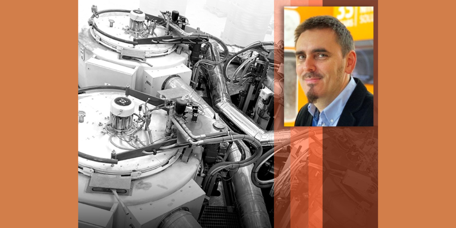
This paper reveals the investigation and conclusions of distortion potentials for case hardening processes. Mainly, the focus was on how the SyncroTherm® concept method compared to conventional case-hardening processes for gears and sliding sleeves.

Contact us with your Reader Feedback!

Read about how the results effected the bottom line: reduced costs, quicker processes, and less distortion. Also, be sure to examine each of the charts and figures for further understanding of each test.

This article entered the Automotive Heat Treat archive in 2016, and was written by Andreas Schüler, Dr.-Ing. Jörg Kleff, Dr. Volker Heuer, Gunther Schmitt, and Dr. Thorsten Leist.

Read about here: "Distortion of Gears and Sliding Sleeves for Truck Gear Boxes – a Systematical Analysis of Different Heat Treatment Concepts"


2. Cracking the Case

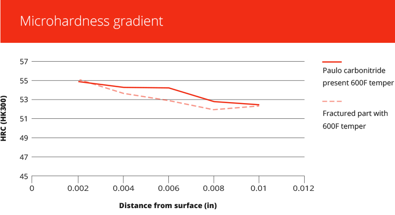
Problems in heat treating result in the loss of valuable time and money. Getting to the bottom of those problems also usually takes time and money to investigate what's happening and how to fix it. What is a heat treater to do?

In this article, we follow a case study from the automotive industry to understand how to pinpoint a heat treating problem. This article specifically looks at what was causing cracking in variable valve timing (VVT) plates.

Read the 2018 article, "Part Failure Investigation & Resolution — A Case Study," by Rob Simons.


3. Carburizing: The Importance of Temperature Monitoring and Surveying

Temperature Monitoring and Surveying Solutions for Carburizing Auto Components: Introduction
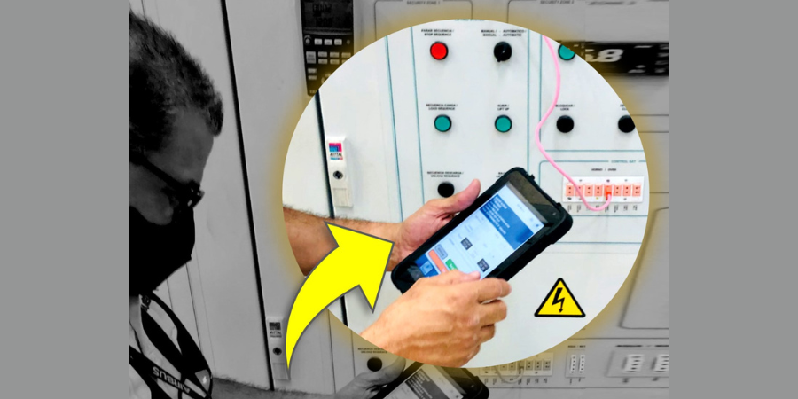
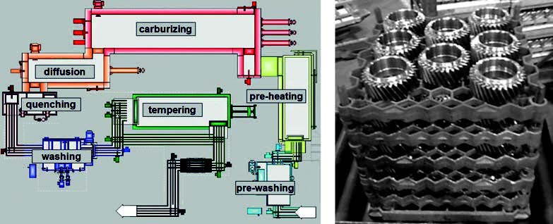
Low pressure carburizing (LPC) furnaces play an important role in the automotive heat treating industry. During LPC, it is essential that processing temperature stays consistent and critical that the processing time frame is monitored.

This article discusses the importance of collecting temperature data and what to do with the data when it's been collected.

Throughout 2019, Dr. Steve Offley wrote for this series, beginning with this part 1, "Temperature Monitoring and Surveying Solutions for Carburizing Auto Components: Introduction." When you're through, enjoy part 2, part 3, and part 4.


4. Vacuum Brazing --- Back to the (Automotive) Basics

Vacuum Brazing for Automotive Applications
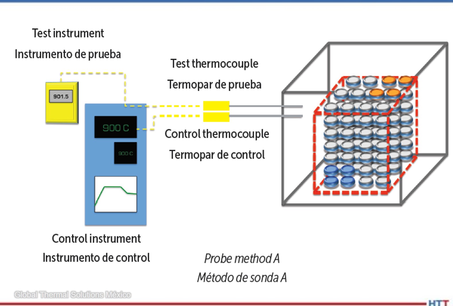
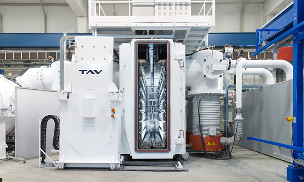
Time to brush up on a vacuum brazing furnace, but automotive industry style. Review the terms, parts, function, and more that are involved in a successful vacuum braze for automotive parts.

This study covers a semi-automatic TAV vacuum brazing furnaces, details the makeup of the furnace, and gives an idea of what happens with a load from start to finish.

Read this 2019 article by Alessandro Fiorese here: "Vacuum Brazing for Automotive Applications."


5. Saving Time --- Automation Versus Manual Hardness Tests

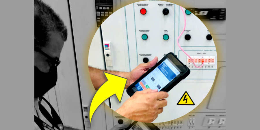
If you've ever heat treated automotive crank pins, you're probably familiar with at least one type of hardness test that case hardened crank pins are tested against. The big question is, which hardness testing method is better: automated or manual? This article compares these two methods to make and measure Vickers indentations.

Evaluate for yourself the comparisons between an experienced operator manually entering data to Wilson VH3100 series Vickers Microhardness Tester and a DiaMet software entry. Some additional findings show that the crank pins could be examined by the Wilson tester with far less manipulation in the vice as well as reduction in data recording mistakes.

When you read this 2020 article by Buehler, "Manual Versus Automated Hardness Testing", learn exactly how much time, exactly, is saved with automation.


Find heat treating products and services when you search on Heat Treat Buyers Guide.com


Dig into the Archives: 5 Technical Articles for Fresh Heat Treaters in Auto Read More »

Factorial Energy Announces Plans for EV Cell Pilot Production Facility

HTD Size-PR Logo

Factorial Energy (Factorial), a developer of solid-state battery technology for electric vehicle applications, announced it will establish a new advanced manufacturing facility in the Boston suburb of Methuen, MA. The new facility will produce Factorial’s new solid-state battery cell technology for EVs.

Siyu Huang
Founder and CEO
Factorial Energy

The new production site at 501 Griffin Brook Drive in Methuen has an existing 67,000 square-foot building on the site that will undergo extensive buildout to house Factorial’s pilot production facility. The facility expects to begin operations in early 2023 and will bring 166 new jobs to the Methuen community.

Based in Woburn, MA, the company is currently working with automakers Hyundai Motor Company, Mercedes-Benz, and Stellantis to develop safer and higher performance solid-state EV battery cells for future passenger and commercial vehicles.

"We plan to continue building solid-state EV battery research and development facilities in New England and establish the region as a hub for electric mobility technology," commented said Siyu Huang, CEO of Factorial.


Find heat treating products and services when you search on Heat Treat Buyers Guide.com


Factorial Energy Announces Plans for EV Cell Pilot Production Facility Read More »

Heat Treat Furnaces To Improve Hardening Capabilities for Aalberts

Alberto Martin
Sales Director -- Spain
Aalberts surface technologies TEY

HTD Size-PR LogoInternational manufacturer Aalberts surface technologies Group will receive two vacuum furnaces to the group’s Spanish branch in País Vasco. The system on order solves the manufacturer's problem with hardening large dimension elements.

The manufacturer mainly operates in the automotive industry, as well as the machine industry and, with this order, has signed its tenth contract with international furnace supplier, SECO/WARWICK. Aalberts is ordering the heat treat furnace provider's horizontal retort furnace for high-efficiency tempering with vacuum purging and the Vector® vacuum furnace. The Vector, with a useful working space of 600mm x 600mm x 900mm will increase the efficiency of the current hardening plant, improving the economics of hardening processes. The retort furnace will significantly increase the processing capacity of the current hardening plant for tempering processes.

Once again, SECO/WARWICK equipment will contribute to increasing the efficiency of our entire Group," said Alberto Martin, director of Sales --- Spain at Aalberts surface technologies TEY. Aalberts surface technologies is a global company with over 80 years of experience, operating in over 70 countries.


Find heat treating products and services when you search on Heat Treat Buyers Guide.com


Heat Treat Furnaces To Improve Hardening Capabilities for Aalberts Read More »

Top 3 Heat Treat Grab and Go Visuals

OCWe get it. You read all day: emails, memos, furnace monitoring screens. To give your eyes a break, Heat Treat Today wanted to provide some grab and go visual resources. In this original content piece, check out some visuals to help you learn about the difference between Nitriding and FNC; discover how the U.S. is doing in the race to green steel production; and get an example of the type of numbers that are normal for a CQI-9 probe method A test.


The Numbers Don't Lie: Green American Steel Is Better than You Think

Contact us with your Reader Feedback!

In Heat Treat Today's August 2021 Automotive print edition, Lourenco Goncalves, chairman, president, and CEO of Cleveland-Cliffs, Inc. made a big statement: "The United States is the benchmark of the world in all things steel. Amongst all major steelmaking nations, we have by far the greenest emissions profile."

In a climate where the United States often gets a bad rap when it comes to environmental concerns, Lourenco's statement is hard to believe. But, the data below contradicts this bad reputation. Check out the graphic below to learn how the United States stacks up to other countries in steel production.

CQI-9: Understanding Probe Method A

Ensuring heat treating equipment falls within CQI-9 standards can be tricky. According to Erika Zarazúa, regional purchasing manager at Global Thermal Solutions, probe method A may be the best way to identify variations in control systems.


If you're curious about how probe method A works, view the chart below (in both English and Spanish) for an example of the kind of numbers that are typical for this test method.

Table 1. Probe method A
Tabla 1. Método de sonda A


Nitriding vs. FNC . . . What's the Difference?

These days, it seems like most heat treat shops are updating equipment or changing procedures to accommodate demands for ferritic nitrocarburizing. But how different are the two processes, really? When it comes to materials commonly processed, time cycles involved, and atmospheres required, where does the difference between nitriding and FNC begin? The chart below is a quick and easy guide to distinguishing the difference between these two hardening processes. Skim away or take a deep dive into the technicalities!

About the Authors:

Lourenco Goncalves is chairman, president, and CEO of Cleveland-Cliffs, Inc

Erika Zarazúa, a 40 Under 40 Class of 2021 member, is a metallurgical engineer with over 18 years of experience in heat treatment operations and temperature measurement and has worked in multiple engineering, quality, and project roles in the automotive and aerospace industries. Erika currently holds the position of regional purchasing manager at Global Thermal Solutions.

 Jason Orosz and Mark Hemsath at Nitrex, Thomas Wingens at WINGENS LLC – International Industry Consultancy, and Dan Herring, The Heat Treat Doctor at The HERRING GROUP, Inc., provided expert input for the Nitriding vs. FNC table.


Find heat treating products and services when you search on Heat Treat Buyers Guide.com


Top 3 Heat Treat Grab and Go Visuals Read More »

Gear Manufacturer Gains Nitriding Capacity with 2 Heat Treat Furnaces

HTD Size-PR Logo

The Capi Group has boosted its nitriding/nitrocarburizing capacity with two heat treat furnaces to keep up with the rise in production and new orders from the industrial and automotive sectors.

Marcin Stokłosa
Project Manager
Nitrex Poland
LinkedIn.com

The Italian gear manufacturer's order of Nitrex's large-capacity nitriding systems "is a continuation of our collaboration, and we look forward to strengthening this partnership further,” says Marcin Stokłosa, project manager at Nitrex.

The Capi Group owns four pit-type nitriding/nitrocarburizing furnaces of the same model type and larger size, which consist of  Nitreg® and Nitreg®-C technologies, +/-3°C temperature homogeneity in the retort, and eco-friendly IN-500 exhaust neutralizer to support a clean and green operation.

The new Nitrex furnaces, which comply with the Aerospace Material Specifications (AMS) 2750 for pyrometry and 2759/10 for controlled nitriding, are integrated into the existing production line and connected to a closed-loop water cooling system. The latter is an environmentally friendly feature that recirculates a steady supply of cooling water to cool furnace elements.

The new systems have been operational for a few months.


Find heat treating products and services when you search on Heat Treat Buyers Guide.com


Gear Manufacturer Gains Nitriding Capacity with 2 Heat Treat Furnaces Read More »

CAB Line Selected for EV In-House Heat Treating

HTD Size-PR Logo

An international automotive conglomerate has selected a controlled atmosphere brazing line for their newly established factory in Mexico. The heat treat system will be used to process EV batteries.

5th CAB line for global automotive manufacturer

Piotr Skarbiński
Vice President of Aluminum and CAB Products Segment
SECO/WARWICK
Source: LinkedIn

While this is the 5th CAB line that SECO/WARWICK has provided to the manufacturer, this specific heat treat system --- the EV/CAB line --- is designed with the electric vehicle (EV) sector in mind to braze large-size car battery coolers for the EV industry. The system includes a brazing furnace, convection preheating chamber, cooling chamber with air jacket, final cooling chamber, and control system.

"This is the customer’s first order outside the Asian market," commented Piotr Skarbiński, vice president of Aluminum and CAB Products Segment at SECO/WARWICK. He continued, saying, "We are glad [to] be involved in this project." SECO/WARWICK will commission this solution and execute the start-up on-site.

This solution is provided within the global context of increased demand for battery coolers due to the growing production of electric vehicles.


Find heat treating products and services when you search on Heat Treat Buyers Guide.com


CAB Line Selected for EV In-House Heat Treating Read More »

Guide To Conducting SATs According to CQI-9 4th Edition

OCThe AIAG CQI-9 (Heat Treat System Assessment) is the most accepted standard in the automotive industry for the validation of heat treatment operations. This article summarizes the evaluation requirements and illustrates the benefits of conducting this test to identify variations in control systems using the probe method A.

Read the English translation of this Technical Tuesday article by Erika Zarazúa, regional purchasing manager at Global Thermal Solutions, in the version below, or read both the Spanish and the English translation of the article where it was originally published: Heat Treat Today's August 2022 Automotive print edition.

"La evaluación CQI-9 (Heat Treat System Assessment) de AIAG es el estándar mas aceptado en la industria automotriz. . . ."


Erika Zarazúa
Regional Purchasing Manager 
Global Thermal Solutions México
Source: Global Thermal Solutions México

1. Application

System Accuracy Tests (SATs) must be performed on all control, monitoring, and recording systems of thermal processing equipment. This does not apply to “high limit” systems, whose sole function is to protect the furnace from overheating.

Contact us with your Reader Feedback!

The test thermocouple used for the SAT must meet the accuracy requirements defined by CQI-9 in table P3.1.3 (±1.1°C or ±2°F maximum error). Similarly, table P3.2.1 of the same section defines the requirements for the field test instrument (±0.6°C or ±1°F maximum error).

SATs conducted by “probe method” should be performed quarterly or after any maintenance that could affect the accuracy of the measurement system such as:

  • Replacement of lead wire
  • Replacement of the control thermocouple
  • Replacement of the control/recording instrument

2. Procedure (Probe Method A)

Probe method A is a comparison between the furnace temperature reading and a corrected test temperature reading.

Table 1. Probe method A
Tabla 1. Método de sonda A

When inserting the test thermocouple, ensure that the tip of the probe is placed as close as possible to the tip of the thermocouple to be tested, and no further than 50mm. Once placed in the test position, it is recommended to allow some time for both systems to reach equilibrium before conducting the test.

If the difference between the furnace temperature reading and corrected reading of the test system exceeds ±10°F (±5°C), then corrective actions must be conducted before processing a product. The most common corrective actions are to replace the control thermocouple, calibrate and adjust the control/recording instrument, or to combine both methods. According to CQI-9, these actions must be documented.

3. Records

CQI-9 revision 4 specifies that the SAT must be documented, and the records must include, at a minimum, the following information:

a. Furnace thermocouple identification
b. Test thermocouple identification
c. Identification of the test instrument
d. Date and time of the test
e. Setpoint value
f. Reading observed in the control system
g. Observed reading on test system
h. Thermocouple and test instrument correction factors
i. Test system corrected reading
j. Difference calculated from the SAT
k. Name and signature of the technician performing the test
l. Company performing the test (if external)
m. ISO/IEC 17025 accreditation of the company (if external)
n. Approval of the person responsible for heat treatment

4. Conclusion

The pyrometry section of CQI-9 lists the requirements and procedures for conducting system accuracy tests (Section P3.3). Within CQI-9, there are two important requirements heat treaters must be aware of. First, the furnace temperature measurement system must not deviate more than ±10°F (±5°C) from the test system. If this is the case, the equipment must not be used for thermal processing and corrective actions must be taken. Second, the SAT report must contain each time this test is conducted. With probe method A, variations in controls systems are easily identifiable.


References

[1] CQI-9 Special Process: Heat Treat System Assessment, 4th Edition. Automotive Industry Action Group, 2020.

[2] International Organization for Standardization; ISO/IEC 17025, General requirements for the competence of testing and calibration laboratories, 3rd Edition. International Organization for Standardization, 2017.

(Photo source: Global Thermal Solutions)


About the Author: Erika Zarazúa, a 40 Under 40 Class of 2021 member, is a metallurgical engineer with over 18 years of experience in heat treatment operations and temperature measurement and has worked in multiple engineering, quality, and project roles in the automotive and aerospace industries. Erika currently holds the position of regional purchasing manager at Global Thermal Solutions.

Contact Erika: erika@globalthermalsolutions.com


Find heat treating products and services when you search on Heat Treat Buyers Guide.com


Guide To Conducting SATs According to CQI-9 4th Edition Read More »

Guía para conducir pruebas System Accuracy Tests conforme a CQI-9 4ta. Edición

OCThe AIAG CQI-9 (Heat Treat System Assessment) is the most accepted standard in the automotive industry for the validation of heat treatment operations. This article summarizes the evaluation requirements and illustrates the benefits of conducting this test to identify variations in control systems using the probe method A.

Read the Spanish translation of this article by Erika Zarazúa, gerente regional de compras de Global Thermal Solutions México, in the version below, or read both the Spanish and the English translation of the article where it was originally published: Heat Treat Today's August 2022 Automotive print edition.

La evaluación CQI-9 (Heat Treat System Assessment) de AIAG es el estándar mas aceptado en la industria automotriz para la validación de operaciones de tratamiento térmico y, entre muchas cosas, describe los requisitos generales y el procedimiento para conducir las pruebas SAT (System Accuracy Test) a los sistemas medición de temperatura de los equipos de procesamiento térmico. Este artículo sintetiza los requerimientos de la evaluación e ilustra los beneficios de conducir esta prueba para identificar variaciones en los sistemas de control mediante el método de sonda “A”.


Erika Zarazúa
Gerente Regional de Compras 
Global Thermal Solutions México
Source: Global Thermal Solutions México

1. Aplicación

Las pruebas SAT deben realizarse a todos los sistemas de control, monitoreo y registro de los equipos de procesamiento térmico. Esto no aplica para los sistemas de ‘alto-límite” cuya única función es la de proteger al horno de un sobre calentamiento.

Contact us with your Reader Feedback!

El termopar de prueba empleado para la prueba SAT debe cumplir con los requisitos de precisión que define CQI-9 en la tabla P3.1.3 de la sección de Pirometría (±1.1°C o ±2°F máximo de error). De igual manera, la tabla P3.2.1 de la misma sección define los requisitos para el instrumento de prueba - field test instrument (±0.6°C o ±1°F máximo de error).

Las pruebas SAT por el método de sonda deben realizarse trimestralmente o después de algún mantenimiento que pudiera afectar la precisión del sistema de medición como:

  • Reemplazo del cable de extensión
  • Reemplazo del termopar de control
  • Reemplazo del instrumento de control/registro

2. Procedimiento (Método de sonda A)

El método de sonda A es una comparación entre la lectura del sistema de medición del horno y un sistema de medición de prueba corregido:

Table 1. Probe method A
Tabla 1. Método de sonda A

Al insertar el termopar de prueba, se debe asegurar que la punta se coloque lo mas cerca de la punta del termopar a ser probado, y no mas lejos de 50mm. Una vez colocado en la posición de prueba, se recomienda permitir cierto tiempo para que ambos sistemas alcancen un equilibrio antes de conducir la prueba.

Si la diferencia entre el sistema de medición del horno y sistema de prueba corregido excede de ±5°C (±10°F) entonces se deben conducir acciones correctivas antes de procesar producto. Las acciones correctivas mas comunes consisten en reemplazar el termopar de control, calibrar y ajustar el instrumento de control/registro o una combinación de ambas. De acuerdo a CQI-9, estas acciones deben ser documentadas.

3. Registros

CQI-9 revisión 4 especifica que la prueba SAT debe documentarse y los registros deben incluir como mínimo la siguiente información

a. Identificación del termopar del horno
b. Identificación del termopar de prueba
c. Identificación del instrumento de prueba
d. Fecha y hora de la prueba
e. Valor del setpoint
f. Lectura observada en el sistema de control
g. Lectura observada en el sistema de prueba
h. Factores de corrección del termopar e instrumento de prueba
i. Lectura corregida del sistema de prueba
j. Diferencia calculada del SAT
k. Nombre y firma del técnico que realiza la prueba
l. Compañía que realiza la prueba (si es externa)
m. Acreditación en ISO/IEC 17025 de la compañía (si es externa)
n. Aprobación del responsable de tratamiento térmico

4. En resumen

La sección de Pirometría de CQI-9 revisión 4 indica los requerimientos y el procedimiento para la realización de la prueba SAT (Sección P3.3).

El sistema de medición de temperatura del horno no debe presentar una desviación mayor a los ±5°C (±10°F) respecto al sistema de prueba. Si este fuera el caso, el equipo no debe usarse para procesamiento térmico y deben aplicarse acciones correctivas.

CQI-9 especifi ca la información que debe contener el informe de SAT cada vez que se conduce esta prueba.


Referencias

[1] Automotive Industry Action Group; CQI-9 Special Process: Heat Treat System Assessment, 4rd Edition, June 2020.

[2] International Organization for Standardization; ISO/IEC 17025, General requirements for the competence of testing and calibration laboratories. 3rd Edition, 2017.

(Fuente de la foto: Global Thermal Solutions)

Sobre el autor: Erika Zarazúa es Ingeniera Química Metalúrgica por parte de la Universidad Autónoma de Querétaro. Con más de 18 años de experiencia en operaciones de tratamiento térmico y medición de temperatura, ha trabajado en múltiples roles de ingeniería, calidad y proyectos en las industrias automotriz y aeroespacial. Actualmente ocupa el cargo de Gerente Regional de Compras de Global Thermal Solutions.

Contacto Erika: erika@globalthermalsolutions.com


Find heat treating products and services when you search on Heat Treat Buyers Guide.com


Guía para conducir pruebas System Accuracy Tests conforme a CQI-9 4ta. Edición Read More »

Heat Treat IQ System for Härtewerk Chemnitz Hardening Plant

HTD Size-PR Logo

Kai Werlitz
Technical Operations Manager
Härtewerk Chemnitz GmbH
Source: Härtewerk Chemnitz

Härtewerk Chemnitz GmbH, a large German commercial hardening plant (Lohnhärterei), has purchased a horizontal, two-chamber furnace low-pressure carburizing and oil quenching system from an international heat treat solutions provider. In the German plant, the integral quench system will replace legacy atmosphere technology and expand their capabilities for mass-producing parts.

This is the first SECO/WARWICK furnace equipped with vacuum heating at the heat treater's German plant and the first Super IQ solution in Germany. The system has a heating chamber, loading and unloading vestibule, and a quenching bath. The equipment in the system enables users to perform a variety of heat treatment processes, heat, and chemical treatment, as well as low-pressure carburizing and quenching.

"The machines we have worked with so far had required time-consuming and expensive preparation, especially when the equipment was not at the right temperature," commented Kai Werlitz, technical operations manager at Härtewerk Chemnitz GmbH. "The Super IQ furnace that we have ordered eliminates not only these difficulties but also enables efficient heat treatment with very high repeatability and uniformity of the carburized layer, which with atmospheric furnaces was only possible to a limited extent."

The heat treater's Chemnitz and Chomutov plants provide a wide range of services related to metal heat treatment and focus on Germany and Europe's mechanical engineering, automotive, and metalworking industries.


Find heat treating products and services when you search on Heat Treat Buyers Guide.com


Heat Treat IQ System for Härtewerk Chemnitz Hardening Plant Read More »

Parallel Positioning Burner Controls for Uniform Temperature

OCIs there a way to combine pulse firing and fuel-only modulation without retaining the downsides of either method? Parallel positioning of burner controls may just be the win-win solution heat treaters are looking for.

This Technical Tuesday, written by Scott Fogle, national account executive at Siemens Combustion Controls, first appeared in Heat Treat Today's August 2022 Automotive print edition.


Scott Fogle
National Account Executive
Siemens Combustion Controls

Two common burner control methods for uniform furnace temperature needing Nadcap and AMS2750F requirements are pulse firing and fuel-only modulation. High convective heat transfer of the gases in the furnace results in good uniformity. Pulse firing keeps burners at high fire using on/off cycle times, and fuel-only modulation uses a constant high velocity of the combustion air. Both methods have a downside. When the cycle times of pulse firing are short for low temperature setpoints, the stirring effect is reduced, resulting in temperature uniformity challenges. Fuel-only modulation uses large amounts of excess air which is inefficient especially at high furnace temperatures.

Contact us with your Reader Feedback!

Parallel positioning offers a hybrid solution between pulse firing and fuel-only modulation. Parallel positioning independently controls the air and fuel on each burner. This control modifies the air-to-fuel ratio based on firing rate. At high firing rates of approximately 50% and above, the burner can be set to a stoichiometric ratio for the highest efficiency. When the firing rate falls below 50%, stoichiometric operation loses the high velocity stirring effect needed to obtain good uniformity. To maintain the stirring effect, excess air is added as the firing rate decreases. The air curve on a firing rate verses valve position chart looks like the letter “V.” Firing efficiently at high firing rates and adding excess air at low firing rates combines the best of pulse firing and fuel-only modulation in one solution.

Combustion curve

When conducting a temperature uniformity survey, parallel positioning offers flexibility to make minor adjustments to both the air and fuel of a burner. To correct cold spots and hot spots during a survey, there are four options available to tune the burner closest to the cold/hot spot at a particular firing rate: 1) increase air 2) decrease air 3) increase fuel and 4) decrease fuel. These adjustments of air and gas flow converge the temperature readings together for uniformity at multiple temperature setpoints.

Parallel positioning offers a couple other advantages as well. Many of these systems allow for an independent ignition position for each actuator: air and gas. A burner technician can set ignition for each burner at an elevated level and perhaps a rich mixture to increase the likelihood of reliable ignition in all cases, without compromising on turndown. If a specific firing rate and/or ratio does not suit a burner well, maybe the burner resonates or the flame signal weakens, the air fuel mixture can be adjusted independently at that point to minimize the undesirable characteristic.

Parallel positioning air fuel ratio control has been around for decades under the hoods of our cars, and for nearly that long in several large burner applications too. As these systems have become more reliable and less expensive, the benefits can be enjoyed by many other combustion applications. We’ve seen several furnaces take advantage of these benefits for improved operation in recent years.


About the Author: Scott Fogle is a national account executive with Siemens Combustion Controls based out of the Chicagoland area. He previously served as a combustion engineer for a globally recognized burner manufacturer. Scott holds 10 years of experience in the field of combustion and serves as an alternate on the NFPA 86 committee. Contact Scott at sfogle@scccombustion.com.


Find heat treating products and services when you search on Heat Treat Buyers Guide.com


Parallel Positioning Burner Controls for Uniform Temperature Read More »