Heat TreatToday publishes twelve print magazines a year and included in each is a letter from the publisher, Doug Glenn. This letter first appeared in March 2025 Aerospace Heat Treatingprint edition.
The world is a better place when people know what their job is and then stick to that job. When the carpenter knows that their job is working with wood and then works with wood, things go well. When the pipefitter doesn’t try to be an electrician but sticks to pipefitting, things go well. It’s only when we forget (or never knew) who we are or why we’re here that things begin to go terribly wrong.
This is just as true in the C-suite as it is on the shop floor when it comes to running a business. CEO, CFO, COO, presidents, and VPs all benefit the business by sticking to their huckleberry bush just as the welder, the electrician, and the plant operations guys prosper the business when they do what they’re called to do.
In the C-suites, however, there seems to be more confusion about what it is they are there to do and company leaders more frequently get distracted from their huckleberry bush than do the guys in the shop. Here are some good, yet ultimately unhelpful things that have kept company leadership from focusing on profits — which ought to be their huckleberry bush.
Environmental Concerns
If ever there was a worthy cause, caring for the planet should be toward the top of the list, coming in second only behind caring for people. Business leaders proceed at their own risk if they completely ignore environmental issues. But elevating “saving the planet” over profits is a common mistake made by well-meaning leaders. The driving question that should underlie all business questions is whether or not profits will increase, not only what impact the decision will have on the environment. The EV craze, which has petered out significantly since this time last year, is a great example of company leaders losing sight of profits in favor of the environment. The number of car manufacturers who boldly announced electric-only or significantly enhanced EV fleets in 2024 only to have the two-by-four of company profits hit them squarely upside the head is astounding. Most of them have backtracked or are in financial hardship for not backtracking.
Well-meaning environmentalism should never come at the expense of profits.
Diversity, Equity, Inclusion (DEI)
Another distraction from focusing on profits has been, while to a lesser degree now as compared to this time last year, the DEI movement. DEI, to its credit, is people-focused and, undoubtedly, was well-motivated by many. Nonetheless, kowtowing to externally imposed social norms in order to avoid becoming a corporate pariah carries with it the seeds of failure, because profits and overall corporate health will suffer. Such was the case for countless large and small companies, including McDonalds and Harley Davidson, that elevated DEI above profits. The primary (though not the only) factor that should drive hiring and promotional concerns within a company should be competency and effectiveness. Will the individual help enhance company profits or not?
“Profit” Is NOT a Four-Letter Word
In her classic work, Atlas Shrugged, Ayn Rand makes this very point. When we vilify “profits,” we do not do ourselves or our fellow man any good. One might say, “It is not profitable to vilify the word ‘profit.’” Profit is good, and it is enormously comforting to see company leaders of all stripes returning to a good, healthy embrace of the profit motive.
Obviously, the ill-founded desire for profits at all costs regardless of the impact on the freedoms and liberties of others is not good and is the exact reason why we have courts of law. Profit cannot and ought not be at the expense of others’ freedoms. Further, the profit motive should not go right up to the line of violating personal freedoms. A true and good profit motive is not devoid of compassion and long-term thinking. It values human life and liberty and tempers its decisions based on what is good in the long run for human flourishing. Sound, profit-motivated decisions are often not easy black and white decisions. There are countless intricacies and complexities. Nonetheless, our default position ought not to be the disparaging of profits. Quite the opposite.
Company leader, stand strong as you do all that you can to build your company profits and don’t be ashamed to say so.
The heat treating industry is under pressure to reduce its greenhouse gas emissions (GHGE), and the response has been a noble effort to attain sustainability. In 2024, Heat Treat Today published a series of articles by guest columnist Michael Mouilleseaux, general manager at Erie Steel, Ltd., regarding the U.S. Department of Energy’s initiative related to the decarbonization of industry and its potential impact on the heat treating industry.
This update was first published in Heat Treat Today’s February 2025 Air & Atmosphere Heat Treating Aerospace print edition in response to recent changes in the U.S. administration.To catch up on previous columns by Mike, check these out: “US DOE Strategy Affects Heat Treaters“ appeared in the March 2024 Aerospace print edition; “U.S. DOE Strategy: Ramifications for Heat Treaters” appeared in the May 2024 Sustainability print edition; and “US DOE Strategy: Why the Heat Treating Industry?” appeared in the June 2024 Buyer’s Guide print edition.
As described in previous articles, President Joe Biden issued an executive order in 2021 that committed the federal government through the Department of Energy (DOE) and the Environmental Protection Agency (EPA) to reduce GHGE attributable to “process heating” by 85% by 2035 and attain net zero CO2 emissions by 2050.
These goals were to be achieved by implementing four largely unproven technologies:
Energy efficiency
Industrial electrification (using green electricity)
Adoption of low-carbon fuels (e.g., hydrogen), feedstocks, and energy sources (LCFFES)
Carbon capture, utilization and storage at the generated source (CCUS)
On www.heattreattoday.com/factsheetDOE, you can utilize the one-page resource to let governmental officials know what our industry is, who we are, who we employ, and the effect this effort has in regulating us out of business.
We further described the negative effect the implementation of these efforts would have on the heat treating industry — specifically, an increase in energy costs from 4x to 15x, with a companion reduction in energy reliability. This is not the combination that portends success in business.
In November of 2024, the people of the United States made a statement. They decided the direction of the country for the past four years was not what they wanted and chose another path, a path they chose based on what they had experienced from 2017 through 2020. As it pertains to industrial policy, they knew that reduced regulation and policies favorable to business growth were the guiding principles.
What may we reasonably expect from a Trump administration relative to this Industrial Decarbonization Effort?
At a minimum, we should expect a sober understanding of the issues and agreement that any low-carbon replacement energy technologies will come with the assurance they are cost competitive with current sources, and that they will be reliable and secure.
Is this to say that all efforts toward the achievement of a reduction in greenhouse gas emissions (GHGE) should be abandoned? Absolutely not, however, they should not be implemented with a religious zeal that places implementation above practicality. We need to recognize that if our way of life is to be maintained, these changes will be evolutionary — not revolutionary.
Should we anticipate this effort to revise the “timing” of GHGE reductions will be easy to achieve? It will not; the Biden administration has made every effort to obligate a maximum amount of the funding from the IRA earmarked for “clean energy,” understanding any funds not so obligated can be rescinded. Additionally, a concerted effort to place these funds in Republican states was made to make any recission as politically painful as possible for the incoming administration.
The incoming administration has made it clear they will scrutinize all existing funding sources that support those clean energy initiatives that distort and undermine energy independence and reliability. They have stated they intend on immediately pausing all regulatory activities until they have the opportunity to review them. They intend on rescinding all executive orders that further the clean energy agenda.
Do we have a part in this? Yes, our industry, although crucial to the manufacturing community and national security, has very little visibility. Now is the time to act and to let our representatives and senators know how important it is to pause, if not reconfigure, this Industrial Decarbonization Initiative to assure our businesses remain vibrant and vigorous.
Attend the 2025 SUMMIT to find out more about the DOE’s actions for the heat treat industry.
About the Author:
Michael Mouilleseaux General Manager Erie Steel, Ltd
Michael Mouilleseaux is general manager at Erie Steel, Ltd. He has been at Erie Steel in Toledo, OH since 2006 with previous metallurgical experience at New Process Gear in Syracuse, NY, and as the director of Technology in Marketing at FPM Heat Treating LLC in Elk Grove, IL. Michael attended the stakeholder meetings at the May 2023 symposium hosted by the U.S. DOE’s Office of Energy Efficiency & Renewable Energy.
The Heat Treat Doctor® has returned to offer sage advice to Heat Treat Today readers and to answer your questions about heat treating, brazing, sintering, and other types of thermal treatments as well as questions on metallurgy, equipment, and process-related issues.
This informative piece was first released in Heat Treat Today’sFebruary 2025 Air/Atmosphere Furnace Systems print edition.
People often ask two fundamental questions related to normalizing. First, is it necessary? Second, just what and how important is a “still air” cool to the end result? Let’s learn more.
Why Normalize?
Contact us with your Reader Feedback!
Normalizing is typically performed for one or more of the following reasons:
To improve machinability
To improve dimensional stability
To produce a homogeneous microstructure
To reduce banding
To improve ductility
To modify and/or refine the grain structure
To provide a more consistent response when hardening or case hardening
For example, many gear blanks are normalized prior to machining so that during subsequent hardening or case hardening dimensional changes such as growth, shrinkage, or warpage will be better controlled.
Normalizing imparts hardness and strength to both cast iron and steel components. In addition, normalizing helps reduce internal stresses induced by such operations as forging, casting, machining, forming or welding. Normalizing also improves chemical non-homogeneity, improves response to heat treatment (e.g., hardening), and enhances dimensional stability by imparting into the component part a “thermal memory” for subsequent lower temperature processes. Parts that require maximum toughness and those subjected to impact are often normalized. When large cross sections are normalized, they are also tempered to further reduce stress and more closely control mechanical properties.
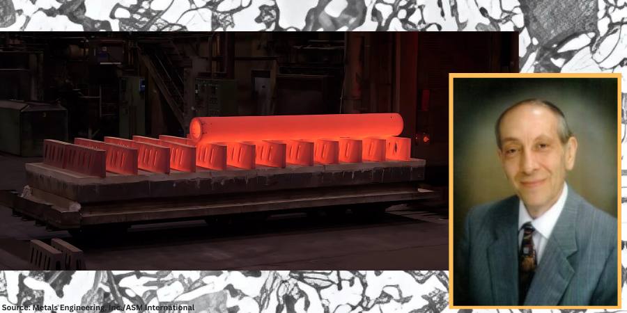
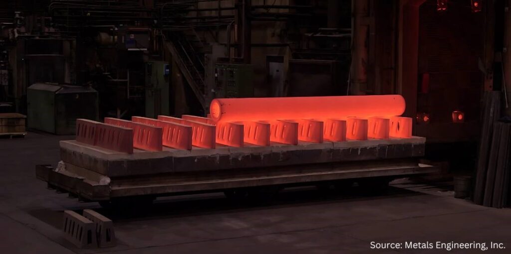
Large paper roll normalized in a car bottom furnace and cooled (due to its mass) using the assistance of a floor fan.
Soak periods for normalizing are typically one hour per inch of cross-sectional area but not less than two hours at temperature. It is important to remember that the mass of the part or the workload can have a significant influence on the cooling rate and thus on the final microstructure. Thin pieces cool faster and are harder after normalizing than thicker ones. By contrast, after furnace cooling in an annealing process, the hardness of the thin and thicker sections is usually about the same.
Micrograph of medium-carbon AISI/SAE 1040 steel showing ferrite grains (white etching constituent) and pearlite (dark etching constituent). Etched in 4% picral followed by 2% nital. (Bramfitt and Benscoter, 2002, p. 4. Reprinted with permission of ASM International. All rights reserved.)
When people think of normalizing, they often relate it to a microstructure consisting primarily of pearlite and ferrite. However, normalized microstructures can vary and combinations of ferrite, pearlite, bainite, and even martensite for a given alloy grade are not uncommon. The resultant microstructure depends on a multitude of factors including, but not limited to, material composition, part geometry, part section size, part mass, and cooling rate (affected by multiple factors). It is important to remember that the microstructure achieved by any given process sequence may or may not be desirable depending on the design and function of the component part.
The microstructures produced by normalizing can be predicted using appropriate continuous cooling transformation diagrams and this will be the subject of a subsequent “Ask The Heat Treat Doctor” column.
In this writer’s eyes, industry best practice would be to specify the desired microstructure, hardness, and mechanical properties resulting from the normalizing operation. Process parameters can then be established, and testing performed (initially and over time) to confirm/verify results.
In many cases, the failure of the normalizing process to achieve the desired outcome centers around the lack of specificity (e.g., engineering drawing requirements, metallurgical and mechanical property call outs, testing/verification practices, and quality assurance measures). Failure to specify the required microstructure and mechanical properties/characteristics can lead to assumptions on the part of the heat treater, which may or may not influence the end result.
“Normalizing is the heat treatment that is produced by austenitizing and air cooling, to produce uniform, fine ferrite/pearlite microstructures in steel … In light sections, especially in alloy hardenable steels, air cooling may be rapid enough to form bainite or martensite instead of ferrite and pearlite.”
What Is Normalizing?
The normalizing process is often characterized in the following way: “Properly normalized parts follow several simple guidelines, which include heating uniformly to temperature and to a temperature high enough to ensure complete transformation to austenite; soaking at austenitizing temperature long enough to achieve uniform temperature throughout the part mass; and cooling in a uniform manner, typically in still air” (Herring, 2014).
It is also important to remember that normalizing is a long-established heat treatment practice. As far back as 1935, Grossmann and Bain wrote:
Normalizing is the name applied to a heat treatment in which the steel is heated above its critical range (that is, heated to make it wholly austenitic) and is then allowed to cool in air.
Since this is one specific form of heat treatment, it will be realized that the structure and mechanical properties resulting from the normalizing treatment will depend not only on the precise composition of the steel but also on the precise way in which the cooling is carried out.
The term ‘normalizing’ is generally applied to any cooling ‘in air.’ But in reality, this may cover a wide range of cooling conditions, from a single small bar cooled in air (which is fairly rapid cooling) to that of a large number of forgings piled together on a forge shop floor … which is a rather slow cool, approaching an anneal. The resulting properties in the two cases are quite different.
In plain carbon steels and in steel having a small alloy content, the air-cooled (normalized) structure is usually pearlite and ferrite or pearlite alone … More rapid cooling gives fine pearlite, which is harder; slow cooling gives coarse pearlite, which is soft. In some few alloy steels, the normalized structure in part may be bainite.
The hardness of normalized steels will usually range from about 150 to 350 Brinell (10 to 35 Rockwell C), depending on the size of the piece, its composition and hardening characteristics.
Importance of Defining Cooling Rate
In 2005, Krauss underscored the importance of defining cooling rate when he wrote: “Air cooling associated with normalizing produces a range of cooling rates depending on section size [and to some extent, load mass]. Heavier sections [and large loads] air cool at much lower cooling rates than do light sections because of the added time required for thermal conductivity to lower temperatures of central portions of the workpiece.”
Microstructures Created by Normalizing
The microstructural constituents produced by normalizing for a particular steel grade can be ferrite, pearlite, bainite, or martensite. The desired microstructure from normalizing adds an important cautionary note, as addressed by Krauss in STEELS (1990 and 2005), namely: “Normalizing is the heat treatment that is produced by austenitizing and air cooling, to produce uniform, fine ferrite/pearlite microstructures in steel … In light sections, especially in alloy hardenable steels, air cooling may be rapid enough to form bainite or martensite instead of ferrite and pearlite.”
Next time: We define a “still air” cool and look at the state of normalizing in North America.
Practical Data for Metallurgists, 17th ed. TimkenSteel.
Totten, George E., ed. Steel Heat Treatment Handbook, vol. 2, 2nd ed., CRC Press, 2007. 612-613.
About the Author
Dan Herring “The Heat Treat Doctor” The HERRING GROUP, Inc.
Dan Herring has been in the industry for over 50 years and has gained vast experience in fields that include materials science, engineering, metallurgy, new product research, and many other areas. He is the author of six books and over 700 technical articles.
Heat treating aluminum presents a unique concern due to the operating conditions of high temperature, chemical corrosion, mechanical abrasion, and temperature variation. Guest columnist Roger M. Smith, director of technical services at Plibrico Company, LLC, examines the critical role the refractory lining plays in the success of manufacturing aluminum, why a refractory is susceptible to cracking under extreme conditions, and how to select and prepare refractory linings to achieve a longer service life.
A significant concern when manufacturing aluminum metal is the practical service life of the furnace. The service life is driven by the refractory lining’s ability to resist the various operating conditions within the furnace, such as high temperature, temperature variation, chemical corrosion, and mechanical abrasion. Ideally, a single refractory composition would be capable of withstanding all these conditions and readily available at a low price. Unfortunately, this is rarely the case.
Proper refractory selection is often about finding the best balance between price, properties, and performance for the given application and operating conditions. A refractory capable of high strength and abrasion resistance is often susceptible to cracking caused by extreme temperature variations, commonly referred to as thermal shock. However, a material capable of withstanding thermal shock without catastrophic cracking may be vulnerable to chemical corrosion. Finding the best balance of material properties for each zone in each furnace is important for maximizing the service life of a furnace.
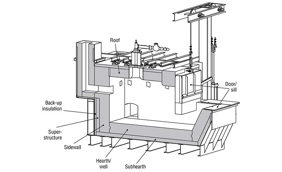
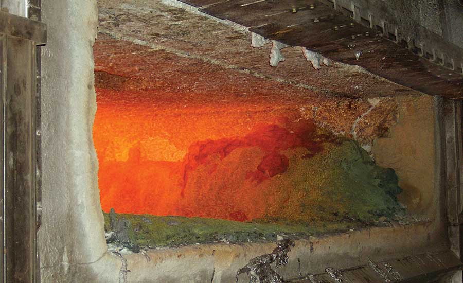
Figure 1. Schematic showing refractory lining in an aluminum furnace
Refractory Under Attack — Requirements for Melting Aluminum
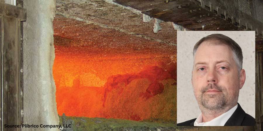
The refractory lining in an aluminum furnace (Figure 1) must endure various chemical reactions that occur while the furnace is in operation. There are three separate regions to consider: above, below, and at the melt line. Above the melt line, the refractory must withstand attack from various alkali vapors. Alkali vapors can be produced from flux used in the aluminum and from the combustion products used to heat the furnace. Below the melt line, the refractory must withstand molten aluminum. At the melt line, the region commonly referred to as the bellyband area, there is a triple point where the refractory, atmosphere, and aluminum interact.
The refractory below the melt line comes in direct contact with liquid aluminum when the furnace is in operation. This contact can create a chemical reaction zone where oxides on the surface of the refractory can be reduced, such as silica (SiO2) to form silicon. Conversely, aluminum can penetrate into the refractory lining either through the same redox reactions or through infiltration due to capillary forces.
Aluminum forms corundum (Al2O3) when it oxidizes. This results in a change of the crystal structure from face-centered cubic to hexagonal, which causes a significant volume expansion. When corundum is formed inside the refractory lining, the change in volume creates cracks, which lead to more infiltration and more cracks until the refractory lining ultimately fails.
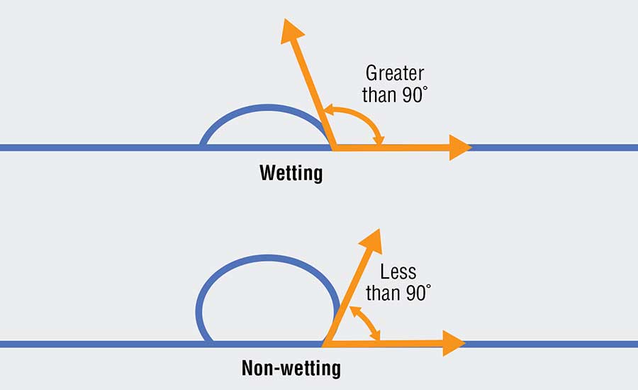
Wetting the Refractory
One method for reducing the reaction zone is to prevent the aluminum from “wetting” the refractory (see Figure 2). A liquid’s ability to “wet” a surface is defined by the contact angle of the liquid. When the contact angle between the liquid and the surface is greater than 90 degrees, then the liquid is said to wet the surface. When the contact angle is less than 90 degrees, the liquid does not wet the surface. A liquid that does not wet the surface is analogous to water beading on a car that has been freshly waxed. When aluminum does not wet a refractory, it is not able to react with the refractory and is not able to penetrate the lining.
Figure 2. Contact angle of the liquid demonstrating wetting vs. non-wetting
Various additives can be used to reduce aluminum’s tendency to wet a refractory. Some of the most used additives include barium, boron, or fluoride. They modify the surface chemistry of the refractory and reduce aluminum’s ability to react and penetrate. Using additives such as these greatly extends the effective service life of a refractory lining.
While non-wetting additives can be beneficial to extending the service life in areas where there is contact with molten aluminum, there are no benefits when not in aluminum contact. They do not protect from alkali attacks above the melt line. They do not enhance the abrasion resistance of the material. They do not improve the thermal shock resistance of the material. Furthermore, these additives are volatile. When exposed to temperatures above 1700°F (927°C), they begin to lose their effectiveness because they chemically react with other materials in the refractory and change. The additives can also be costly, which raises the price of the refractory compared to one with the same composition but without the additive.
The presence of non-wetting additives can have some negative effects on a refractory. Tests have shown that a 1% addition of a fluoride additive in a conventional castable can reduce the hot modulus of rupture (HMOR) by as much as 30% at 2000°F (1093°C). The effect can be even more significant in a low-cement castable. The loss in hot strength is likely attributed to the formation of a glassy phase induced by the additive. Fluoride and boron are both well-known glass formers and will form a glassy phase at the grain boundaries at high temperatures, which reduces the bond strength between individual grains and the overall strength of the bulk material.
Figure 3. Refractory lining
Balancing Refractory Properties
The advantages and disadvantages of a refractory material should be considered when selecting materials for an aluminum furnace. The sidewalls of a furnace all come in direct contact with molten aluminum.
The upper sidewalls must be scraped to remove aluminum that splashes up to prevent corundum growth. The refractory selected for its sidewalls should be abrasion resistant to protect from mechanical scraping and non-wetting to protect from corundum growth. The hearth and well are submerged in aluminum, but they do not see the same level of abrasion as the sidewalls. The sub-hearth may see some molten aluminum but must also provide support, so a strong, non-wetting refractory should be used.
The door and sill will experience temperature fluctuations every time the door is opened, and they will be exposed to abrasion as the furnace is charged. Materials that are resistant to thermal shock and abrasion should be selected. The roof and superstructure need to be strong and resistant to alkali vapors. Backup insulation should be selected to reduce heat loss, but it should be of a composition that has moderate resistance to molten aluminum in case of refractory failure at the hot face.
In all these zones, the operating conditions of the specific furnace must be considered, and the balance of properties must be adjusted case-by-case. The primary failure modes must be identified, and materials should then be adjusted accordingly.
The Key to Refractory Selection
The operating conditions in an aluminum furnace require a refractory lining with different benefits in different zones. At the furnace door, the refractory can experience drastic fluctuations in temperature that can cause cracking. The upper sidewalls will develop scale that has to be scraped off, so the refractory needs to be abrasion resistant.
The lower sidewalls come in direct contact with molten aluminum and need to resist chemical attacks and aluminum penetration to avoid corundum growth. Finding a cost-effective refractory that can meet all these requirements is very difficult, but it can be done with sufficient research. Careful material selection that considers the needs and operating conditions of a particular furnace is important for maximizing the service life of a refractory lining.
About the Author:
Roger M. Smith Director of Technical Services Plibrico Company, LLC Source: Plibrico
Roger Smith is a seasoned professional in the refractory industry. With a master’s degree in Ceramic Engineering from the University of Missouri – Rolla, Roger has over 15 years of experience in the processing, development, and quality assurance of both traditional and advanced ceramics. He has a proven track record in developing innovative ceramic formulations, scaling up processes for commercial production, and optimizing manufacturing operations.
The need to understand how certain furnace designs operate comes at a time when heat treaters are weighing each energy cost and benefit of their systems and processes. Read on for a quick summary on how dual chamber furnaces preserve energy.
On April 17-19, 2024, TAV VACUUM FURNACES provided a speaker at the 4th MCHTSE (Mediterranean Conference on Heat Treatment and Surface Engineering). The speech focused on the energy aspects of vacuum heat treatment, a subject towards which all of us within the industry need to pay attention for reducing the carbon emissions aiming at a zero net emissions future.
We have already analyzed the essential role that vacuum furnaces will play in this transition, with a focus on the optimization of energy consumption in our previous article. With this new presentation, we wanted to emphasize how selecting the right vacuum furnace configuration for specific processes may impact the energy required to perform such process. For doing so, we compared two different furnace designs — single chamber vs. dual chamber vacuum furnaces — detailing all of the components’ energy consumption for a specific process.
TAV DC4, dual chamber vacuum furnace for low pressure carburizing and gas quenching Source: TAV VACUUM FURNACES
As a sneak peek into our presentation, we will summarize below how the main features of the two vacuum furnaces design are affecting their energy performance.
Let’s start by introducing the protagonist of our comparison: a single chamber, graphite insulated vacuum furnace, model TAV H4, and a dual chamber furnace TAV DC4, both having useful volume 400 x 400 x 600 mm (16” x 16” x 24”) (w x h x d).
In a single chamber vacuum furnace, like the TAV H4, the entire process is carried out with the load inside the furnace hot zone. This represents a highly flexible configuration that can perform complex heat treatment recipes with a multiple sequence of heating and cooling stages and to precisely control the temperature gradients at each stage.
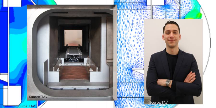
Configuration of the TAV DC4 dual chamber vacuum furnace Source: TAV VACUUM FURNACES
Alternatively, a dual chamber vacuum furnace, like the TAV DC4, is equipped with a cold chamber, separated from the hot zone, dedicated for quenching. Despite the greater complexity of this type of vacuum furnace, the dual chamber configuration allows for several benefits.
First, in dual chamber furnaces, the graphite insulated hot chamber is never exposed to ambient air during loading and unloading of the furnace; for this reason, the hot chamber may be pre-heated at the treatment temperature (or at a lower temperature, to control the heating gradient). But in single chamber vacuum furnaces, the hot zone must always be loaded and unloaded at room temperature to avoid damages due to heat exposure of graphite to oxygen.
Because dual chamber furnaces have more controlled heating, this will result in both faster heating cycles and lower energy consumption, as a substantial amount of energy is required to heat up the furnace hot zone. This advantage obviously will be more relevant in terms of energy savings the shorter the time is between subsequent heat treatments.
View of the cold chamber of the TAV DC4 dual chamber vacuum furnace Source: TAV VACUUM FURNACES
Secondly, since the quenching phase is performed in a separated chamber, the hot zone insulation can be improved in dual chamber vacuum furnaces by increasing the thickness of the graphite board without compromising cooling performance. This translates into a significantly lower heat dissipation, to the extent that at 2012°F (1100°C) the power dissipation per surface unit (kW/m2) is reduced by 25% compared to an equivalent single chamber vacuum furnace.
Additionally, quenching in a dedicated cold chamber allows to obtain higher heat transfer coefficients and higher cooling rates compared to a single chamber vacuum furnace. Since the cold chamber is dedicated solely to the quenching phase, it can be designed for optimizing the cooling gas flow only without the need to accommodate all the components required for heating. All things considered, the heat transfer coefficient achievable in the TAV DC4 can be, all other things being equal, even 50% higher compared to a single chamber vacuum furnace. Secondly, since the cold chamber remains at room temperature throughout the whole process, only the load and loading fixtures need to be cooled down; as a result, the amount of heat that needs to be dissipated is significantly less compared to the single chamber counterpart.
CFD simulation showing a study on the cooling gas speed in a section of the cooling chamber for the TAV DC4 dual chamber vacuum furnace Source: TAV VACUUM FURNACES
For heat treatments requiring high cooling rates, it is possible to process significantly higher loads on the dual chamber furnace compared to the single chamber model; translated into numbers, the dual chamber model can effectively quench as much as double processable in a single chamber furnace, depending on the alloy grade, load configuration and overall process. The savings in terms of energy consumption per unit load (kWh/kg) achievable in the dual chamber furnace for such processes can be as high as 50% compared to the single chamber furnace.
In the end, the aim of the speech was to highlight how the energy efficiency of vacuum furnaces is highly dependent on the machine-process combination. Choosing the right vacuum furnace configuration for a specific application, instead of relying solely on standardised solutions, will improve significantly the energy efficiency of the heat treatment process and drive the return on investment.
About the Author
Giorgio Valseccchi R&D Manager TAV VACUUM FURNACES
Giogio Valsecchi has been with the company TAV VACUUM FURNACES for nearly 4 years, after having studied mechanical engineering at Politecnico di Milano.