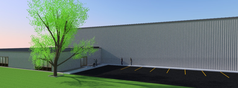
A rendering of McLaughlin Furnace Group’s new facility in Avilla
A heat treating equipment manufacturer in Fort Wayne, Indiana, recently broke ground on an expansion that will nearly triple the size of its existing facility.
McLaughlin Furnace Group celebrated the groundbreaking at its new site in Avilla, Indiana, in a new industrial park north of Fort Wayne. The $3 million expansion, from 17,500 sq ft to 50,000 sq ft, will allow more space for the company to design and manufacture atmosphere and vacuum processing furnace products, including car-bottom furnaces, nitriding furnaces, temper furnaces, and endothermic gas generators.
This article continues the ongoing discussion on Equipment Selection for Induction Hardening by Dr. Valery Rudnev, FASM, IFHTSE Fellow. Six previous installments in Dr. Rudnev’s series on equipment selection addressed selected aspects of scan hardening and continuous/progressive hardening systems. This post is the second in a discussion on equipment selection for one of four popular induction hardening techniques focusing on single-shot hardening systems.
The first part on equipment selection for single-shot hardening is here; the third part is here. To see the earlier articles in the Induction Hardening series at Heat TreatToday as well as other news about Dr. Rudnev, click here.
Traditional Designs of Single-Shot Inductors
Figure 1 shows a typical shaft-like component (Figure 1,top-left) suitable for a single-shot hardening inductor, as well as a variety of traditionally designed single-shot inductors for surface hardening shaft-like workpieces. Sometimes, these inductors are also referred to as channel inductors.
A conventional single-shot inductor consists of two legs and two crossover segments, also known as bridges, “horseshoes,” or half-loops [1]. The induced eddy currents under the legs primarily flow along the length of the part (longitudinally/axially) with the exception of the regions of the workpiece located under the crossover segments where the flow of the eddy current is half circumferential. Unlike scanning inductors, traditional designs of single-shot inductors can be quite complicated.
Figure 1. A typical shaft-like component (top-left image) suitable for a single-shot hardening and a variety of traditionally designed single-shot inductors for surface hardening shaft-like workpieces (Courtesy of Inductoheat Inc., an Inductotherm Group company)
With a predominantly longitudinal eddy current flow, the heat uniformity in the diameter change areas of the stepped shafts is dramatically improved and the tendency of corners and shoulders to be overheated is reduced significantly compared to applying a single-turn or multi-turn solenoid coils commonly used in scan hardening and continuous/progressive hardening.
Because the copper of single-shot inductors does not completely encircle the entire region required to be heated, rotation must be used to create a sufficiently uniform austenitized surface layer along the workpiece perimeter. Upon quenching, a sufficiently uniform hardness case depth along the circumference of the part will be produced. For single-shot inductors, the rotation speed usually ranges from 120 to 500 rpm.
Different types of magnetic flux concentrators (also called flux intensifiers, flux controllers, flux diverters, magnetic shunts, etc.) complement the copper profiling of an inductor, helping to achieve the required hardness pattern. Flux concentrators may provide several considerable benefits when applied in single-shot inductors. This includes an increase of coil electrical efficiency, a noticeable reduction of coil current, and a significant reduction of the external magnetic field exposure.
As an example, Figure 2 shows a transverse cross-section of a single-shot inductor and a straight shaft. Computer-modeled electromagnetic field distribution of a bare inductor (Figure 2, left) compared to an inductor with a U-shaped flux concentrator (Figure 2, right) is shown. Note that the magnitude of magnetic field intensity on both images is different. The use of U-shaped magnetic flux concentrators in single-shot hardening applications typically results in a 16% to 27% coil current reduction compared to using a bare inductor while having a similar heating effect. A reduction of the external magnetic field exposure while applying flux concentrator is even more dramatic (Figure 2, right).
Figure 2. Computer-modeled EMF distribution in the transverse cross-section of a bare inductor (left) compared to an inductor with U-shaped flux concentrator (right). Note: the scale of magnetic field intensity on both images is different [1].Different applications may call for various materials used to fabricate magnetic flux concentrators including stacks of silicon-steel laminations, pure ferrites, and various proprietary multiphase composites. The selection of a particular material depends on a number of factors, including the following [1]:
applied frequency, power density, and duty cycle;
operating temperature and ability to be cooled;
geometries of workpiece and inductor;
machinability, formability, structural homogeneity, and integrity;
an ability to withstand an aggressive working environment resisting chemical attack by quenchants and corrosion;
brittleness, density, and ability to withstand occasional impact force;
ease of installation and removal, available space for installation, and so on.
It should be noted that, though in most single-shot hardening applications flux concentrators will improve efficiency, there are other cases where no improvement will be recorded, or efficiency may even drop. A detailed discussion regarding the subtleties of using magnetic flux concentrators is provided in [See References 1, 2.].
Sufficient rotation is critical when using any single-shot inductor design. As an example, Figure 3 shows the sketch of a single-shot induction hardening system.
Figure 3. Sketch of single-shot induction hardening of an axle shaft. Note: The right half of this induction system is computer-modeled in Fig. 4 [3].Taking advantage of symmetry, only the right side of such a system was modeled using finite-element analysis. Figure 4 shows the result of computer simulation of initial, interim, and final heating stages, taking into consideration the shaft rotation. Insufficient part rotation resulted in a non-uniform temperature distribution along the shaft perimeter (Figure 4, left). Proper shaft rotation results in a sufficiently uniform temperature pattern (Figure 4, right).
Figure 4. Results of numerical simulation of heating an axle shaft by using a single-shot inductor [3].There should be at least eight full rotations per heat cycle (preferably more than 12 rotations), depending on the size of the workpiece and the design specifics of the inductor, though, as always in life, there are some exceptions. Shorter heating times and narrower coil copper heating faces require faster rotation during the austenitization cycle.
An appropriate inductor design with a closely controlled and monitored rotation speed will produce a hardness pattern with minimum circumferential and longitudinal temperature deviations, which will result in sufficiently uniform hardness patterns (Figure 5, left four images). Failure to ensure proper rotation as well as the use of worn centers (lacking grabbing force resulting in slippage and excessive part wobbling) could lead to an unacceptable heat non-uniformity, severe local overheating, and even melting (Figure 5, right). Manufacturers of induction equipment such as Inductoheat have developed various proprietary tools, holders, fixtures, and monitoring devices to ensure proper rotation and high quality of single-shot hardened parts.
Figure 5. Inductor design with closely controlled rotation speed will produce a hardness pattern with minimum circumferential temperature deviations (left four images). Failure to ensure proper rotation speed as well as the use of worn centers (lacking grabbing force resulting in slippage) could lead to unacceptable heat non-uniformity and can even cause a localized melting (right image).
The next installment of this column, "Dr. Valery Rudnev on . . . ", will continue the discussion of design features of induction single-shot hardening systems.
A manufacturer of custom industrial chillers based in Houston, Texas, recently purchased a controlled atmosphere brazing (CAB) furnace line to conduct in-house furnace brazing of the company’s heat exchangers.
The CAB furnace was relocated to Cold Shot Chillers, which designs and manufactures standard and specialized custom industrial chillers for multiple industries, including metal finishing, medical, brewery and winery, laser and welding, and agriculture. SECO/WARWICK states that the CAB furnace, which was originally built for a different OEM, is the largest in North America.
An Ohio manufacturer of processing equipment recently received heat treating upgrades to its facility from a heat treat controls system manufacturer, also in Ohio.
Milacron LLC partnered with Super Systems, Inc., based in Cincinnati, Ohio, to make major upgrades to the heat treating assets at its plastics machinery facility in Mt. Orab, Ohio.
Included in the scope of work were new control cabinets, atmosphere flow panels, SCADA software, and a new ammonia dissociator. The work has been completed for this project.
“We are very happy we chose Super Systems… The quality and workmanship set them apart from others in the industry,” said Jeff Bissantz, project engineer, who led the Milacron team.
The Combat Capabilities Development Command Army Research Laboratory, also known as ARL, recently awarded a 3D engineering and manufacturing company a $15 million contract to create a metal 3D printer that it intends to be the world’s largest, fastest, and most precise.
3D Systems and the National Center for Manufacturing Sciences (NCMS) were awarded funding to create this printer and will partner with ARL and the Advanced Manufacturing, Materials, and Processes (AMMP) Program to advance the leadership and innovation. This printer will impact key supply chains associated with long-range munitions, next-generation combat vehicles, helicopters, and air and missile defense capabilities.
“The Army is increasing readiness by strengthening its relationships and interoperability with business partners, like 3D Systems, who advance warfighter requirements at the best value to the taxpayer,” said Dr. Joseph South, ARL’s program manager for Science of Additive Manufacturing for Next Generation Munitions. “Up until now, powder bed laser 3D printers have been too small, too slow, and too imprecise to produce major ground combat subsystems at scale. Our goal is to tackle this issue head-on with the support of allies and partners who aid the Army in executing security cooperation activities in support of common national interests, and who help enable new capabilities for critical national security supply chains.”
According to the U.S. Army Additive Manufacturing Implementation Plan, the Army has been using additive manufacturing (AM) for two decades to refurbish worn parts and create custom tools. Once developed, the Army will leverage its manufacturing experience by placing the new large-scale systems in its depots and labs. Subsequently, 3D Systems and its partners plan to make the new 3D printer technology available to leading aerospace and defense suppliers for development of futuristic Army platforms.
A domestic steel producer and metals recycler chose Sinton, Texas, as the site for the company’s new electric-arc-furnace (EAF) flat roll steel mill.
Steel Dynamics, Inc., a carbon steel producer which also owns Vulcan Steel Products that services the heat treat industry, recently announced its preferred choice as the Sinton location, 30 miles northwest of the port of Corpus Christi, Texas, because it is strategically located within the targeted Southwest U.S. and Mexico market regions; it’s central to the largest domestic consumption of flat roll Galvalume® and construction painted products; and it provides sufficient acreage to allow customers to locate on-site, providing steel mill volume base-loading opportunities.
Mark D. Millett President and CEO Steel Dynamics, Inc.
“We have been developing a flat roll steel business strategy for this region and Mexico for several years,” said Mark. D. Millett, President and Chief Executive Officer, “and the team is ready to execute. We have extensive experience and a proven track record for successfully constructing and operating EAF steel mills and downstream value-add finishing lines. Our planned new EAF flat roll steel mill will be the most technologically advanced facility existing today.”
A high-temperature vacuum and controlled atmosphere furnace manufacturer recently invested in new equipment for advanced firing capabilities.
Centorr Vacuum Industries recently announced it has added new furnace capabilities to its Applied Technology Center for customer use for process proofing, toll work, and process development runs.
The new furnace is based on Centorr’s successful Super VII platform and will join two smaller System VII furnaces, an induction melting furnace, and a continuous belt furnace already in use.
This newly updated 2nd Generation Super VII design comes with several innovative features to allow the processing of a wide variety of metals, hard metals, ceramics, and carbon/graphite composites. The furnace can be used for low temperature degassing, heat treating, annealing, brazing, and sintering of a variety of materials.
READER QUESTION: Just read your article in regards to system accuracy test. I just had a question that maybe you can help me understand. When applying the correction factor of the test instrument and test sensor, is the correction factor to be used based on the furnace set point (operating temperature) at the time of the test or the recording instrument reading during the test? Any insight is appreciated!
This is a question that comes up often in the pyrometry courses I teach.
The Nadcap Pyrometry Reference Guide, question #6, addresses this question, although from a TUS standpoint. The premise is the same for the SAT process though.
Correction factors applied to any test results (TUS & SAT) should be determined based on the setpoint temperature during testing.
One thing to remember is that you may be testing at a temperature which does not fall directly at a temperature indicated on the test wire/test instrument calibration certificate. In this case, you would have two options;
1) Linear Interpolation
2) Pick the adjacent calibration temperature closest to your setpoint during test.
Either way, you would need to establish if you execute #1 or #2 above and document that in an internal procedure.
READER QUESTION: Thanks for the feedback, I have another concern. I perform an SAT on a refrigeration unit that operates at -20 degrees. My test instrument and test sensor are both calibrated at a low temperature of -20, but sometimes the recording instrument indicates a temp of -21 degrees or so. My operating temperature is -20 (setpoint), but as I stated it might indicate a lower temperature. Is there a possible finding here? Although setpoint is -20, recorder shows -21, which the test instrument/sensor does not cover (calibration point).
Jason Schulze for HTT:
You should be in no danger of a finding. The pyrometry guide states the correction factors are based on setpoint.
We welcome your inquiries to and feedback on Heat Treat Today articles. Submit your questions/comments to editor@heattreattoday.com.
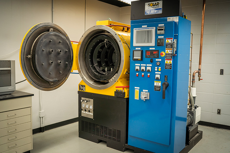
A thermal processing company donated a $300,000 commercial-grade vacuum heat treating and brazing furnace to Lehigh University’s materials science program to help increase opportunities for its students in the field.
The new addition, known as The Mentor®, was donated to Lehigh University by thermal processing company Solar Atmospheres and its CEO and founder, William R. Jones. Its sister company, Solar Manufacturing, designs and builds vacuum furnaces at its location in Souderton, Pennsylvania, just 23 miles from Lehigh’s campus.
Additionally, Solar Atmospheres built and donated a transformer and water-cooling system that was specifically designed for the application.
Wojciech Misiolek, professor and cha ir of the Department of Materials Science and Engineering at the P.C. Rossin College of Engineering and Applied Science
“This is a very powerful, advanced piece of equipment that will allow us to conduct important experiments in our metallurgy teaching and research, especially around additive manufacturing, which is a hot topic these days,” explains Wojciech Misiolek, professor and chair of the Department of Materials Science and Engineering at the P.C. Rossin College of Engineering and Applied Science. “And we will challenge ourselves to use it up to its full capabilities for heat treatment of metals.”
“With this donation,” adds Misiolek, “suddenly you have the industry-grade equipment. It’s not a miniature version, it’s what you will see out in the field. Our educational system at Lehigh is very hands on, and we have a reputation for that. This furnace will increase opportunities for our undergraduate and graduate students and help them hit the ground running when they go into industry.”
Induction heat treaters know that proper coil design is crucial to increasing longevity, improving production quality, and cutting costs. Among the topics addressed in this paper about induction heat treat coil design and fabrication (presented by R. Goldstein, W. Stuehr, and M. Blackby at ASM International) are these:
The design and fabrication of induction heating coils over the years
The Variable of Flow and the Influence of Frequency
Control and Presentation
Structure, Quenching, and Cooling
The paper closes out with a case study using computer simulation to show typical temperature distributions in a single-shot induction hardening coil.
A good place to start whenever preparing parts for induction heat treating is the consideration of inductor design. The authors provide this list (an excerpt):
[spacer color="264C84" icon="Select a Icon"]
Considerations for Inductor Design
Induction heat treating coils are available in many shapes and sizes and must perform a variety of tasks in a given induction heat treating application. Depending on the application, the induction coil design requirements include:
Meet heat treatment specifications in desired production rates
Be robust enough to tolerate manufacturing variations
Mount into the induction machine
Have electrical parameters that match the induction power supply
Deliver quench
Have a satisfactory lifetime
Have satisfactory efficiency
Be repeatable from inductor to inductor
In developing a new induction heat treating coil and process, the first question is whether the component will be produced on an existing system or if a new machine must be built. In many cases, the part producer’s desire is to develop new tooling for an existing machine with spare capacity. This reduces the degree of freedom and can make the induction coil design procedure more complicated because a less-than-optimal frequency or coil style will be necessitated to fit the existing machine (Ref 16).
To determine the ability to use existing equipment, it is necessary to make an analysis of the part to be heat treated. Part material, prior processing, geometry, production rate, and heat treatment specifications all play roles. The part material and prior processing determine what the minimum heat treatment temperature should be, along with how much time is allowed for cooling. The part geometry and heat treatment specifications indicate how much energy is required, what the preferred frequency ranges are, and what type of induction method (i.e., single shot, scanning) is best suited for the application. Finally, the production rate determines how much power and/or how many spindles or stations are required.


![Figure 2. Computer-modeled EMF distribution in the transverse cross-section of a bare inductor (left) compared to an inductor with U-shaped flux concentrator (right). Note: the scale of magnetic field intensity on both images is different [1].](https://www.heattreattoday.com/wp-content/uploads/2019/08/Rudnev-Part-2-Fig-2.jpg)
![Figure 3. Sketch of single-shot induction hardening of an axle shaft. Note: The right half of this induction system is computer-modeled in Fig. 4 [3].](https://www.heattreattoday.com/wp-content/uploads/2019/08/Rudnev-Part-2-Fig-3.jpg)
![Figure 4. Results of numerical simulation of heating an axle shaft by using a single-shot inductor [3].](https://www.heattreattoday.com/wp-content/uploads/2019/08/Rudnev-Part-2-Fig-4.jpg)