10 Steps To Troubleshoot Your Induction System
![]()
 Nikola Tesla said, “If you want to find the secrets of the universe, think in terms of energy, frequency, and vibration.” These three components are evident in getting to know the inner workings of an induction system. When it comes to troubleshooting such a system at in-house heat treat departments, this 10 step guide will help heat treat operators understand the secrets of induction and solve common problems that may arise.
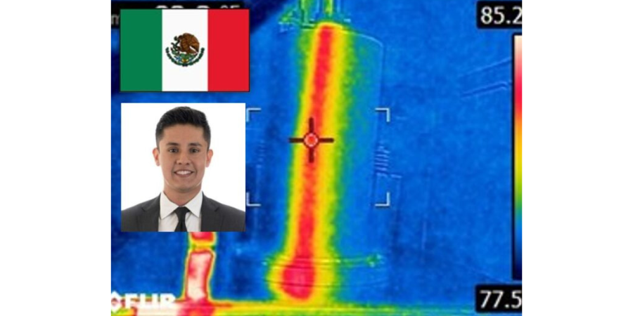
This original content article was first written by Alberto Ramirez, engineer of Power Supply and Automation at Contour Hardening, Inc. and an honoree from Heat Treat Today’s 40 Under 40 Class of 2021, for Heat Treat Today's May 2023 Sustainable Heat Treat Technologies print edition.

Power Supply and Automation Engineer
Contour Hardening, Inc.

Metals can be heated by the process of electromagnetic induction, whereby an alternative magnetic field near the surface of a metallic (or electrically conductive) workpiece induces eddy current (and thus heat) within the workpiece. Induction systems can be complex systems that aim to heat treat specific parts or sections of a mechanical component; depending on the degree of complexity of the part to be treated, it will be the challenge of a professional to detect any problem.
1. Familiarize Yourself with the Process
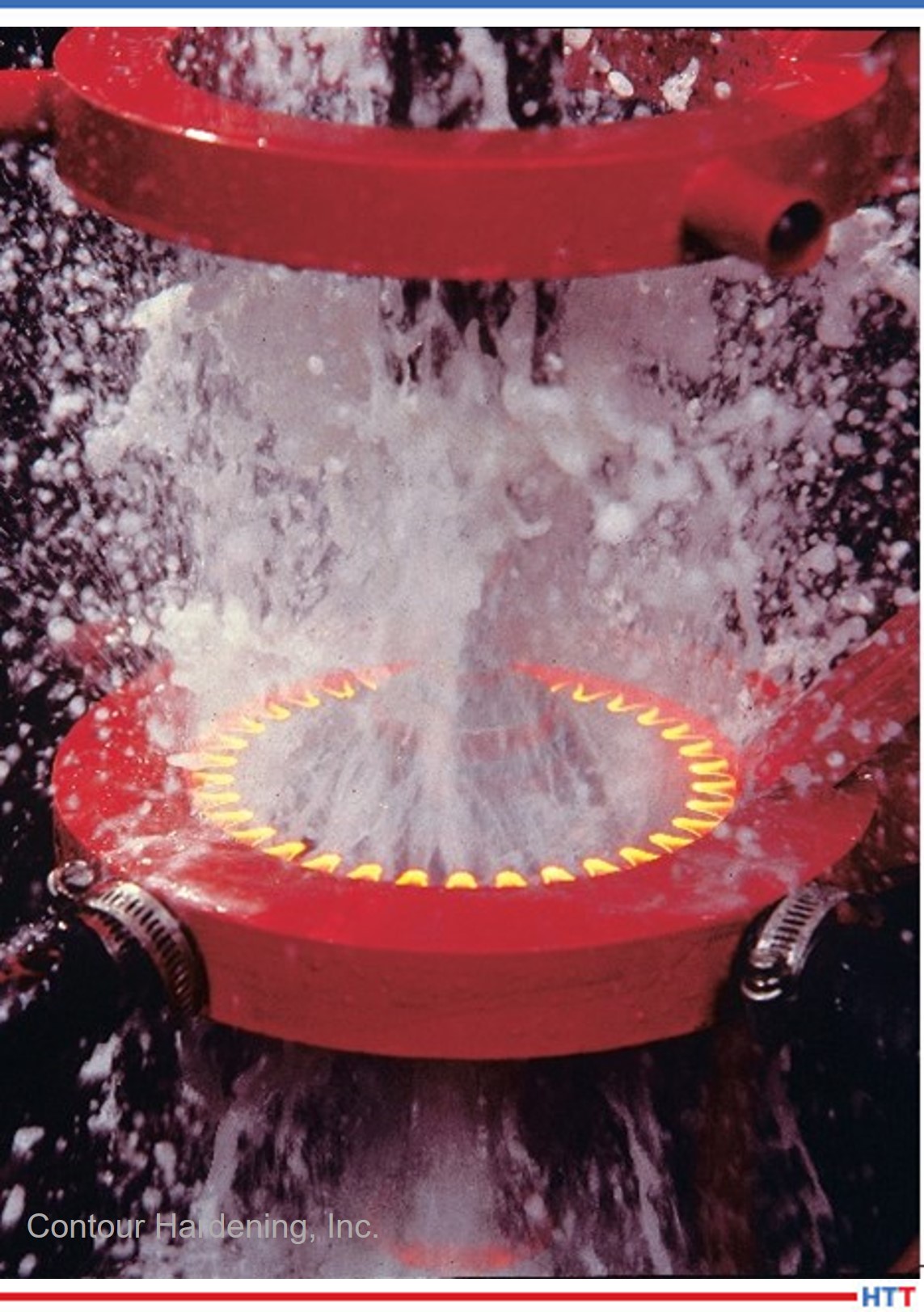
Source: Contour Hardening, Inc.
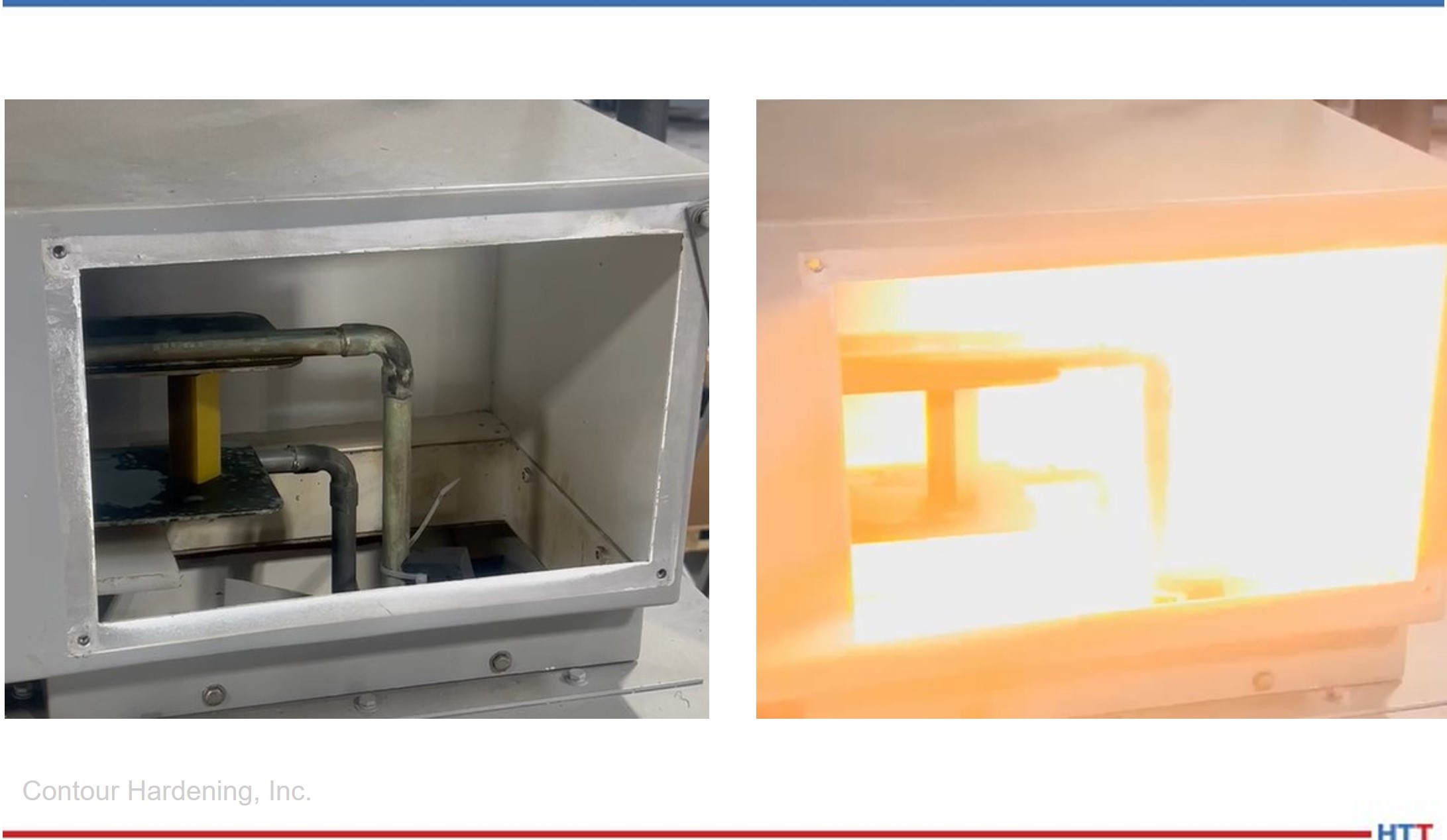
The induction process involves many characteristics such as: position of the piece within the induction coil, load positions, cooling positions, cycle times, applied electric power, and others. It is important that the professional can identify the failure and the particular situation at the moment in which it is occurring.
On some occasions, the failures are not evident and therefore it is essential to analyze the part that has been treated. This analysis can be key to understanding situations such as poor depth due to electrical power or decrease in output frequency, among other possible scenarios.
In addition to the analysis of the piece, it is vital to inspect the “crime scene,” since many of the induction systems — given the nature of the process and the danger involved in handling high electrical potentials — are usually highly automated and the work stations are difficult for staff to access. A good work strategy consists of carefully observing the general conditions of the equipment to determine where the problem will begin to be solved.
2. Identify Main Components and Certain Security Mechanisms of Your Induction System
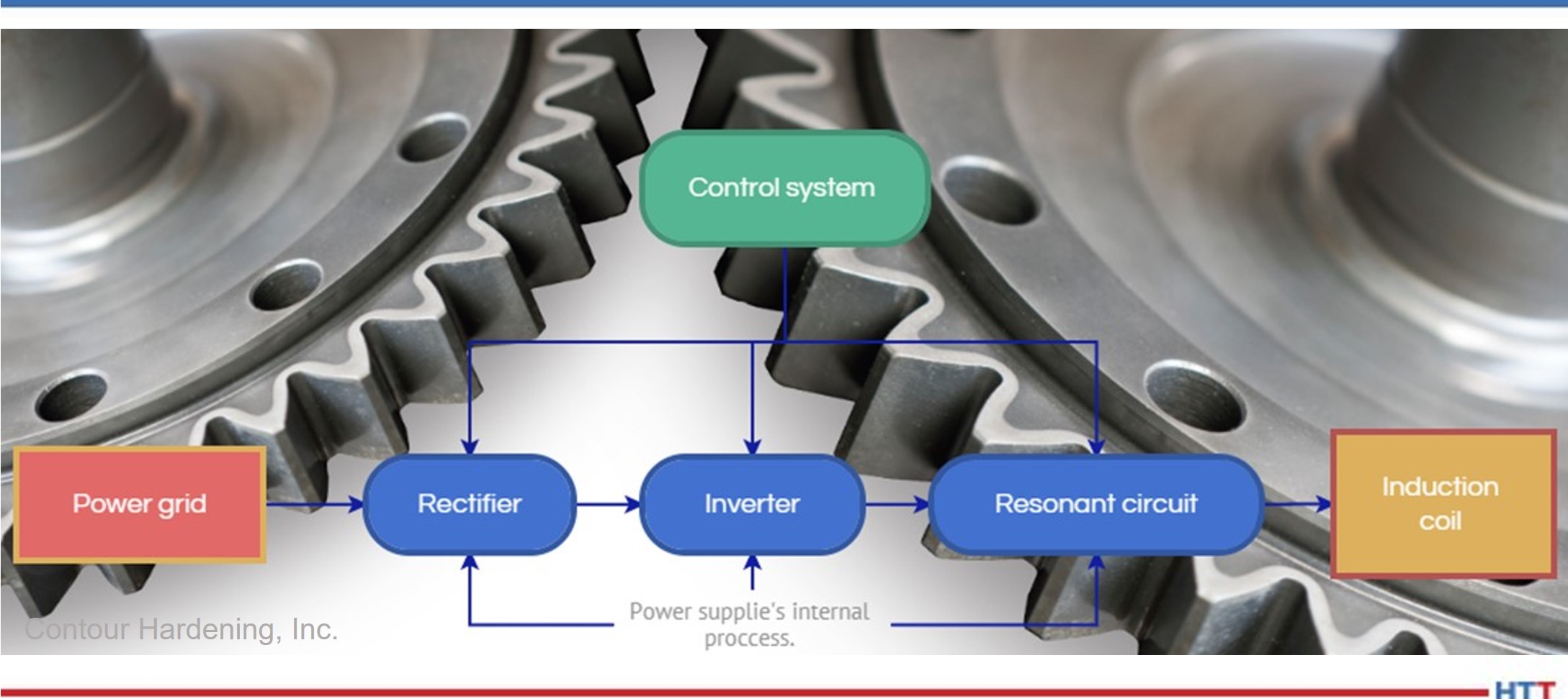
Understanding the interrelationship of the system is important to comprehend which element performs a certain action, as well as the communication channels between them. Once this knowledge is generated, a failure can be associated with a particular component. Induction systems are usually made up of the elements in Figure 2.
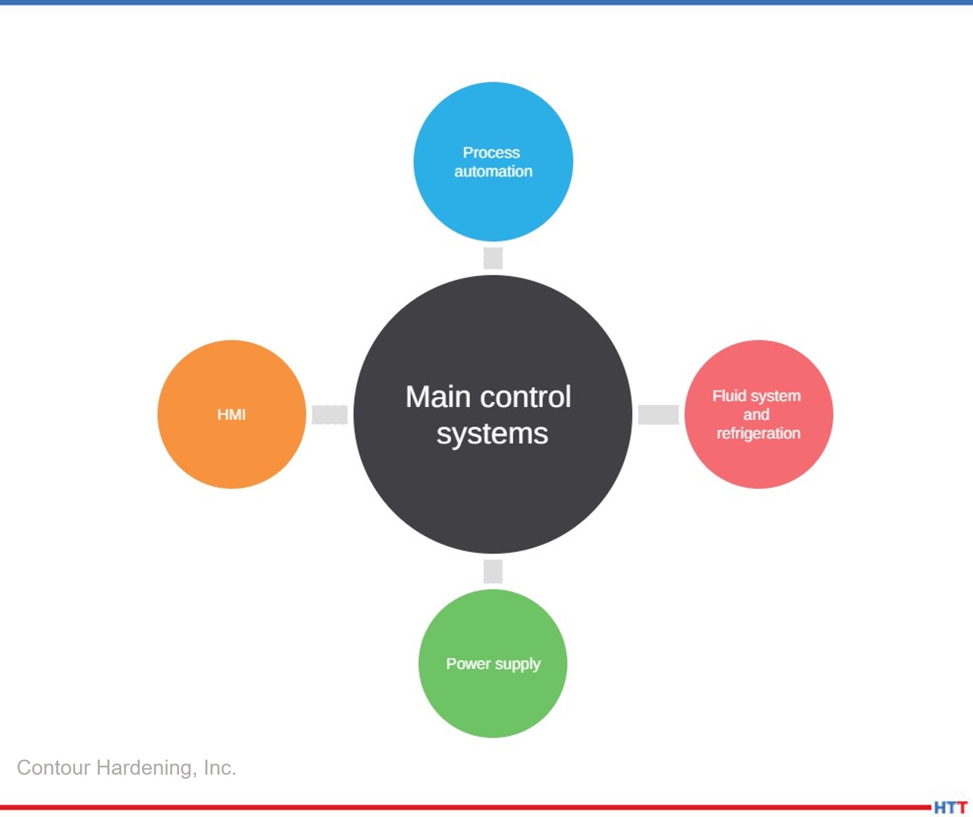
Source: Contour Hardening, Inc.
As we mentioned before, the process involves high electrical potentials, and for this reason, the nature of the power supplies involves power electronic devices such as electrical capacitors, which store energy. Therefore, it is important to electrically discharge the system before beginning to inspect a piece of equipment.
3. Have the Necessary Tools Ready To Carry Out a Good Analysis of the Problem
Source: Contour Hardening, Inc.
Like any technical problem, the use of a mechanical tool is essential when carrying out some type of project, but for the diagnosis of failure in induction equipment it is important to have:
- Oscilloscope
- Function generator
- Ammeter
- Digital and analog multimeter
- High voltage probes
Without these elements it is exceedingly difficult to reach a reliable diagnosis, and the possibility of finding the fault is minimal. Therefore, having these meters in good condition and above all, calibrated, gives a clearer perspective of the problem.
4. Verify that the Process Sensors, Power Monitors, and Induction Coils Are Working Properly
There are different meters that collect information about the process. This information can mostly be viewed through the HMI (human machine interface). On many occasions, a good way to begin to understand the problem is by collecting the information on the process. If these meters do not work correctly, they can lead you to wrong conclusions.
Verify the energy meters are working correctly, as well as your input and output signals.
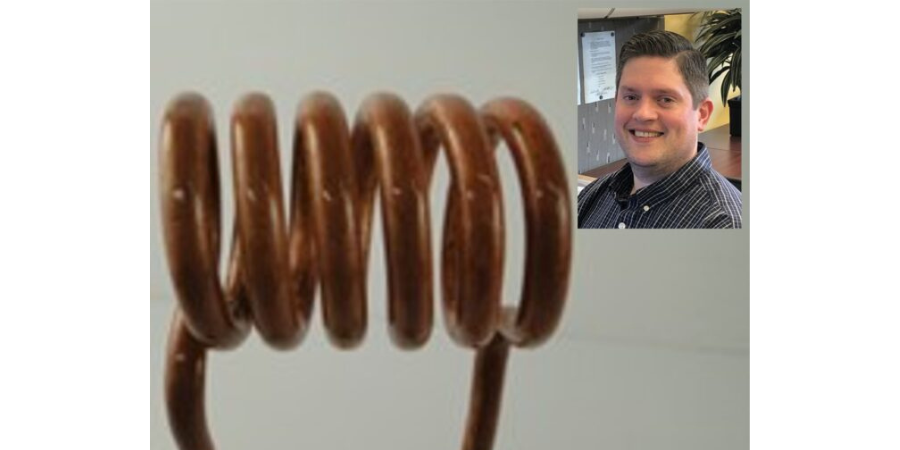
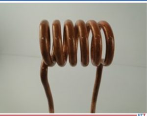
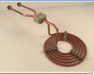
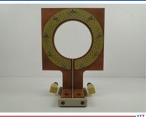
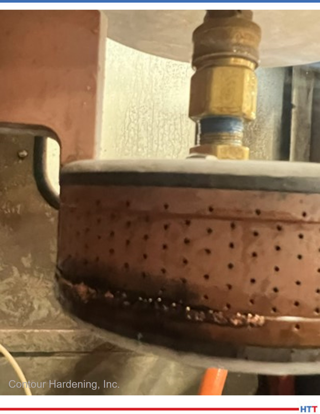
Induction coils are a key element in the induction process since, according to their geometry, they generate the appropriate magnetic fields to achieve the expected metallurgical results. If there are water leaks or the electrical transmission elements are loose or dirty, it could be the root cause of the problem. It is important to start troubleshooting once this circuit is ruled out.
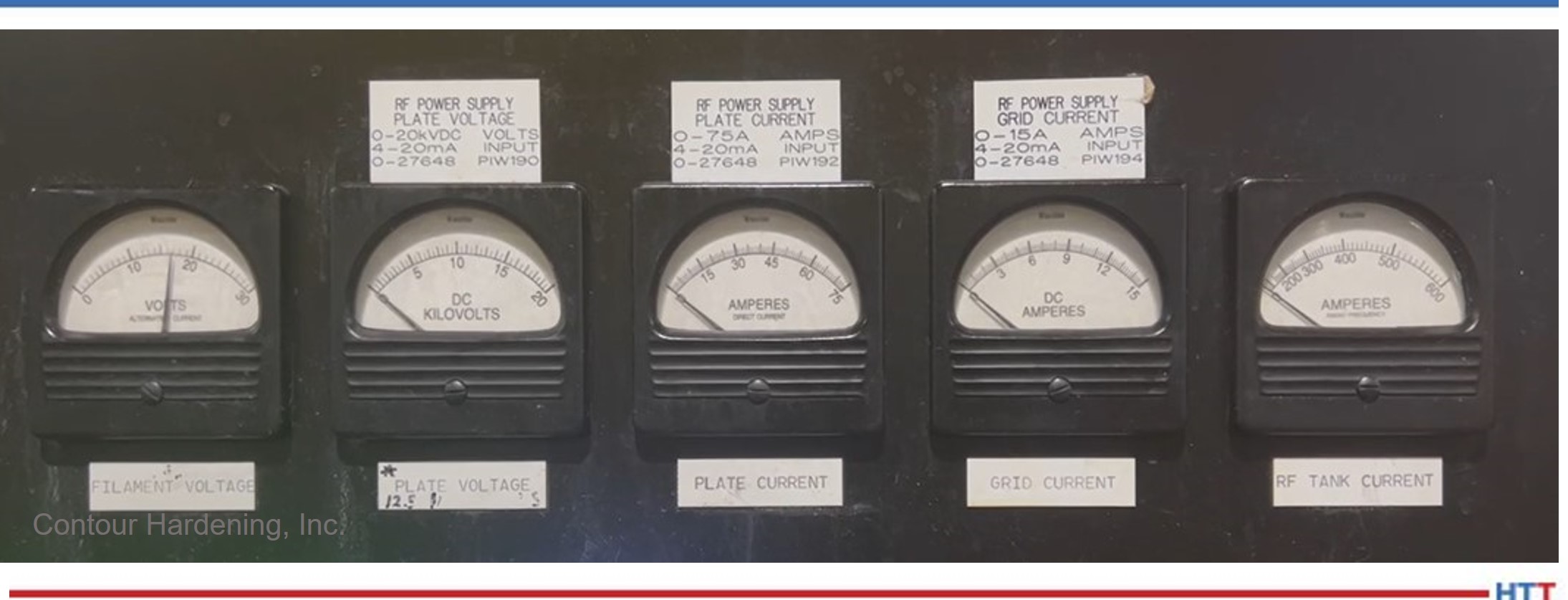
Source: Contour Hardening, Inc.
5. Carry Out Studies of Constant Energy in Your Substation To Identify Possible Problems in Your Energy Supply, Including Critical Times
Electrical energy is the main source in an induction process, power supplies transform and potentiate this resource to create electronic fields strong enough to generate heat in the piece.
Therefore, it is important to find evidence that rules out failures of the electrical system that the induction system is a part of. In the same way, understanding how our electrical system behaves can help us generate behavior patterns that can determine the solution at specific times when it may arise.
6. Document Your Work Methodically and Take One Step at a Time
Induction systems can be very intimidating if you have not had previous experience, and, like any element or situation, it is important to logically approach the problem by analyzing the failure mode, identifying the main parts that interact at that specific moment. From there, document and take small steps, one at a time. If you don’t, it is very likely you will lose all the work you have done, and the situation will get worse.
Source: Contour Hardening, Inc.
If the moves are unsuccessful, you can always return to your starting point and try another approach. The idea is that the failure mode remains the same no matter what moves you make until the problem is resolved. In this way you will have the failure contained, otherwise you could be damaging other elements without realizing it.
It is very important to understand that the processes are sequences that precede and proceed new events. If you understand the process and solve a problem, but now have a new failure, it is important to analyze if this failure is the continuation of the process. If so, it is possible that you find yourself in a case where an event is triggering a series of failures. Therefore, a more in-depth analysis must be carried out. The idea to generate is to get to the root cause and mitigate the risk.
7. Try Any Possibility Related to the Process Regardless of Whether the Relationship Between It and the Problem Is Not Direct
Logical thinking can solve most of the technical failures of a system. For exceptional failures, however, it is necessary to use your imagination and exhaust all possible resources, since the smallest area of interest or the least thoughtful place can be the key to solving a problem.
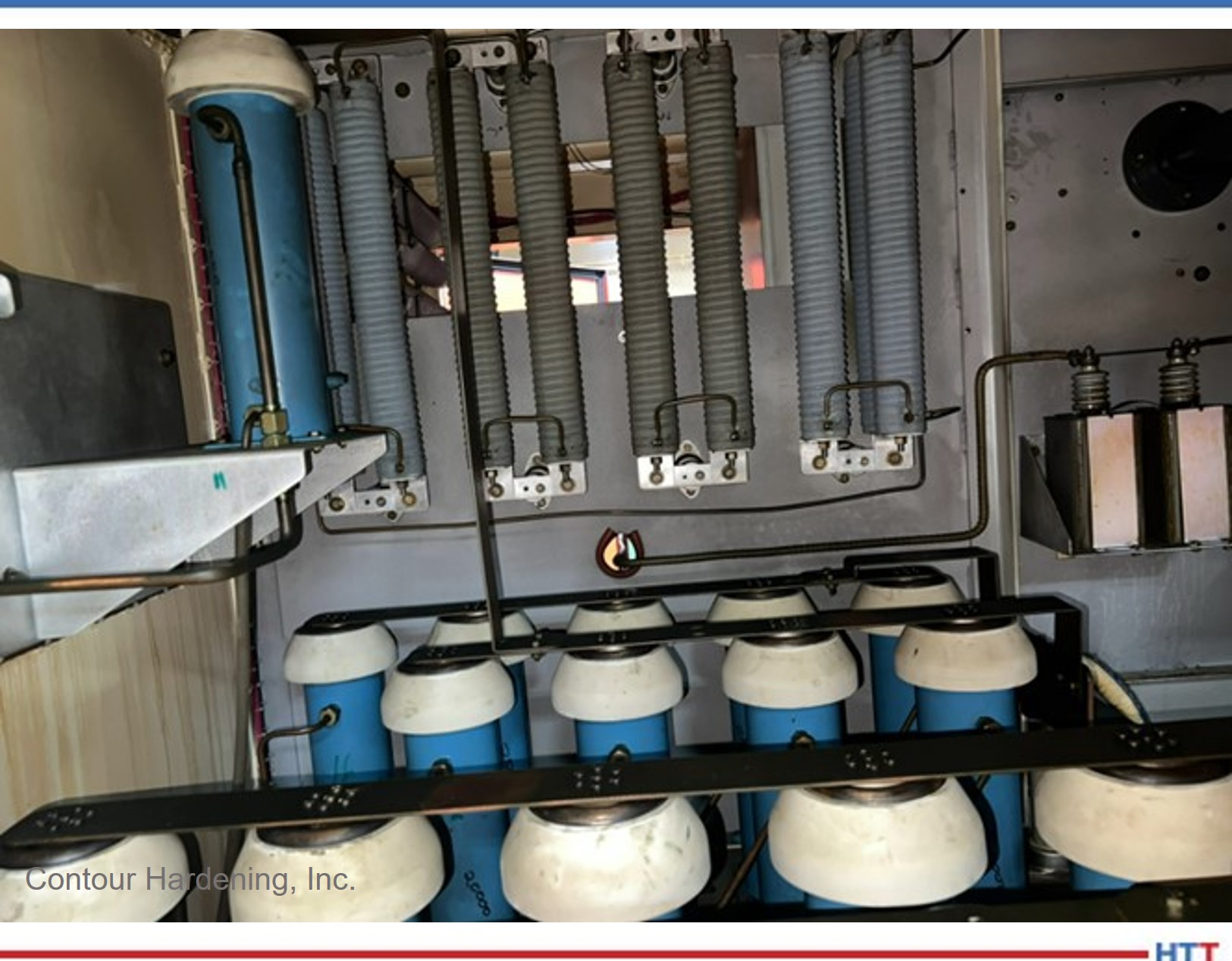
8. Get To Know Your Power Supplies
One of the key factors in any induction equipment is its power supplies. Power supplies are equipment that do not require such arduous maintenance compared to other systems in the industry, but if the minimum maintenance conditions are not present, they can generate high losses for the organization.
Source: Contour Hardening, Inc.
In cases where the problem is the power supplies, it is vital that the same methodical process previously described is followed. Understanding how the energy transformation process works will give you an advantage, as will knowing the elements that compose them or the type of technology used in the rectification process, in the inversion (solid state or electron tubes) and in the resonant circuit. Generally, power supplies follow the transformation in Figure 6.
9. Identify the Critical Parts of Your Induction Equipment and Prepare an Inventory
Contour Hardening, Inc.
Usually, the elements that belong to the power supplies are difficult to obtain depending on the age of your equipment. With the recent microchip crisis in the market, control and automation elements have very long delivery times or the prices are very high. Therefore, it is vital that there is a list of critical parts and an inventory of these.
In addition to the elements described, induction coils are usually very characteristic and important elements in the induction process. These coils are complex elements that have been designed exclusively for the piece, so their manufacture can take several weeks, and the necessary precautions must be taken to maintain a constant maintenance movement.
10. Perform Preventative Measurements to the System To Generate a Pattern of Behavior
Contour Hardening, Inc.
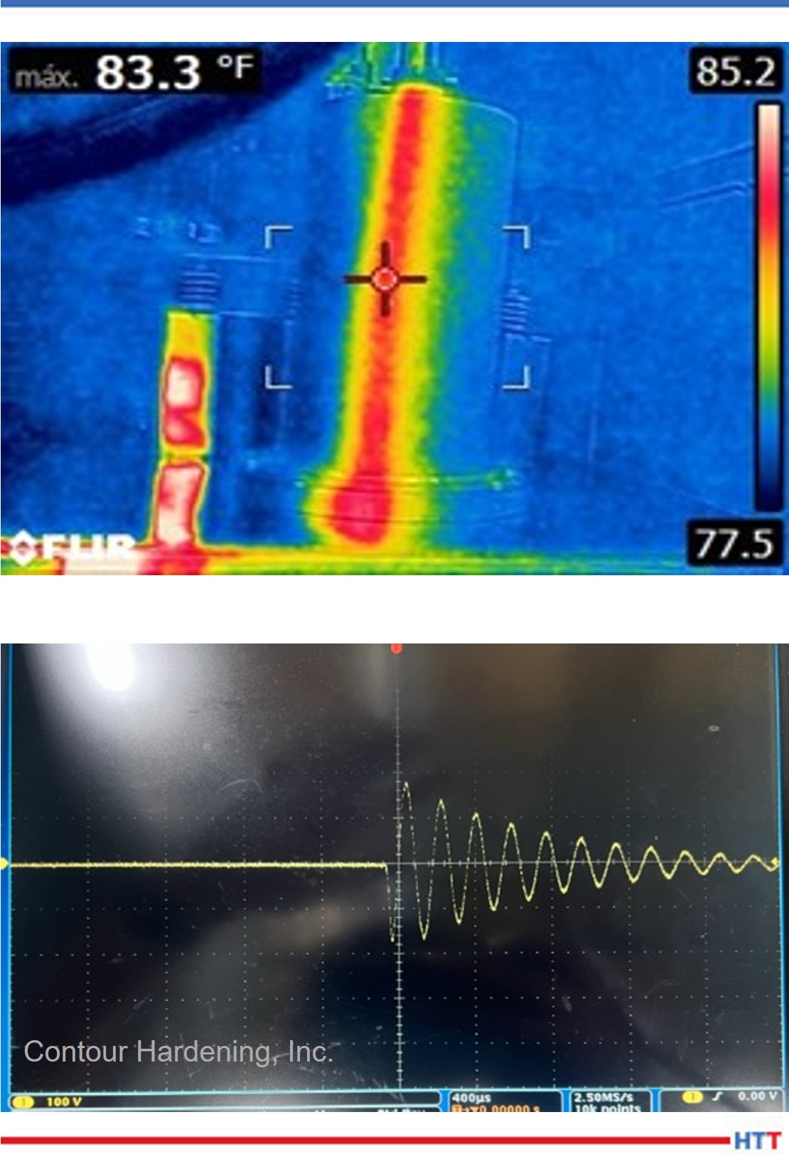
When the system is working in optimal conditions, generate a measurement plan which allows you to generate information on specific points within the system. Once a new failure occurs again you can compare the measurements of failure against those of good performance. Some examples of measurements can be:
- Temperature
- Voltage
- Current
- Resistance and capacitance
- Waveforms
Summary
An orderly and documented work methodology, a good spare parts catalog, and the necessary work tools can be key elements to understand a problem and, more importantly, to solve it effectively.
It is vital that professionals are in continuous training in order to decrease downtime due to failures in induction systems. Training related to metallurgical processes would be a good way to complement your resolution skills by being able to interpret the characteristics of induction systems with the elements that compose it.
References
Valery Rudnev and George Totten, ed., ASM Handbook Volume 4C: Induction Heating and Heat Treatment, (Materials Park, OH: ASM International Heat Treating Society, 2014), 581- 583.
About the Author: Alberto C. Ramirez graduated from the National Technical Institute of Mexico as a mechatronics engineer. He earned his master’s degree in information technology administration from Monterrey Institute of Technology. With more than eight years of experience in power supplies, project management, maintenance, and automation, he currently works as a Power Supply and Automation Engineer at Contour Indianapolis. Alberto began his career at the Contour subsidiary in Mexico and due to his dedication, he is part of the staff in the United States. He is also an honoree from Heat Treat Today's 40 Under 40 Class of 2021.
For more information:
Contact Alberto at Contact Alberto at aramirez@contourhardening.com.
 Find heat treating products and services when you search on Heat Treat Buyers Guide.com
10 Steps To Troubleshoot Your Induction System Read More »