Induction Heating

Induction Heat Treatment & the Role of Simulation Software

Dr. Mihails Scepanskis is the CEO and co-founder of CENOS LLC.

Induction heating is an efficient way to quickly heat electrically conductive metals with pinpoint accuracy. It starts very simply, with a coil of conductive material, however initial design and optimization of the process are very complicated—it's hard to predict power, frequency, and heating time to get necessary results.

Computer simulation for induction heating is a powerful tool that enables engineers to investigate or design a physical system and process using a virtual mathematical model, thus saving time and money on numerous physical design iterations.

Dr. Vadims Geza is the chief scientist at CENOS.

Induction heating computer simulation offers the most efficient means of developing customized and optimized solutions and is, therefore, a necessity—not a luxury—in the modern induction heating industry. In this article, Dr. Mihails Scepanskis and Dr. Vadims Geza, both of CENOS LLC, based in Riga, Latvia, list features and benefits, obstacles and solutions of induction heating; advantages and disadvantages of computer simulation vs physical testing; what should be taken into account when choosing the right simulation software.


How simulation software can help companies save time and money on induction coil and process design

About Induction Heating

Today induction heating is used in many industrial processes, such as heat treatment in metallurgy, crystal growth and zone refining used in the semiconductor industry, and to melt metals which require very high temperatures.

Where Is Induction Heating Used?

  • Automotive
  • Construction
  • Aerospace
  • Metallurgical Plants
  • Oil & Gas Component Manufacturing
  • Special Applications

NASA's experimental NTP fuel elements heated with induction (Photo: CENOS)

Features:

  • Heat generation occurs inside the part.
  • Heating is contactless—as a result, product warpage, distortion and reject rates are minimized.
  • This method can provide very high power densities.
  • Heating may be highly selective in the depth and along the surface.
  • Any processing atmosphere (air, protective gas, vacuum) can be applied.
  • Very high temperatures may be reached.

The general benefits of induction surface heat treatment are

  • Short heating times—production rates can be maximized.
  • Optimized consistency—induction heating eliminates the inconsistencies and quality issues associated with open flame, torch heating, and other methods.
  • Extended fixture life—induction heating delivers heat to very small areas of your part without heating any surrounding parts. This extends the life of the fixturing and mechanical setup.
  • Environmentally sound without burning fossil fuels—induction is a clean, non-polluting process. Improves working conditions for employees by eliminating smoke, waste heat, noxious emissions, and loud noise.
  • Effective energy consumption—this uniquely energy-efficient process converts up to 90% of the energy expended energy into useful heat; batch furnaces are generally only 45% energy-efficient. Requires no warm-up or cool-down cycle.
  • Flexible adaptation to the hardening tasks
  • Closed loop computerized process control and compatibility with overall process automation

Large gear heat treatment (Photo: CENOS)

Obstacles:

  • Initial design and optimization of the process is very complicated.
  • It is hard to predict power, frequency and heating time to get necessary results.
  • Unlike other heating methods, induction heating requires specific coil design for each workpiece, so it's not very economic unless you need to process multiple similar workpieces.

To design and calculate the induction heating process you can:

  • Do a rough analytical estimation, then proceed with countless design iterations in the lab.
  • Find a professional company that can do induction coil and process design for you, but keep in mind that you most likely will be charged for design hours spent in the lab.
  • Buy a sophisticated multi-physics simulation software and hire a trained simulation engineer/analyst or pay for engineer's training (usually takes 3 months).
  • Start using a simple, affordable, and induction heating-focused simulation software like CENOS Platform, which features online training and templates for a quick and easy start.

Induction Heating and Computer Simulation

What Is a Computer Simulation?

Nowadays, in various industries, manufacturers prefer using software simulations over physical testing. Computer simulation is a powerful tool that enables engineers and scientists to investigate or design a physical system and/or process using a virtual mathematical model, thus saving time and money on numerous physical design iterations.

The vast majority of modern computer simulation software packages utilize numerical methods (e.g. finite element method or “FEM”) to evaluate extremely complex physical systems—systems that are otherwise impossible to precisely analyze. By leveraging the power of modern computer hardware, simulation software can provide substantial improvements in the efficiency, reliability, and cost-effectiveness in design and development processes.

Computer Simulation in Induction Industry

  • First works on computer simulation of induction coils were made in the 1960s. Due to limited access to computers, their low memory, speed, and poor programming methods, the computer simulation did not receive significant industrial application until the 1980s.
  • Now computer simulation has become a practical tool for everyday use in the induction industry. It allows the user to design optimal systems, improve equipment performance, dramatically reduce development time and costs, and better understand the process dynamics, etc.
  • Though there are still difficulties in an accurate simulation of non-linear and different mutually coupled tasks, computer simulation is effectively used for the design of induction heating coils and problem solution.

The 10 cm gear hardening with one concentric inductor at 170 kHz and 1.9 kA over 120 ms

Benefits and Value of Induction Heating Computer Simulation

The use of induction heating computer simulation software can promote substantial improvements in the performance and cost-effectiveness of induction heating equipment, in addition to large reductions in the cost and time required to design and develop induction heating processes.

From a design perspective, computer simulation is valuable for a number of reasons, two of the most notable being:

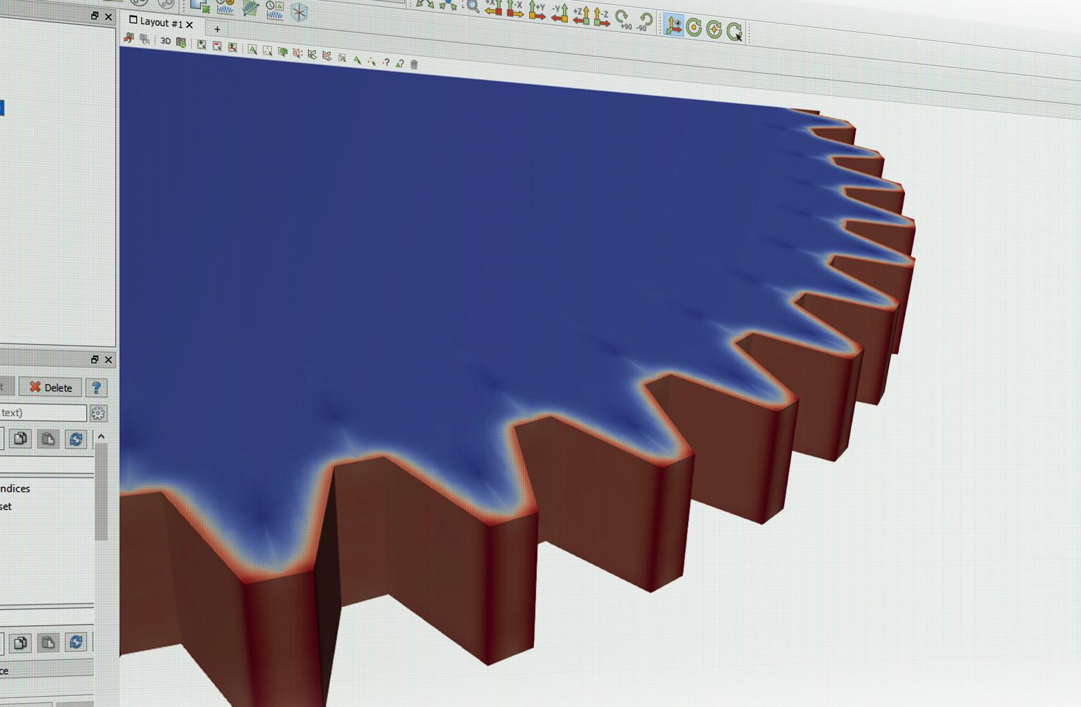
  • The physics involved in utilizing electromagnetic induction as a deliberate and controlled source of heat generation is extensive and multi-faceted. Computer simulation provides a quantitative approach to designing and developing induction heating processes, allowing complex physical phenomena that cannot be physically observed and/or measured to be clearly visualized and quantified.
  • Because electromagnetic induction offers an extremely effective, economical, and versatile means of heating conductive materials, the scope of induction heating applications is very broad. This includes (but is not limited to):
    • Heat treatment (hardening, tempering, normalizing, stress relieving)
    • Forming (hot/warm forging, rolling, stamping)
    • Joining (welding, brazing, soldering, bonding, shrink fitting)
    • Other (curing, coating, crystal growing)

Furthermore, each of these general applications includes countless different workpiece types, geometries, materials, and heating requirements. As a result, no “universal solution” exists in the design of induction heating equipment. Induction heating computer simulation offers the most efficient means of developing customized and optimized solutions and is, therefore, a necessity—not a luxury—in the modern induction heating industry.


Combining Simulation With Real World Tests for the Best Results

Example of simulation results (Photo: CENOS)

Inductor design is one of the most important aspects of the overall induction heating system. A well-designed inductor provides the proper heating pattern for your part and maximizes the efficiency of the power supply, while still allowing easy insertion and removal of the part. With the right design, it's possible to heat conductive materials of any size and form, or only the portion of material required.

Computer Simulation vs Experimental Method

Computer Simulation

Advantages

  • Can work for any geometry and operating conditions
  • Demonstrates the entire dynamics of the process
  • Leaves records for future
  • Limitless accuracy of calculations
  • Does not require special equipment
  • Less expensive and less time-consuming
  • Future improvements expected
  • Provides 3D process visualization for customers (pictures, video)

Limits and Disadvantages

  • Requires special software and databases
  • Not all the processes may be simulated (as of today)
  • Does not provide physical samples

Experimental Method

Advantages

  • May provide the most reliable results
  • Can show the performance of the whole system including unexpected effects and troubles
  • Does not require a material property database
  • Provides physical samples for properties validation

Limits and Disadvantages

  • May require expensive equipment
  • Does not provide a good understanding of the process
  • Difficult to transfer knowledge (to scale a company)
  • Case dependent accuracy
  • Limited access to production equipment (expensive)
  • Time-consuming—may cause production delay due to multiple design iterations.

Challenges in coil design

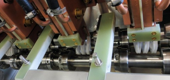
The induction coil, also known as an "inductor", is essential to induction heating. Single-turn, flexible, multi-turn cylindrical, left-turn, right-turn, rod-shaped, hair-pin, parallel, ear-shaped, tiny, big—whatever the coil shape and size—the right design maximizes the lifetime of the coil and ensures lowest energy consumption and best effects on work process and materials.

Many factors contribute to a coil’s effectiveness: the care taken to make it, the quality of the materials used, its shape, its maintenance, its correct matching with the power source, etc.

Here are just three of the many hurdles to be overcome in order to make safe and efficient coils:

Impedance matching

It is necessary to achieve the correct impedance matching between the coil and the power source in order to use the latter’s full power. The coil designer must also consider that coils need five to ten times as much reactive as active power.

Magnetic flux concentrators

Concentrators focus the current in the coil area facing the workpiece. Without concentrators, much of the magnetic flux may propagate around the coil. This flux could engulf adjacent conductive components. But when concentrated, the flux is restricted to precise areas of the workpiece.

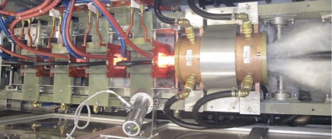
Water flow and speed

It is generally important to achieve an adequate flow of cooling water through the coil. When high power density is expected in the inductor, the coil designer must consider the flow rate and the water’s velocity. This is because velocity significantly influences the heat transfer between inductor and coolant and therefore has a major impact on the longevity of the coil. A booster pump is sometimes needed to maintain the desired flow and velocity. Professional designers will also specify a purity level for the water in order to minimize coil corrosion.

Tools and Processes Necessary To Ensure Coil Longevity and Performance

Advanced induction coil design includes:

  • Detailed analysis of specifications, available equipment, and environment
  • Coil style and heating process selection (scanning, single-shot, static, etc.)
  • 3D design programs and computer simulation for coil head optimization
  • Analysis of benefits of magnetic flux controllers application
  • Coil engineering (design of coil head, leads, structural components, quenchant supply, etc.)
  • Advanced manufacturing techniques, mandrels to achieve tight tolerances
  • Testing in a laboratory or industrial plant for performance and final dimensional check
  • Final corrections if required

Designing and making induction coils is technically challenging. Computer simulation helps tackle some of the challenges, limiting costs and maximizing effectiveness.

CENOS Platform's mission is to help companies switch from old and cumbersome experimental methods to a powerful computer simulation that is simple, affordable, and induction heating-focused. CENOS, combined with real-world trials, will yield the best results in a fast and cost-effective way.

How To Choose the Right Simulation Software

The induction heating market is small compared to other industrial sectors, and there are only a few specialized simulation packages on the market that can be used for induction process and coil design. Induction heating simulation involves a set of mutually coupled non-linear phenomena. Many induction applications are unique and may require different program modules. In addition to computer simulation software, an extensive material database is necessary for accurate results.

1D, 2D or 3D?

Majority of practical simulations now are being made in 1D or 2D approaches. But with 1D and 2D, the structure and geometry of real induction systems are often very simplified. In reality, a majority of induction systems are 3D. In addition, interference of induction device and source of power must be considered in many cases. That's why 3D will ensure less space for errors and a more thorough analysis.

Cloud vs Desktop

Working with cloud-based software requires uploading your data to the third party. Frequently induction heating equipment manufacturers are not allowed to share their customer CAD files with a third party due to NDA. Furthermore, while cloud computing may provide increased calculation speed, one should consider the time it takes for uploading the design files and downloading the result files.

Importance of training & support (time, costs)

There is a common opinion that simulation software requires a specially educated (and well paid) simulation engineer/analyst, usually hired only for one kind of task—simulation. This is definitely true for sophisticated multi-physics simulation packages, which might require 3 to 4 months of intense training because of a plethora of numerical aspects which should be taken into account in order to get reliable results in a simulation. However, CENOS 3D desktop software keeps focus solely on induction heating and tries to avoid any unnecessary functionality which might confuse an inexperienced user. By using CENOS-dedicated templates, a beginner can run his first induction simulation in just under 30 minutes and become a pro user with any 3D geometry after 2 weeks of training, guided by CENOS engineers.

Cost

Licensing software can cost $20,000 to $80,000 up front plus additional annual payments in 20% value of purchase price just for support and updates. And that's only for an induction heating module, whereas CENOS's annual license is $7,200 and requires no upfront investment. Alternatively, one could consider a “pay as you go” purchase model, paid by hours, but one must keep in mind that 3D calculations take time, which might make this particular subscription model cost inefficient.

Open Source software—a free alternative with some drawbacks

Open source is very cost efficient—open source tools like Elmer or GetDP are free to use. However, these tools might require a long training period (6 to 10 months); plus extra steps and routines required for everyday simulation will take up to 1,000 additional hours a year. Overall, open source tools are a solid choice because they are validated by the community but not focused on user experience.

Benefits:

  1. Community. Open source solutions often have thriving communities around them, bound by a common drive to support and improve a solution and introduce new concepts and capabilities faster, better, and more effectively than internal teams working on proprietary solutions.
  2. The power of the crowd. The collective power of a community of talented individuals working in concert delivers not only more ideas but quicker development and troubleshooting when issues arise.
  3. Transparency. Open source code means just that—you get full visibility into the code base, as well as all discussions about how the community develops features and addresses bugs.
  4. Reliability. Because there are more eyes on it, the reliability of open source code tends to be superior as well. Code is developed on online forums and guided by experts. The output tends to be extremely robust, tried, and tested. In fact, open source code now powers about 90% of the internet and is being rapidly adopted across major enterprises for this reason.
  5. Better security. As with reliability, open source software's code is often more secure because it is much more thoroughly reviewed and vetted by the community.

Drawbacks:

  1. Because there is no requirement to create a commercial product that will sell and generate money, open source software can tend to evolve more in line with developers’ wishes than the needs of the end user. For the same reason, they can be less “user-friendly” and not as easy to use because less attention is paid to developing the user interface.
  2. There may also be less support available for when things go wrong – open source software tends to rely on its community of users to respond to and fix problems.
  3. Because of the way it has been developed, open source software can require more technical know-how than commercial proprietary systems, so you may need to put twice as much time and effort into training employees to the level required to use it.
  4. Many different open source solutions are not compatible with each other. Take for example GetDP - an open source finite element solver, its core algorithm library uses its native pre-processing and post-processing tool Gmsh, which frankly, compared to other solutions, is not the best in its class.

CENOS Makes Open Source User-Friendly and Easy To Use

CENOS Platform uses GetDP solver and offers integration with far more superior open source tools like SALOME for pre-processing and Paraview for post-processing, which by default are not compatible with GetDP.

“CENOS” stands for “Connecting ENgineering Open Source”, highlighting its new software approach: connecting the best of open source tools in one seamless user experience. CENOS platform technology enables affordable simulation available for small to midsize companies by connecting third-party open source algorithms GetDP, Salome, and Paraview, developed by strong academic communities involving world top research centers and universities like Sandia National Lab, Imperial College, KU Leuven, and others. The academic world has already built plenty of smart algorithms; there is no need to charge money for the scientific heritage. Use of free open source algorithms makes it possible for CENOS to be affordable for everyone.

The company has built a user-friendly interaction layer and interconnection between previously incompatible separate open source software algorithms. CENOS Platform consists of a user interface, special data optimization procedures including necessary data reformatting for inter-operational compliance ensuring data flow and control between different open source tools. This way CENOS lets engineers save up to 80% of design time by replacing physical prototyping with powerful simulation software which is affordable and easy to use.

About the Authors: Dr. Mihails Scepanskis is the CEO and co-founder of CENOS LLC, based in Riga, Latvia. Dr. Vadims Geza is the chief scientist at CENOS.

Induction Heat Treatment & the Role of Simulation Software Read More »
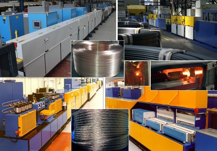
Dr. Valery Rudnev on … Equipment Selection for Induction Hardening: Continuous and Progressive Hardening, Part 3

This article continues the ongoing discussion on Equipment Selection for Induction Hardening by Dr. Valery Rudnev, FASM, IFHTSE Fellow. Dr. Rudnev previously reviewed equipment selection for scan hardening in three parts. The first part on equipment selection for continuous and progressive hardening is here; the second part is here. To see the earlier articles in the Induction Hardening series at Heat Treat Today as well as other news about Dr. Rudnev, click hereThis installment continues a discussion on equipment selection for continuous and progressive hardening applications.


Inductor Designs

So far, I have discussed the application of conventionally designed solenoid coils in continuous/progressive hardening applications. However, even multiturn solenoid-type coil geometries may have quite complex shapes accommodating the shape of induction hardened components. One illustration of this is shown in Figure 1 where two in-line multiturn solenoid-type inductors are used for heat treating of an irregular shape component.

Figure 1. Two in-line multiturn solenoid inductor of a complex shape. (Courtesy of Inductoheat Inc., an Inductotherm Group company)

Besides multiturn solenoid coils, channel-type multiturn inductors (also called slot or skid inductors) are frequently used in continuous/progressive heat treating. The channel inductor gets its name from its similarity to a long channel. This shape allows parts to be passed through the coil in a number of ways, such as a conveyor, shuttle, indexing, rotary or carousel table, turntable, or any other indexing system.

Channel coils permit easy entry and exit of the heated components to/from the inductor. Figure 2 shows images of some examples of multiturn channel inductors. The crossover ends of channel coils are bent away to allow the part to pass through. In some cases, the crossover ends are made high enough to ensure minimum impact on the heating of the part at the ends of the coil, minimizing electromagnetic forces when workpieces enter and exit the inductor. In other cases, the opposite might be true, and crossover coil regions play an important part in providing the needed temperature distribution.

Figure 2. Images of different examples of multiturn channel inductors. (Courtesy of Inductoheat Inc., an Inductotherm Group company.)

Channel coils are used to heat treat selected regions of parts, as well as entire components. These inductors are often used for through hardening, annealing, and tempering applications. However, if a specific case depth is required, rotation of the workpiece may be needed to even case depth.

Figure 3 shows a “state-of-the-art” continuous fed induction system for heat treating fasteners [2]. This system is adjustable for a wide range of fastener/bolt diameters and lengths (0.5–4.0 in. [12–102 mm]) and is capable of production rates of up to 600 fasteners per minute. The unique proprietary coil design developed by Radyne Corporation maximizes electrical efficiency and system flexibility while preventing stray heating of electrically conductive surroundings that may potentially cause undesirable heating of structures and malfunction of electronic devices. The rotary dial tooling is designed to accept bolt fasteners from the in-line vibratory feeder. The adjustable speed rotary table contains advanced safety features to prevent damage and meltdown.

The quench assembly allows adjusting the quench flow for the utmost in quench control. After spray quenching, parts are stripped from the traverse assembly and dunk quenched into the tank for final cooling to room temperature.

Figure 3 shows a “state-of-the-art” continuous fed induction system for heat treating fasteners [2].
The tooling is designed with a quick change feature to ensure that all tooling can be changed for a different part size in less than 15 minutes. The system is controlled through a controls package and HMI for part setup and part storage of different programs. Through this HMI, the power source coil “Z” adjustment can also be stored and adjusted for different bolt lengths assuring superior quality fasteners. This unit includes four sizes of tooling required for the rotary heat treat fixture and the traverse tooling: M6, M8, M10, and M12.

Besides solenoid coils and channel inductors, other inductor styles are used including split-return, hairpin and double hairpin inductors, transverse flux, and traveling wave inductors. However, an application of those inductors is not as frequent for continuous/progressive induction hardening.

References

  1. V.Rudnev, D.Loveless, R.Cook, Handbook of Induction Heating, 2nd Edition, CRC Press, 2017.
  2. J.Mortimer, V.Rudnev, Bernhard,A., Induction Heating and Heat Treating of Fasteners, Fastener International, February, 2019, p.50-53.

Dr. Valery Rudnev on … Equipment Selection for Induction Hardening: Continuous and Progressive Hardening, Part 3 Read More »

Dr. Valery Rudnev on . . . Equipment Selection for Induction Hardening: Continuous and Progressive Hardening, Part 2

This article continues the ongoing discussion on Equipment Selection for Induction Hardening by Dr. Valery Rudnev, FASM, IFHTSE Fellow. Dr. Rudnev previously reviewed equipment selection for scan hardening in three parts. The first part on equipment selection for continuous and progressive hardening is here; the third part is here. To see the earlier articles in the Induction Hardening series at Heat Treat Today as well as other news about Dr. Rudnev, click here


Frequency Selection

Depending on the application specifics, continuous and progressive hardening lines may use the same frequency for various in-line coils. In other cases, power levels and frequencies may be different at different heating positions. The presence of three general process stages (described in Part 1) makes a marked impact on a selection of process parameters and the design of an induction system.

When using different frequencies for the various heating stages, the coil design may need to change as well (e.g., a number of coil turns may need to be adjusted for load matching purpose). Just as the eddy current penetration depth in the heated part is affected by the frequency, the current flow in the inductor is affected as well. The wall thickness of the inductor turns (i.e., copper tubing wall) might need to be adjusted to accommodate different frequencies to maximize the coil electrical efficiency.¹

The wall thickness of an inductor’s heating face should be increased as frequency decreases. It is highly desirable for the current-carrying copper wall thickness to be 1.6 times greater than the current penetration depth in the copper (δCu). Increased kilowatt losses in the copper, which are associated with reduced electrical efficiency and greater water-cooling requirements, will occur if the wall is thinner than 1.6∙δCu. In some cases, the copper wall thickness can be noticeably thicker than the recommended value of 1.6∙δCu. This is because it may be mechanically impractical to use a tubing wall thickness of, for example, 0.25 mm (0.01 in.).

As an example, Figure 1 shows a number of continuous in-line multi-coil systems for induction heat treating wire products.²

Several continuous in-line systems for heat treating wire products (Courtesy of Radyne Corp., and Inductotherm Heating & Welding, UK. Both are Inductotherm Group companies.)

There are noticeable benefits of compact induction systems compared to fluidized beds, infrared heaters, and gas furnaces, such as quick response and the ability to provide a rapid change in the process operating parameters to accommodate the required temperature of the wire/cable being processed at speeds up to 5 mps. Frequencies that are in the range of 10 to 800 kHz are commonly applied. A dual-frequency concept can be beneficial to enhance electrical efficiency of while heating different diameters/thicknesses or it can be advantageous for through heating of metallic alloys that exhibit low toughness/high brittleness.

According to the dual-frequency concept, a lower frequency is used during the initial heating stage when the steel is magnetic. In the final heating stage, when the steel becomes nonmagnetic with significantly increased current penetration depth δsteel and becomes substantially more ductile, it is beneficial to use a higher frequency.

Case study¹:

As an example, consider the induction heating of a 1/8 inch-diameter (3.2 mm-diameter) steel rod from ambient to 2000°F (1100°C) using both a single 10-kHz frequency and dual 10-kHz/200-kHz frequencies (see Figure 2). When using the single frequency of 10 kHz (Figure 2, left), the rod’s final temperature experiences very little change regardless of the coil power that is increased more than fivefold (from 17 to 90 kW). The only noticeable difference is related to the initial slope of the temperature-time curve, where the steel is ferromagnetic. Upon reaching the Curie point, there is no noticeable temperature rise. This is the result of severe eddy current cancellation making the steel rod transparent (practically speaking) to the electromagnetic field of the induction coil.

Illustration of the dual-frequency concept when induction heating a 1/8 inch-diameter (3.2 mm-diameter) carbon steel rod from room temperature to 2012°F (1100°C) using both a single frequency of 10 kHz (a) and dual frequencies of 10 kHz/200 kHz (b). (Source: V.Rudnev, Systematic analysis of induction coil failures, Part 11c: Frequency selection, Heat Treating Progress, January/February, ASM Intl., 2008, pp. 27–29.)

In contrast, Figure 2, right, shows that a dual-frequency approach provides a remarkable improvement in the ability to heat the rod above the Curie temperature. A power of 14 kW/10 kHz was used to heat the rod below the Curie point and a power of 19 kW/200 kHz was used above it. The total required power is only 33 kW, compared with 90 kW using just 10 kHz, which was still unable to provide the required temperature rise.

Note: The target temperature of 2000°F (1100°C) is above typical target temperatures when hardening plain carbon or low alloy steels and it is more suitable for hot forming applications. This temperature was selected here to better illustrate a dual-frequency concept and the importance of avoiding eddy current cancellation when choosing operating electrical frequencies. It should be noted though that it is not unusual that the heat treating protocols/recipes for some alloyed steels and stainless steels may require target temperatures of 1900°F to 2100°F (1050°C to 1150°C) range.

In some not too often cases, three frequencies may be used. Lower frequency is applied for preheating inductors, a medium frequency is used for mid-heat inductors, and a high frequency is used for final heat inductors.

Sometimes, it is required that the induction system should be able to heat a variety of sizes using a single frequency. In these cases, in order to provide efficient steel heating, it is necessary to choose a frequency that will guarantee that the “diameter-to-current penetration depth (δsteel)” ratio exceeds 3.6 for any workpiece diameter or heating stage. Thus, it is important to remember that when calculating δsteel, the values of electrical resistivity and relative magnetic permeability of the heated material should correspond to their values at the highest temperature that occurs during the entire heating cycle.

The next installment of this column will review a variety of styles of inductors used in continuous and progressive induction hardening applications.


References

  1. V.Rudnev, D.Loveless, R.Cook, Handbook of Induction Heating, 2nd Edition, CRC Press, 2017.
  2. J.Mortimer, V.Rudnev, D.Clowes, B.Shaw, “Intricacies of Induction Heating of Wires, Rods, Ropes, and Cables”, Wire Forming, Winter, 2019, p.46-50

Dr. Valery Rudnev, FASM, IFHTSE Fellow, is the Director of Science & Technology, Inductoheat Inc., and a co-author of Handbook of Induction Heating (2nd ed.), along with Don Loveless and Raymond L. Cook. The Handbook of Induction Heating, 2nd ed., is published by CRC Press. For more information click here.

Dr. Valery Rudnev on . . . Equipment Selection for Induction Hardening: Continuous and Progressive Hardening, Part 2 Read More »

Dr. Valery Rudnev on . . . Equipment Selection for Induction Hardening: Continuous & Progressive Hardening, Part 1

This article continues the ongoing discussion on Equipment Selection for Induction Hardening by Dr. Valery Rudnev, FASM, IFHTSE Fellow. Previously, Dr. Rudnev reviewed equipment selection for scan hardening in three parts. This first installment in a new sub-series addresses equipment selection for continuous and progressive hardening. The second part in this series on equipment selection for continuous and progressive hardening is here; the third part is here. To see the earlier articles in the Induction Hardening series at Heat Treat Today as well as other news about Dr. Rudnev, click here


Introduction

The hardening of steels, cast irons, and P/M materials represent the most popular application of induction heat treatment. There are four primary methods for induction hardening [1]:

  • Scan hardening,
  • Continuous and progressive hardening,
  • Static hardening, and
  • Single-shot hardening.

These methods are related to the heating mode, essentials of inductor design, part geometry, and processing specifics. The previous three installments of this column, “Dr. Valery Rudnev on …”, discussed select subtleties associated with induction scan hardening. This article is devoted to continuous and progressive induction hardening techniques.

Continuous and Progressive Hardening

This method is commonly applied when heat treating elongated workpieces, such as bars, tubes, rods, wires, plates, beams, pins, and others. Long parts are more readily processed in a horizontal manner and heated as they progressively pass through multiple inductors. Inductors are positioned in-line or side by side. Each inductor may have a different design and power/frequency setting. This type of hardening is not limited to horizontally processed parts; vertical processing and arrangements at certain angles are also possible, if suitable.

There are also cases when a workpiece is statically heated to a certain temperature and then progressively moved to another heating position or static inductor for the next heating stage. These processes are referred to as progressive processing/heat treatment.

Induction practitioners sometimes consider continuous or progressive horizontal hardening systems as horizontal scanners. The difference is vague and it is a matter of terminology. Some heat treaters feel that it would be appropriate to differentiate these systems based on the number of inductors included in the induction machine design. Horizontal systems consisting of a single inductor are commonly referred to as horizontal scanners. In contrast, if a system consists of two or more heat treat inductors, then it might be referred to as a continuous or progressive heat treat system.

With the continuous hardening method, the workpiece is moved in continuous motion through a number of in-line inductors. Multiturn solenoid coils and, to lesser a degree, channel-style inductors and split-return inductors are most typically used in continuous heat treating lines. As an example, Figure 1 shows a side view of a horizontally arranged continuous induction system consisting of three in-line coils. Each coil consists of three turns.

Figure 1

As another example, Figure 2 shows a top view of a continuous heat treating line that comprises four in-line hardening coils and a spray quench device positioned after the last inductor. Workpieces (e.g., bars, shafts, rods, pins, etc.) are processed end-to-end through the inductors in a continuous motion.

Figure 2

Progressive multi-stage hardening is used when multiple workpieces are moved (via a pusher, indexing mechanism, robot, walking beam, etc.) through a number of coils. Therefore, the entire component or its portions are sequentially heated (in a progressive manner) at certain predetermined heating stages inside the in-line horizontal (being more typical) induction heater or a multi-position horizontal or vertical heater where coils are positioned side by side.

Continuous or progressive hardening methods are typically used for through hardening of elongated or moderate-length parts processing end to end and, to a lesser degree, for surface hardening. Outside diameters for case hardening (surface hardening) usually vary from 1/2 in. (12 mm) to 4 in. (100 mm). In through hardening applications of solid cylinders, the diameters may be as small as 1/8 in. (3 mm).

It is possible to recognize three heating stages in through hardening applications [1]:

  1. Initial or magnetic stage,
  2. Interim stage, and
  3. Final heating stage.

Initial or magnetic stage. Temperatures anywhere within the workpiece are below the A2 critical temperature (Curie point); thus, the steel is ferromagnetic and the current penetration depth is typically quite small. Skin effect is fairly pronounced at this stage and the heat source distribution resembles a conventional exponential distribution. The maximum power density is located at the surface and sharply decreases toward subsurface and the core. Heat source generation is localized by the fine surface layer of the workpiece. This leads to a rapid increase in temperature at the surface with a minor change in the core. This stage is characterized by high electrical efficiency often reaching 90% or so.

Interim stage. During this stage, the austenized surface layer and near-surface area is heated above the A2 critical temperature; however, the internal region, having temperatures below the Curie point, retains its ferromagnetic properties. At this stage, the power density distribution along the radius has a unique non-exponential “wave-like” distribution, which is very different from the commonly assumed exponential distribution. The cause for this behavior has been explained in Ref.1.

Final heating stage. The thickness of the austenized surface layer that exhibits nonmagnetic properties becomes greater than the current penetration depth in hot steel at a given frequency, and the “wavelike” distribution disappears. The classical exponential power density distribution will then take place. As expected, heat source generation depth has increased dramatically compared to an initial stage resulting in a more in-depth heating effect. With time, the core temperature exceeds the Curie point and the entire cross section will be nonmagnetic.

In surface hardening applications, there are typically only the first two heating stages.

Depending on the application specifics, the same frequency may be used for various coils or process stages. In other cases, power levels and frequencies may vary at the different heating stages. The presence of above-described process stages makes a marked impact on a selection of process parameters and design of an induction system and will be discussed in the next installment of this column.

References

1. V. Rudnev, D. Loveless, R. Cook, Handbook of Induction Heating, 2nd Edition, CRC Press, 2017.


Dr. Valery Rudnev, FASM, IFHTSE Fellow, is the Director of Science & Technology, Inductoheat Inc., and a co-author of Handbook of Induction Heating (2nd ed.), along with Don Loveless and Raymond L. Cook. The Handbook of Induction Heating, 2nd ed., is published by CRC Press. For more information click here.

Dr. Valery Rudnev on . . . Equipment Selection for Induction Hardening: Continuous & Progressive Hardening, Part 1 Read More »

Comparative Study of Carburizing vs. Induction Hardening of Gears

Modern rotary-wing aircraft propulsion systems rely on different types of gears to transmit power from the turbine engines to the rotors. The basic requirements of these gears are that they are high strength, sustain long life, meet weight considerations, and have a high working temperature and low noise and cost, among others.

Most importantly, these gears require a hard, wear-resistant surface with a ductile core.

Gas carburizing is the current heat treat method used to produce these aircraft quality gears, but this method of heat treatment is costly due to the large number of process steps, huge footprints, energy consumption, and environmental issues. Moreover, the final grinding of gear teeth to correct distortion produced during quenching reduces effective surface compressive stresses.

An investigation into low-cost alternatives for surface hardening aerospace spur gears was conducted where specimens of the selected gears were induction hardened using a patented process. Dimensional and microstructural analyses were conducted, and residual stress studies were performed. This article is a summary of the steps and observations of the case study that resulted from this investigation, which can be summarized this way:

The proposed induction process is a low-cost alternative to conventional gas carburization. In some applications, a 25% savings is estimated.

The first step to gear manufacturing demands a total understanding of aerospace gear requirements. As the gear transmits torque, the teeth are subjected to a combination of cyclic bending, contact stresses, and different degrees of sliding or contact behavior. It is, therefore, critical for a gear to have the proper case and core structure to withstand these loading conditions.

With every revolution, a cyclic bending load is applied, resulting in tensile stress at the root region of the gear. The core of the gear has to be soft to absorb impact load and prevent brittle failure. Due to high-speed contact between adjacent gear teeth, peak shear stresses generated at the surface act in the normal direction to the surface. Pitting, spalling, or case crushing types of failures can occur due to low residual stress or inadequate case depth.

For aircraft quality gears, typical surface hardness is around 58Rc to 60Rc. The case depth is in reference to 50Rc and is controlled by diametral pitch.

Carburization

Carburization hardening is the most widely used technique for surface hardening of aerospace quality gears. A brief introduction to carburization is necessary to understand the potential benefits of this process and how other surface transformation can improve on some of the drawbacks of this commonly used process.

After raw material is received, it is forged to achieve proper grain structure and core hardness. The alloy most commonly used is ASM 6260 (AISI 9310). This low carbon alloy steel exhibits high core toughness and ductility.

Parts are loaded in a furnace and heated to 1650ºF – 1750ºF in a carbon rich atmosphere, where approximately 1% carbon potential is maintained. The depth and level of carbon absorption depend on carbon potential, temperature, time inside the furnace, and the alloy content of the material. After the desired carbon gradient is achieved, the gears are cooled slowly. Then the parts are heated to austenitizing temperature and quenched.

The process depends on the size, geometry, dimension tolerances, and other gear requirements.

The heat treat cycles shown above are two commonly used carburization processes. The difference in post carburization steps depends on the alloy used and final product requirement.

The characteristic of carburization is the inherent distortion associated due to the difference in cooling rates between the thin web and thicker rim. Distortion can occur as a size growth, a change in involute profile, or the loss of crown in spur gears.

Case Hardening by Selective Heat Treatment

The number of process steps required to case carburize a gear can be significantly reduced only if the gear tooth surface areas are heat treated.

Processes for locally heating only the tooth surface include induction, flame, laser, and electron beam.

In order to use induction, steel with a minimum of 0.5% carbon must be used. Several different alloy steels were experimented with, such as AMS 6431, AlSl 6150, and AlSl 4350/4360/4370. These steels were selected due to their combination of toughness, temper resistance, hardenability, and strength. The hardened case is obtained by heating a specific volume of the tooth surface above the transformation temperature for that material. Rapid contour heating produced a case of martensitic structure around the profile-hardened area, resulting in high compressive residual stress at the surface at the root fillet. This compressive stress increases the tooth bending fatigue life, where tensile stress exists due to tooth bending.

Transformation hardening allows a significant reduction in process steps and associated fabrication costs, due to two different factors:

  1. Since sufficient carbon is already present in the base material, copper masking, plating, stripping and carburization steps are eliminated.
  2. In selective hardening, the area of the heated zone is limited to only the hardened sections, and distortion is minimal and predictable.

Surface hardening applications are generally controlled by three process parameters, namely frequency, power level, and time. In this respect, several different hardening processes have been used for gear hardening. The proposed method discussed in this presentation is known as Dual Pulse Induction Hardening (DPIH).

DPIH Process

The DPIH is a patented process (U.S. patent #4,639,279). The process uses single frequency for both the preheat and final heat cycles. Two different power levels are used. This allows the entire process to be performed in one setup, using a single solid-state power supply.

The DPIH process consists of the steps described below:


The heat treatment process steps for both the carburized and DPIH processes for the aircraft gear are compared below:


An 85% reduction in heat treat process steps occurs when the gear hardening method is changed from conventional gas carburization to DPIH.


Conclusion:

Comparison of the above data and the conventional carburization process to DPIH process.

Carburizing grade material has to be changed from low carbon to medium carbon steel for induction hardening. In both the processes, surface hardness achieved is comparable, but the characteristic of induction hardening is that the gear section maintains a constant hardness value from the surface up to the transition zone, where it rapidly drops to core hardness levels, unlike a more gradual decrease in hardness in case of carburized gears. Low distortion of induction hardening gear is also a major cost reducing factor.


Acknowledgment:

This work was performed at AGT, Division of General Motors.


Madhu Chatterjee is founder and president of AAT Metallurgical Services LLC in Michigan with extensive experience in advanced engineering, research and development, and process and product improvement. He is also one of the original dozen consultants that inaugurated Heat Treat Today’s Heat Treat Consultants resource page. You can learn more about Madhu Chatterjee here.


Look for more on aerospace heat treating in the upcoming special aerospace manufacturing edition of Heat Treat Today.

Comparative Study of Carburizing vs. Induction Hardening of Gears Read More »

Heat Treat Tips: Induction Heating — Stuff You Should Know

During the day-to-day operation of heat treat departments, many habits are formed and procedures followed that sometimes are done simply because that’s the way they’ve always been done. One of the great benefits of having a community of heat treaters is to challenge those habits and look at new ways of doing things. Heat Treat Today101 Heat Treat Tips, tips and tricks that come from some of the industry’s foremost experts, were initially published in the FNA 2018 Special Print Edition, as a way to make the benefits of that community available to as many people as possible. This special edition is available in a digital format here.

In today’s Technical Tuesday, we continue an intermittent series of posts drawn from the 101 tips. The category for this post is Induction Heating, and today’s tips–#29, #73, and #83–are from Dr. Valery Rudnev, FASM, Fellow of IFHTSE, “Professor Induction”, Director of Science & Technology at Inductoheat Inc., an Inductotherm Group company. Dr. Rudnev is a regular contributor to Heat Treat Today


Heat Treat Tip #29

Induction Heating Non-Ferrous Metals & Alloys

Dr. Valery Rudnev, FASM, Fellow IFHTSE, Professor Induction, Director Science & Technology, Inductoheat Inc., an Inductotherm Group company

Steel components by far represent the majority of hot worked and heat-treated parts for which electromagnetic induction is used as a source of heat generation. At the same time, many other non-ferrous metals and alloys are also inductively heated for a number of com­mercial applications. Induction heating of low electrically resistive metals such as Al, Mg, Cu, and others typically require using lower electrical frequencies compared to carbon steels, cast irons, or high resistive non-magnetic metals (such as Ti or W, for example) and metallic alloys. The lower value of electrical resistivity results in smaller current penetration depth (depth of heat source gen­eration), making it possible to apply much lower frequencies without facing the danger of eddy current cancellation.

Heat Treat Tip #73

Induction Hardening Powder Metal

When induction hardening powder metallurgy (P/M) materials, it is good practice to have a minimum density of at least 7.0 g/cm3 (0.25 lb/in.3). This will help obtain consistent induction hardening results. When hardening surfaces that have cuts, shoulders, teeth, holes, splines, slots, sharp corners, and other geometrical discontinuities and stress risers, it is preferable to have a minimum density of 7.2 g/cm3 (0.26 lb/in.3). Low-density P/M parts are prone to cracking due to a penetration of the gases into the subsurface areas of the part through the interconnected pores. Interconnected pores contribute to decreased part strength and rigidity compared with wrought materials. In addition, the poor thermal conductivity of porous P/M parts encourages the development of localized hot spots and excessive thermal gradients and also requires the use of quenchants with intensified cooling rates to obtain the required hardness and case depths. This is so because an increase in pore fraction and a reduction in density negatively affect the hardenability of P/M materials compared to their wrought equivalents.

Heat Treat Tip #83

Induction Hardening Cast Iron

Induction hardening of cast irons has many similarities with hardening of steels; at the same time, there are specific features that should be addressed. Unlike steels, different types of cast irons may have similar chemical composition but substantially different response to induction hardening. In steels, the carbon content is fixed by chemistry and, upon austenitization, cannot exceed this fixed value. In contrast, in cast irons, there is a “reserve” of carbon in the primary (eutectic) graphite particles. The presence of those graphite particles and the ability of carbon to diffuse into the matrix at temperatures of austenite phase can potentially cause the process variability, because it may produce a localized deviation in an amount of carbon dissolved in the austenitic matrix. This could affect the obtained hardness level and pattern upon quenching. Thus, among other factors, the success in induction hardening of cast irons and its repeatability is greatly affected by a potential variation of matrix carbon content in terms of prior microstructure. If, for some reason, cast iron does not respond to induction hardening in an expected way, then one of the first steps in determining the root cause for such behavior is to make sure that the cast iron has not only the proper chemical composition but matrix as well.


These tips were submitted by Dr. Valery Rudnev, FASM, Fellow IFHTSE, Professor Induction, Director Science & Technology, Inductoheat Inc, an Inductotherm Group company.


If you have any questions, feel free to contact the expert who submitted the Tip or contact Heat Treat Today directly. If you have a heat treat tip that you’d like to share, please send to the editor, and we’ll put it in the queue for our next Heat Treat Tips issue. 

Heat Treat Tips: Induction Heating — Stuff You Should Know Read More »

Skip to content