Readers are checking out Heat Treat Today’smagazine from March/April 2024. The annualAerospaceprint edition has a piece that sparked a comment from a reader. The letter from the publisher Doug Glenn entitled “Is It Time To Rethink the ‘Quality’ Movement?” discusses the current state of the quality movement.
Would you like to weigh in on the topic? Submit your question, comments, thoughts, or queries here or email Bethany Leone at editor@heattreattoday.com.
Here is an excerpt from the publisher’s page:
“One of the first thoughts I remember having about the corporate quality initiative I was involved with was the distinct lack of a definition of what ‘quality’ really meant. For many of the standards, they did not really care what you did (whether or not you did quality work), they just wanted you to prove you had documented your work, that your people knew said documentation existed, and they were following the processes you had described in documentation.”
This publisher’s page prompted this feedback from Jorg Demmel, founder, owner, and president of High Temperature Concept:
“There is one thing I’d like to ask you, because I just read your publisher letter. I like it, although the situation you describe is not ‘quality’ in my mind. It’s a great discussion, which is worth it!
“It’s, in my mind, an oversubscription of quality management and it’s industry. That’s something different than quality. I don’t like these guys called ‘auditors’. Some (or many) never learned what means ‘operational quality’.
“Did you know that e.g. an iso 9001 certified company doesn’t have to follow the iso 9001 10 chapters in their QM handbook. Or, that not all suppliers have to be rated. Or, that internal audits don’t have to be bureaucratic and elaborative. Etc.
“Conclusion: a QM system is only as good as it is based on the people on the shop floor, their motivation, experience and attitude, and the leadership commitment. I guess I missed something 😉.”
We welcome your inquiries to and feedback on Heat Treat Today articles. Submit your questions/comments to editor@heattreattoday.com.
What are the factors that lead to carburization and carbon transmission? How can heat treater avoid these unwanted reactions? Discover the challenges of CFC fixtures and the steps heat treaters can take to mitigate these challenges.
This Technical Tuesday article, written by Dr. Jorg Demmel, founder, 0wner, and president, High Temperature Concept, was first published in Heat Treat Today's March 2023 Aerospace Heat Treating print edition.
Introduction
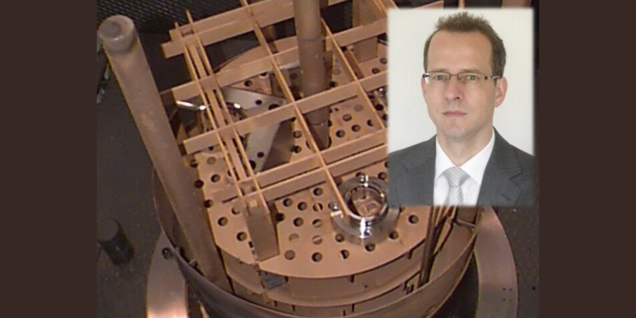
Dr. Jorg Demmel Founder, Owner, President High Temperature Concept
The main advantages of CFC fixtures were introduced in “CFC Fixture Advantages and Challenges in Vacuum Heat Treatment, Part 1,” which was released in Heat Treat Today’s November 2022 publication. This included a discussion of the limits of CFC in vacuum and protective atmosphere heat treatment. Successful applications of CFC workpiece carriers in heat treatment were presented along with field test results that included a brief discussion of undesired contact reactions (i.e., carburization and melting of parts). In Part 2 of this paper, the mechanisms involved with carburization and carbon transmission due to direct contact of parts with CFC fixtures will be further explained.
Mass Transfer from CFC Fixtures
Contact us with your Reader Feedback!
The mass transport of carbon from CFC fixtures into steel parts at high temperatures will be examined in the following areas:
Reactions in oxygen (i.e., the reaction medium)
Transport of carbon in CFC during exposure to oxygen
Transfer mechanism into the steel parts
Diffusion of carbon into the steel parts
Part reactions (melting, carbide formation)
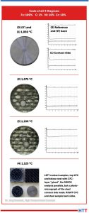
Figure 1: 1.6582 steel samples and GDEOS depth profile analysis Source: Dr. Jorg Demmel, High Temperature Concept
CFC samples were tested in contact with steel samples under laboratory conditions in a vacuum of 7.5 x 10⁻⁷ Torr (1 x 10⁻⁶mbar). Results of the contact with CFC for steel samples at different temperatures are presented to the left (Figure 1). It is important to note that:
Sample (0) is the reference sample and had no exposure to the contact test.
Sample (0’) is the back side of Sample (0).
Sample (1) is the contact side at 1922°F (1050°C).
All three samples are visually identical, therefore only one is shown. Sample (2) at 1967°F (1075°C) and Sample (3) at 2012°F (1100°C) exhibited a distinct visual surface pattern after CFC contact. This was analyzed by Glow Discharge Optical Emission Spectroscopy (GDOES) and the test location (gray spot) clearly observed on Samples (2) and (3). For Sample (4) run at 2057°F (1125°C), the CFC was found to have adhered to the steel surface.
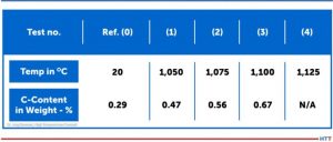
The carbon content in 10mm depth measured with GDOES (see the profiles in Figure 1) increased from initially 0.29 weight-% for the 1922°F (1050°C) test, although nothing was visible on metal surfaces. For carbon contents, see Table 1.
Table 1. Carburizing of 1.6582-samples in 10 µm depth after CX-27C1-contact (GDOES) Source: Dr. Jorg Demmel, High Temperature Concept
CFC Reactions with Oxygen
The chemical reactions of CFC with various gases are essential in Step 1 (referenced in Part 1 of this article) and an indicator of chemical thermal suitability.
In the case of the unwanted contact carburization considered above is similar, in a sense, to carburization of steel in contact with carbon powder or granulate. However, the actual carburization mechanism, which occurs between approximately 1616°F and 1697°F (880°C and 925°C), does not take place directly via the carbon contact but is based on the fact that solid carbon reacts with atmospheric oxygen according to the Equation Table to form carbon dioxide (CO2).
Equation Table. Reaction rates and activation energies for graphite (800°C; 0.1 bar) Source: Dr. Jorg Demmel, High Temperature Concept
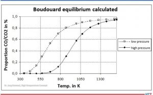
Carbon monoxide (CO) is then formed from CO2 by the Boudouard reaction (Equation 3). At high temperatures and low pressures (see Figure 2), almost only CO is present.
Figure 2. Boudouard equilibrium Source: Dr. Jorg Demmel, High Temperature Concept
Transport of Carbon
The carbon carrier must be transported to the surface of the parts.
The cases considered in Part 1 of this article were conducted in vacuum, that is in the absence of a carburizing atmosphere. The laboratory tests were even carried out in a vacuum as low as 7.5 x 10⁻⁷ Torr (1 x 10⁻⁶mbar). Nevertheless, part surface reactions were observed.
Transfer Mechanism into the Steel Parts
Theoretically, carbon from the CFC fixtures can be transferred into the steel via solid phase (as opposed to gaseous phase) reactions. Gas particles can be adsorbed by surfaces via physisorption and/or chemisorption. The author’s personal research experience has shown that metal samples usually oxidize after a short time, even in a high vacuum of 7.5 x 10⁻⁷ Torr (1 x 10⁻⁶mbar). In particular, elements such as iron, molybdenum, and chromium have a strong ability to chemically adsorb oxygen or CO.
Furthermore, there is a disproportionately large amount of adsorbed oxygen in the CFC samples. CFC has open porosities as high as 30%. CFC in industrial practice is never completely evacuated. So, there is a disproportionately large amount of oxygen present in CFC fixtures.
It can be assumed that oxygen repeatedly escapes from the CFC and is initially available in the contact area. Proof of this can be provided by the GDOES analysis. Outside the contact areas, no (gas) carburization took place (as evidenced by the non-contact side of steel samples).
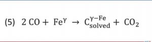
The oxygen and carbon surplus combined with close contact lead to complete reaction of oxygen creating carbon dioxide as in Equation (1). Because of the carbon surplus, almost only carbon monoxide is produced as shown in Equation (2). Because of the very close contact between CFC and steel, C-adsorption by gamma iron and desorption of carbon dioxide as in Equation (5) takes place:
Equation 5 Source: Dr. Jorg Demmel, High Temperature Concept
Since carbon dioxide immediately comes in contact with carbon in the CFC again, carbon monoxide is produced according to Equation (3). In other words, carbon dioxide regenerates immediately and the reaction starts again.
Direct carbon transfer from CFC to metal via solid phase is very unlikely since carbon atoms in CFC are firmly bound in rings.
Diffusion of Carbon in the Steel Parts
In solids, the surface diffusion usually takes place at significantly higher diffusion rates than in the bulk material. The thermodynamic driving force of diffusion or carburizing reactions is the difference in carbon activity for a specific concentration in the austenite to that of the reaction medium. The carbon activity is the ratio of the vapor pressure of the carbon in state under consideration to vapor pressure of pure carbon (graphite/CFC). Alloying elements of the steel influence the activity of the carbon.
Part Reactions (Melting and Carbide Formation)
Steel can begin to melt if, at the given values for temperature and pressure, a partially liquid phase is reached, that is, the solidus line in the phase diagram is exceeded. At even higher temperatures, the liquidus temperature can be reached and steel is completely liquid.
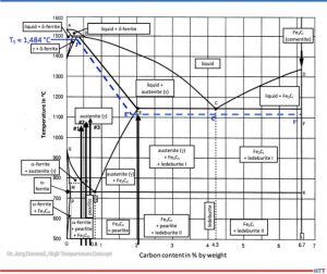
According to metastable iron-carbon diagram phase diagram (Figure 3), a steel such as SAE/ AISI 4340 (34CrNiMo6) alloy (DIN 1.6582) with around 0.47% by weight percent carbon does not begin to melt at 1922°F (1050°C), the exposure temperature for Sample (1), or Sample (2) at 0.56% and 1967°F (1050°C) for Sample (3) with 0.67% for 2012°F (1100°C). The iron-iron carbide phase diagram applies to steels with less than 5% (by mass) of alloying elements and thermodynamic equilibrium, so it is an accurate representation for a SAE/AISI 4340 (34CrNiMo6) alloy.
Figure 3. Metastable equilibrium diagram Fe-Fe3C for steel (good fit for 1.6582) Source: Dr. Jorg Demmel, High Temperature Concept
A calculation of the solidus temperature shown on the iron-iron carbide diagram (Figure 3), which is dependent on the carbon content and alloying elements, yields a value of 2703.2°F (1,484°C) (J’).
For an SAE/AISI 4340 (34CrNiMo6) steel (DIN 1.6582) with 0.3% C and one for 0.5% C, the calculated solidus temperature is 2640°F (1449°C). This is shown on the J’-E’ blue dotted line in Figure 3. In other words, a lower solidus line (cf. dashed blue line in Figure 3) and thus a slight reduction in austenite phase region.
The iron-carbon diagram also indicates that melting of surfaces that have absorbed carbon (e.g., Sample No. 2) will occur at 1967°F (1075°C). This value is within approximately 90°F (50°C) of the temperature used (dotted line E’-C’-F’). From this information we can conclude that the observations seen in Figure 1 are not the result of melting, but rather imprints due to surface softening.
The melting (c.f., Figure 1) observed in Test No. 4, which occurred at 2057°F (1125°C) is likely due to partial carburization of the steel surface and exceeding the solidus temperature. A micrograph confirms eutectic melting and high carbon content, which could also be indirectly confirmed by hardness measurement.
Carbide Formation
Additional reactions can occur between carbon absorbed from the CFC fixtures and the steel parts due to either separation of carbides (e.g., iron carbide in the form of secondary cementite) or carbide formation with alloying elements such as Ti, V, Mo, W, Cr, or Mn (listed in decreasing tendency to form carbides).
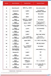
Table 2. Reactions between C and metal Source: Dr. Jorg Demmel, High Temperature Concept
Table 2 lists various elements in alphabetical order that react with carbon above the specified temperatures to form reaction products mentioned, primarily carbides. It should be noted that the temperatures listed apply only to pure metals and pure carbon. As such, they provide only rough approximations of a temperature at which a reaction might begin.
Countermeasures
There are several measures to avoid these unwanted reactions:
Ceramic oxide coatings such as aluminum oxide (Al2O3) or zirconium oxide (ZrO2) layers placed onto the CFC
Hybrid CFC fixtures having ceramics in key areas to avoid direct contact with metal workpieces
Alumina composite sheets
Boron nitride sprays
Special fixtures made of oxide ceramics
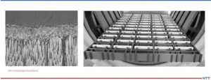
An yttrium-stabilized zirconium oxide layer (93/7) was applied to CF222 by thermal plasma spray and tested successfully (see Figure 4).
Figure 4. Yttrium-stabilized zirconium oxide layer with an average layer thickness of 110µm on CF222 material. The photograph on the right shows a hybrid CFC fixture. Source: GTD Technologie Deutschland
Summary
It is important to consider the specific process conditions in advance so that unwanted reactions — from carburization to catastrophic melting of the workpieces — can be avoided. Effective countermeasures can be taken.
References
Atkins, P. W.: Physikalische Chemie. 1. vollst. durechges. u. berichtigter Nachdr.d. 1. Aufl ., Weinheim, VCHVerlag, 1988 – ISBN 3-527-25913-9.
Bürgel, R.: Handbuch Hochtemperatur-Werksto technik: Grundlagen, Werksto bean-spruchungen, Hochtemperaturlegierungen. Braunschweig, Wiesbaden: Vieweg, 1998. ISBN 3-528-03107-7.
Demmel, J.: Advanced CFC-Fixture Applications, their scientific challenges and economic benefits, In: 30th Heat Treating Society Conference & Exposition, Detroit, MI, USA, 15th Oct. 2019.
Demmel, J.: Werkstoffwissenschaftliche Aspekte der Entwicklung neuartiger Werkstückträger für Hochtemperaturprozesse aus Faserverbundkeramik C/C und weiteren Hochtemperaturwerkstoffen, Dissertation, TU Freiberg, Germany, 2003.
Demmel, J.: Why CFC-Fixtures are a Must for Modern Heat Treaters, FNA 2020 Technical Session Processes & Quality, USA, 30th Sept. 2020.
Demmel, J., et al: Applications of CMC-racks for high temperature processes. In: 4th Int. Conf. on High-Temperature Ceramic Matrix Composites, 3.10.2001, p. A-17.
Demmel, J. und J. Esch: Handhabungs-Roboter sorgt für Wettbewerbsvorsprung. Härterei: Symbiose von neuen Werkstoffen und Automatisierung. In: Produktion (1996), No. 16, p. 9.
Demmel, J. und U. Nägele: CFC revolutioniert die Wärmebehandlung. In: 53. Härterei-Kolloquium, Wiesbaden, 10.10.97. Vortrag und Tagungsbericht.
Demmel, J., Lallinger, H.: CFC-Werkstückträger revolutionieren die Wärmebehandlung. In: Härtereitechnische Mitteilungen 54, No. 5, p. 289-294, 1999.
Eckstein, H.-J., et al: Technologie der Wärmebehandlung von Stahl. 2nd Edition, VEB Deutscher Verlag für Grundstoffindustrie, Leipzig, 1987. ISBN 3-342-00220-4.
Godziemba-Maliszewski, J.; Batfalsky, P.: Herstellung von Keramik-Metall-Verbindungen mit Diffusionsschweißverfahren. In: Technische Keramik, Jahrbuch, Essen, 1 (1988), S. 162-172. ISBN 3-80272141-1.
Grosch, J.: Grundlagen-Verfahren-Anwendungen-Eigenschaften einsatzgehärteter Gefüge und Bauteile, ExpertVerlag, 1994, ISBN 3-8169-0739-3.
Hollemann, A.F.; Wiberg, E.: Lehrbuch der anorganischen Chemie / Hollemann-Wiberg. 91.-100. Aufl ., de Druyter Verlag, 1985 – ISBN 3-11-007511-3.
Kriegesmann, J.: Technische Keramische Werkstoffe. Loseblattwerk mit 6 Ergänzungslieferungen pro Jahr.
Kussmaul, K.: Werkstoffkunde II. Stuttgart, Universität, Lehrstuhl für Materialprüfung, Werkstoffkunde und Festigkeitslehre, Vorlesungsmanuskript, 1993.
Lay, L.: Corrosion Resistance of Technical Ceramics. 1. Aufl ., Teddington, Middlesex, Crown-Verlag, 1983 – ISBN 0-11-480051-0.
Marsh, H.; u.a.: Introduction to Carbon Science. 1. Aufl ., London, Butterworths-Verlag, 1989 – ISBN 0-40803837-3.
Spur, G.: Wärmebehandeln. Berlin, 1987, ISBN 3-446-14954-6.
Samsonow, G.V.: Handbook of refractory compounds. New York, 1980.
Schulten, R.: Untersuchungen zum Kohlenstofftransportmit Carbidbildung in Nickelbasis-legierungen. RWTH Aachen, Fakultät für Maschinenbau, Diss., 1988 Deutsche Keramische Gesellschaft, 1990 following. ISBN 3-87156-091-X.
About the Author: Dr. Jorg Demmel is the founder, owner, and president of High Temperature Concept. He received his Engineering Doctorate in the field of CFC workpiece carriers for heat treatment and served in different leading positions for Volkswagen before moving to the U.S. In this article, Demmel draws on his dissertation, “Material scientific aspects of the development of new Fixtures for high temperature processes made of fiber-composite ceramics C/C and other high temperature materials” (Technical University Mining Academy Freiberg, Germany, 2002/3), and his personal experiences. For more information, contact Jorg at jorg.demmel@high-temperature-concept.com
Find heat treating products and services when you search on Heat Treat Buyers Guide.com
What happens when a lead engineer sticks his head in new advancements in materials from NASA? For the author of this article, it means the successful research and development of a new generation of workpiece carriers and fixtures made from “a high-tech ceramic matrix composite of very strong carbon fiber,” that is, CFC.
This Technical Tuesday article, written by Dr. Jorg Demmel, founder, 0wner, and President, High Temperature Concept, was first published in Heat Treat Today's November 2022 Vacuum print edition.
Introduction: From NASA to Industrial Heat Treatment
Dr. Jorg Demmel Founder, Owner, President High Temperature Concept
In the mid-1990s, a development in materials from NASA moved into my focus. I was an associate and lead engineer at the Fraunhofer Institute in Stuttgart, Germany, so I posed the question: Could CFC material (carbon fiber-reinforced carbon) substitute for non-abrasion-resistant and brittle graphite as the material used for workpiece carriers in the soldering process of drills? The answer: yes. The story did not end here. This project, which included the automated handling of the drills in some continuous furnaces, was just the first accomplishment. What ensued was a successful research and development of a new generation of workpiece carriers and fixtures made from CFC (“Carbon Fiber Carbon”).
Material Properties and Main Advantages of CFC
Contact us with your Reader Feedback!
CFC (aka, CFRC, or C/C), which stands for carbon fiber-reinforced carbon, is a high-tech ceramic matrix composite of very strong carbon fibers (or fiber rovings) in a compensative carbon (graphite) matrix. Material properties of some relevant heat treatment fixture materials were evaluated, and some are shown in Figure 1. These CFC properties have the following positive effects when used as CFC fixtures for heat treatment:
Figure 1. Left to right for 2D CFC SGL Sigrabond Performance, heat resistant austenitic cast alloy steel ASTM A297-HK (ISO G-X 40 CrNiSi 25-20; 1.4848), wrought and annealed Ni alloy Inconel 601 UNS N06601 (NiCr23Fe15Al; 2.4851) and mechanically alloyed Fe alloy, oxide dispersion strengthened Plansee PM ODS 2000 (Cr Al 21 6; 1.4768).
Because of their low density, CFC fixtures have a lower weight than their steel alloy counterparts (about five times), which reduces the efforts for manual handling.
Because of the increased strength of CFC at high temperature, the fixture weight can be reduced further. Additionally, fixture volume can be reduced — in some applications dramatically — so that, when combined with a specific CFC fixture design, furnace capacities can be increased up to 100%.
The following characteristics of CFC fixtures are responsible for the longer fixture life cycles (up to greater than five times), less workpiece distortion and rework, and make an automatic workpiece handling possible for the first time ever: the low CTE (coeffcient of thermal expansion) value for CFC in the direction of the fiber, the fact that CFC is chemically inert in vacuum or
certain protective atmospheres, has an excellent thermal shock resistance, and it doesn’t grow, creep, or age like metals.
Although the specific heat of CFC is higher, the energy consumption can be reduced and shorter heating up and cooling down times can be reached, resulting in up to 30% shorter process cycle times for the same workpieces.
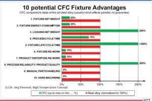
Figure 2. CFC fixture advantages in heat treatment
Figure 2 shows all potential advantages of CFC fixtures compared to state-of the- art steel alloy; a short payback time of the investment with high profitability are possible.
CFC Fixture Suitability in Vacuum Heat Treatment
Since CFC is made of carbon, it is not made for high temperatures above 752°F (400°C) in air or atmosphere with high percentages of oxygen, water vapor, hydrogen, or carbon dioxide for long periods of time. Therefore, vacuum or protective gas atmospheres are, in general, a suitable environment for CFC fixtures.
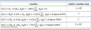
Table 1. Reaction rates and activation energies for graphite (800 °C; 0.1 bar). Equation (1) is the main combustion reaction, which has the strongest effect and is strongly exothermic (negative change of reaction enthalpies Δ"H). Reaction (2) is the so-called water gas reaction which shows the endothermic oxidation of carbon with vapor. Equation (3) is the Boudouard reaction which occurs endothermic above 700 °C. According to the Boudouard equilibrium the C0/CO2 ratio increases with increasing temperatures and decreasing pressures. Reaction (4) is the methane formation reaction: hydrogen reacts with carbon at temperatures above about 700 °C to CH4. Below 546 °C methane decomposes in carbon and hydrogen.
Table 1 shows the relative reaction rates for graphite according to H. Marsh in Introduction to Carbon Science, 1989 in the “reaction controlled” Zone I up to 1472°F (800°C) under oxygen, steam (H2O) Figure 3. Burning rates of graphite as a function of temperature
Industrial experience shows that CFC under vacuum of < 10-2 mbar at 1472°F or 1832°F (800°C or 1000°C) at a low dew point < -4°F (-20°C) (< 0.1 % vapor content) lasts at least 5,000 hours (real process time). At 3632°F (2000°C), the life is about 2,000 hours. Dew points of about 0°C (about 0.6 % vapor) cause higher reaction rates and reduce lifetime to about 800 to 1,000 hours.
Unwanted Contact Reactions
Contact reactions between the CFC fixtures and the workpieces, primarily made of steel, can lead to changes in the workpieces: for example, carburization of the workpiece in contact with the CFC. It is important to avoid these contact reactions since the properties of the workpieces must under no circumstances be changed in an uncontrolled manner. Neither the chemical composition nor mechanical properties nor the surface may change beyond the permissible tolerance limits. The CFC fixture should also not be subject to any changes that could adversely affect its properties and, above all, its service life.
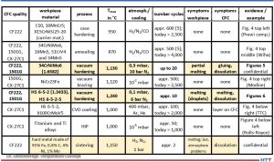
The following materials, consisting of mainly workpiece materials made of steel, were used in direct contact with CFC, especially in heat treatment and brazing. CFC 1501G (SGL), CF222 (Schunk), or CX-27C1 (GTD, Toyo Tanso) were used as CFC workpiece carrier materials. Table 2 gives an overview of the results. The symptoms columns with “none” indicate no problems. The colored cells showed problems. The last column references the application or the results.
Table 2. Contact/carburization test results from field trial, updated 2022
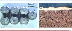
The contact partners and processes in which unwanted contact reactions occurred in the field test (colored in Table 2) and which are not confidential (bold font) are examined more closely in Part 2. See Figure 5 which shows some contact reactions on tempered steel drills after vacuum hardening at 2066°F (1130°C) under vacuum of 0.3 mbar (0.3 hPa or 225 mm Hg or “micron”).
Figure 5. Contact reactions on drill blanks (1.6582) with SiC-coated CFC (Schunk CF222P75 and SGL 1601YI); Scale left about 2:1 and right microsection about 400:1
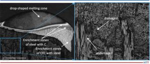
Figure 6 shows some heavy melting reactions of high-speed steel after vacuum hardening at 2264°F (1240°C) under vacuum of 0.1 mbar (0.1 hPa or 75 mm Hg or “micron”).
Figure 6. 1.3343 after contact with CFC CF222 at 2282°F (1250 °C) (left approx. 25:1; right detail 100:1)
The carbon transmission mechanism with unwanted carburization, along with eutectic reaction of some workpieces made of steel with CFC, and some technical solutions will be explained in Part 2 of this article.
References
Atkins, P. W.: Physikalische Chemie. 1. vollst. durechges. u. berichtigter Nachdr.d. 1. Aufl., Weinheim, VCHVerlag, 1988 – ISBN 3-527-25913-9.
Bürgel, R.: Handbuch Hochtemperatur-Werkstofftechnik: Grundlagen, Werkstoffbean-spruchungen, Hochtemperaturlegierungen. Braunschweig, Wiesbaden: Vieweg, 1998. ISBN 3-528-03107-7.
Demmel, J.: Advanced CFC-Fixture Applications, their scientific challenges and economic benefits, In: 30th Heat Treating Society Conference & Exposition, Detroit, MI, USA, 15th Oct. 2019.
Demmel, J.: Werkstoffwissenschaftliche Aspekte der Entwicklung neuartiger Werkstückträger für Hochtemperaturprozesse aus Faserverbundkeramik C/C und weiteren Hochtemperaturwerkstoffen, Dissertation, TU Freiberg, Germany, 2003.
Demmel, J.: Why CFC-Fixtures are a Must for Modern Heat Treaters, FNA 2020 Technical Session Processes & Quality, USA, 30th Sept. 2020.
Demmel, J., et al: Applications of CMC-racks for high temperature processes. In: 4th Int. Conf. on High-Temperature Ceramic Matrix Composites, 3.10.2001, p. A-17.
Demmel, J. und J. Esch: Handhabungs-Roboter sorgt für Wettbewerbsvorsprung. Härterei: Symbiose von neuen Werkstoffen und Automatisierung. In: Produktion (1996), No. 16, p. 9.
Demmel, J. und U. Nägele: CFC revolutioniert die Wärmebehandlung. In: 53. Härterei-Kolloquium, Wiesbaden, 10.10.97. Vortrag und Tagungsbericht.
Demmel, J., Lallinger, H.: CFC-Werkstückträger revolutionieren die Wärmebehandlung. In: Härtereitechnische Mitteilungen 54, No. 5, p. 289-294, 1999.
Eckstein, H.-J., et al: Technologie der Wärmebehandlung von Stahl. 2nd Edition, VEB Deutscher Verlag für Grundstoffindustrie, Leipzig, 1987. ISBN 3-342-00220-4.
Godziemba-Maliszewski, J.; Batfalsky, P.: Herstellung von Keramik-Metall-Verbindungen mit Diffusionsschweißverfahren. In: Technische Keramik, Jahrbuch, Essen, 1 (1988), S. 162-172. ISBN 3-80272141-1.
Grosch, J.: Grundlagen-Verfahren-Anwendungen-Eigenschaften einsatzgehärteter Gefüge und Bauteile, ExpertVerlag, 1994, ISBN 3-8169-0739-3.
Hollemann, A.F.; Wiberg, E.: Lehrbuch der anorganischen Chemie / Hollemann-Wiberg. 91.-100. Aufl ., de Druyter Verlag, 1985 – ISBN 3-11-007511-3.
Kriegesmann, J.: Technische Keramische Werkstoffe. Loseblattwerk mit 6 Ergänzungslieferungen pro Jahr.
Kussmaul, K.: Werkstoffkunde II. Stuttgart, Universität, Lehrstuhl für Materialprüfung, Werkstoffkunde und Festigkeitslehre, Vorlesungsmanuskript, 1993.
Lay, L.: Corrosion Resistance of Technical Ceramics. 1. Aufl ., Teddington, Middlesex, Crown-Verlag, 1983 – ISBN 0-11-480051-0.
Marsh, H.; u.a.: Introduction to Carbon Science. 1. Aufl ., London, Butterworths-Verlag, 1989 – ISBN 0-40803837-3.
Spur, G.: Wärmebehandeln. Berlin, 1987, ISBN 3-446-14954-6.
Samsonow, G.V.: Handbook of refractory compounds. New York, 1980.
Schulten, R.: Untersuchungen zum Kohlenstofftransportmit Carbidbildung in Nickelbasis-legierungen. RWTH Aachen, Fakultät für Maschinenbau, Diss., 1988 Deutsche Keramische Gesellschaft, 1990 following. ISBN 3-87156-091-X.
About the Author: Dr. Jorg Demmel is the founder, owner, and president of High Temperature Concept. He received his Engineering Doctorate in the field of CFC workpiece carriers for heat treatment and served in different leading positions for Volkswagen before moving to the U.S. In this article, Demmel draws on his dissertation, “Material scientific aspects of the development of new Fixtures for high temperature processes made of fiber-composite ceramics C/C and other high temperature materials” (Technical University Mining Academy Freiberg, Germany, 2002/3), and his personal experiences. For more information Contact Jorg at jorg.demmel@high-temperature-concept.com
Find heat treating products and services when you search on Heat Treat Buyers Guide.com