helios electrical corporation

Stop the Burn: 3 Tips to Cut Natural Gas Costs

op-edFor the next series of articles on heat treaters and combustion, the focus will be on the cost of natural gas and how we can reduce its consumption. Given significant movements in natural gas prices, it is essential we shift our focus to this important pocketbook issue.

This Technical Tuesday column appeared in Heat Treat Today’s November 2021 Vacuum Furnace print editionJohn Clarke is the technical director at  Helios Electric Corporation and is writing about combustion related topics throughout 2021 for Heat Treat Today.


John B. Clarke
Technical Director
Helios Electrical Corporation
Source: Helios Electrical Corporation

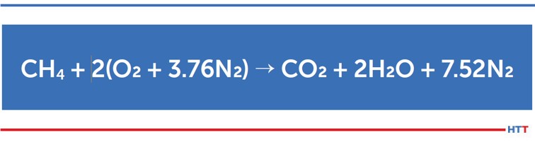
What Is the Cost To Operate My Burner System?

We will begin this and future articles by looking at natural gas prices and price forecast(s) that are published by the Department of Energy’s Energy Information Agency (EIA). Unlike the price for gasoline, we don’t drive past large, illuminated billboards displaying the current price of natural gas on our way to work, even though it is a significant operating cost for all heat treaters. Even if you operate primarily electrically heated equipment, natural gas is likely used to generate your electrical power. Obviously, neither Heat Treat Today or this author make any claims as to the accuracy of these projections. In other words, please don’t shoot the messenger. The American taxpayer funds this agency and it is only reasonable that we see what they have to say.

Let’s start with a quick definition. Henry Hub is a gas pipeline located in Erath, Louisiana that serves as the official delivery location for futures contracts on the New York Mercantile Exchange. This hub connects to four intrastate and nine interstate pipelines. It is unlikely any industrial consumer pays the Henry Hub price alone for the natural gas they consume. There are a great many other factors that determine the price that appears on your monthly bill; but the Henry Hub price is indicative of pricing trends and represents a consistent way to discuss the cost.

A good website to bookmark in your browser is www.eia.gov/naturalgas/weekly/. It is a quick read and will be the primary reference for my monthly sidebar. Let’s first look at the spot price trend. The spot price is the current price at which a natural gas can be bought or sold for immediate delivery at the Henry Hub. There is volatility in the price of natural gas because of supply, demand, and trading activities (speculation), but when we expand the time horizon, it provides a representative look at the pricing trend. This trend will be reflected in the price we will pay in the future. The prices quoted are in terms of U.S. Dollars per 1,000,000 BTU — roughly 1,000 SCF of natural gas.

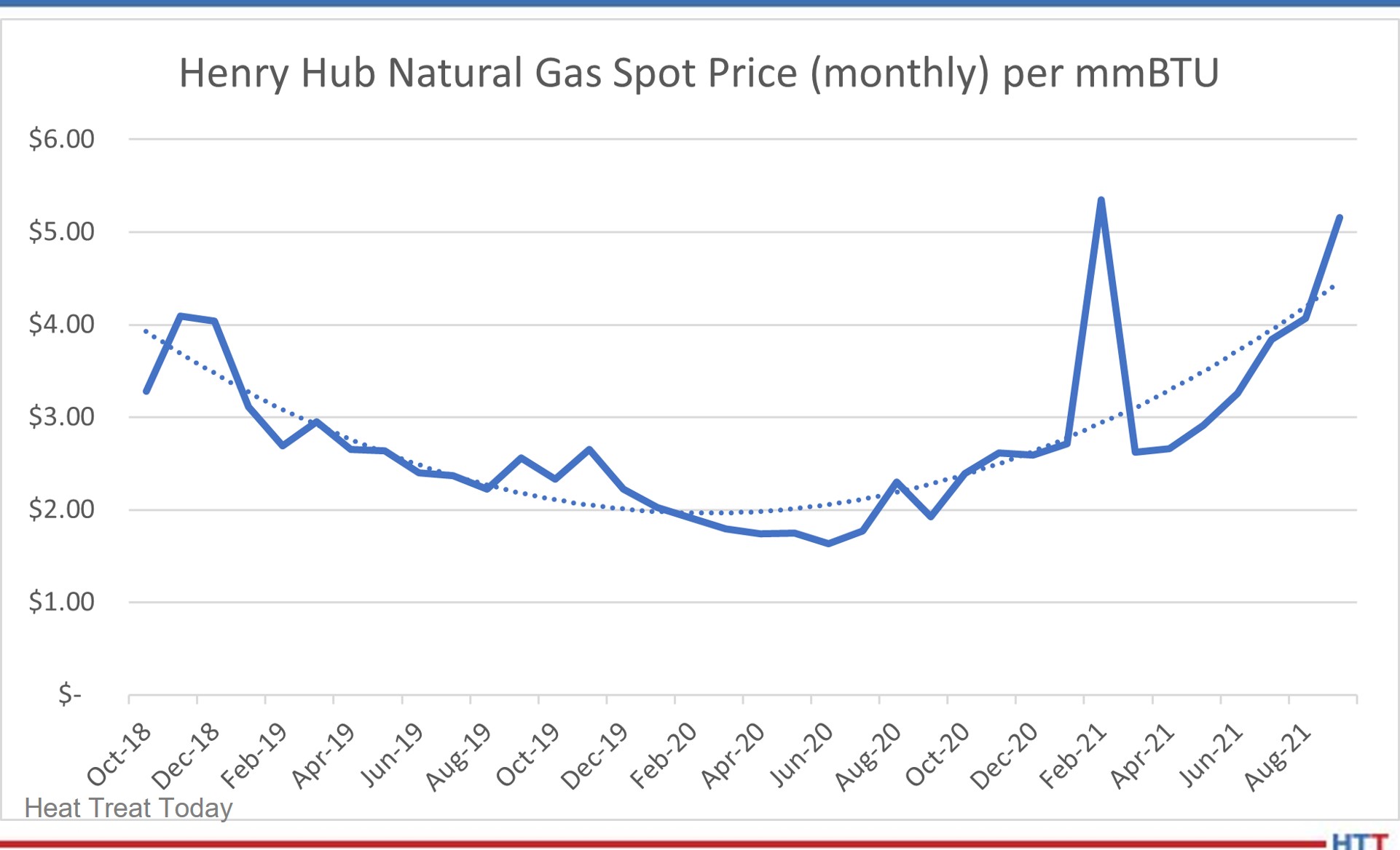
The EIA also provides forward-looking projections — but we will leave it to the reader to explore this information on the EIA website. The intent of this series of articles is not to provide the basis of trading futures, but rather to provide some ideas on how to save money.

We can see a definite upward trend. When we combine this data with our understanding that natural gas is increasingly being used to displace coal to generate electricity and North America’s increasing capacity to export liquified natural gas (LNG), there is reason to believe this is a durable trend. We can expect to pay more next year than the recent past to heat our equipment. And in time, this higher fuel cost will lead to higher electrical rates.

How Can I Save Natural Gas?

To save natural gas, we can optimize our processes, reduce unnecessary air, and contain heat within the furnace and/or capture the energy that leaves our system to preheat work or combustion air. Ideally, we should take advantage of all these opportunities — provided the effort pays for itself. In general, operators of heat processing equipment are aware of these opportunities but are not always confident when determining the payback for their investments in time and capital. We will endeavor to bring clarity to these decisions by not only discussing opportunities, but also discussing how to quantify the value of the opportunities. The following are the questions that will be answered in future articles:

Optimizing the Process:

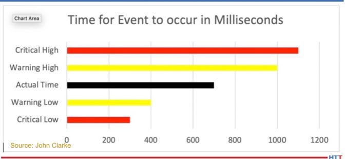
  1. How do I know when the material I am heating is at the desired temperature?
  2. Do I have excessive factors of safety built into my process to compensate for not knowing the temperature at the core of the part being heated?
  3. How much fuel can I save with a shorter cycle?

Reducing Air or Containing Heat:

  1. Is my furnace or oven at the correct internal pressure?
  2. Is it time to rebuild door jams?
  3. How much fuel is wasted because I am not containing heat within the furnace or letting excessive air reduce my combustion efficiency?

Reducing the Heat Exiting the System:

  1. Can I justify installing recuperators to preheat combustion air?
  2. Can the heat from my system be used to preheat work? If so, will I shorten my cycle time and save fuel?

No one likes rising energy prices, but if the trend is up, it is better to recognize reality and invest accordingly. It is our wish that future columns will provide ideas and tools to help you get the most from the energy you consume. If you have specific requests or questions that might guide our discussions, please let us know.

About the Author:

John Clarke, with over 30 years in the heat processing area, is currently the technical director of Helios Corporation. John’s work includes system efficiency analysis, burner design as well as burner management systems. John was a former president of the Industrial Heating Equipment Association and vice president at Maxon Corporation.

Stop the Burn: 3 Tips to Cut Natural Gas Costs Read More »

Moving Beyond Combustion Safety — Designing a Crystal Ball

In June, we spent a good deal of time discussing a simple pressure switch to emphasize the many considerations that are necessary for proper installation. Now we will expand the discussion to how the switch works and what steps we can take to detect a failure that is likely to occur sometime in the future.

This column appeared in Heat Treat Today’s 2021 Automotive August print edition. John Clarke is the technical director at  Helios Electric Corporation and is writing about combustion related topics throughout 2021 for Heat Treat Today.


John B. Clarke
Technical Director
Helios Electric Corporation
Source: Helios Electric Corporation

A pressure switch is a Boolean device — it is either on or off — so how can we evaluate its performance in a manner where a potential failure can be detected before it occurs? The simple answer is time — how long does it take for the switch to respond to the condition it is intended to sense? What is the period between starting an air blower and the pressure switch closing? Has this time changed? Is a change in this time period to be expected, or does it portend a future failure?

A simple approach to evaluating this pressure switch’s time is to create predetermined limits — if the switch responds either too rapidly or too slowly — an alarm is set and the operator is alerted. Graph 1 illustrates this approach.

In Graph 1, the black band represents the time between the action (the start of the air blower) and the pressure switch closing. There is a warning band (yellow) — both high and low — that provides the early warning of a system performance problem. There is also a critical band (red) — both high and low — that provides the point at which the feedback for the pressure switch is determined to be unreliable. If the switch is part of a safety critical interlock, the system should be forced to a safe condition (in the case of a combustion system, with the burner off and a post purge being executed) if required.

Graph 1

Graph 2 depicts when a switch closing time exceeds the warning level. It could be the result of a problem with the blower and/or the pressure switch, but the deviation is not sufficiently large as to undermine confidence in the switch’s ultimate function.

Programmatically, if the time exceeds the warning band, and an alarm is registered, the responsible maintenance person is notified. If that is in the warning band, it can be addressed as time allows.

Graph 2

The warning bands give us the crystal ball to potentially see a problem before it causes a shutdown. As it is continuously monitored by the programmable logic controller (PLC), it may provide an increased level of safety, but that is dependent on a number of factors that are beyond the scope of this article.

The switch can be not only too slow to respond: an unusually fast response is a reason to be concerned as well. It could be that the pressure switch setpoint has been set too low — so low that it no longer provides useful feedback. Graph 3 is an example with an unusually fast response.

If the time is less than the “Critical Low” preset value, the switch’s feedback is determined to be unreliable. In this case, the setpoint may have been changed during a maintenance interval or even worse — the switch may be jumpered (this assumes we have an interlock string wired in series). The critical values are NOT intended to provide forward looking estimates of required maintenance — they are simply an enhanced safety measure.

This scenario assumes that the response of a component is consistent. In our example of a pressure switch monitoring an air blower, we can assume the time the blower required to reach full speed, the time for a pressure rise time in the air piping, and the responsiveness of the switch is consistent. These time intervals may not be consistent. The air supplied to the blower could be sourced from outside the building (temperate climate), which could cause air density changes between a cool, dry day and a hot, moist day. In this instance, what can be done to detect a failure?

An approach where we see fluctuations in the timing even in instances where all the components are operating properly would be to run a moving average of the time based on the last n operations. Then we compare the moving average to the last time and confirm that any change falls within a specific range.

Step 1 would be to average the last n values for the time required for the switch to trip. Then compare this value (ta) to the last time and see if the deviation exceeds the preset values. Let us assume if the time varies by more than 20% a warning should be issued to the maintenance staff.

Now this method will accommodate rapid fluctuations – but if the performance of the component degrades in a near linear fashion, this formula will not detect a premature failure.

An alternate approach would be to execute this routine on the first n cycles, as opposed to continuously updating the average. Using this method, the performance of the specific component is captured. Or this averaging can be executed on demand or based on the calendar or Hobbs timer.

These concepts are far from new, and it has only been because of the recent expansion in PLC memory storage capacity and processing power that it has been reasonable to perform this analysis on dozens of components on a furnace or oven. Remember, it is a shame to waste PLC processing time and memory!

One or more of these approaches, or similar approaches analyzing time, can indeed be a crystal ball that gives us warning of any of a number of potential failures — warning before a system shutdown is required.

About the Author:

John Clarke, with over 30 years in the heat processing area, is currently the technical director of Helios Electric Corporation. John’s work includes system efficiency analysis, burner design as well as burner management systems. John was a former president of the Industrial Heating Equipment Association and vice president at Maxon Corporation.

technical Tuesday

Moving Beyond Combustion Safety — Designing a Crystal Ball Read More »

Moving Beyond Combustion Safety — Plan the Fix

Last month we began the discussion about the relationship between combustion safety and uptime, highlighting how combustion safety, reliability, emissions, and efficiency are inseparable. This month, we will explore the subject in greater detail and outline a path that can both reduce the risk of an incident and protect the bottom line.

This article written by John Clarke, technical director at Helios Electric Corporation, appears in the annual Heat Treat Today 2021 Buyer's Guide June print edition. Return to our digital editions archive on Monday June 21, 2021 to access the entire print edition online!


John B. Clarke
Technical Director
Helios Electrical Corporation
Source: Helios Electrical Corporation

How many times have we heard the tale about the man with the leaky roof? He cannot fix his roof when it is raining, and the roof doesn’t need repaired when it is not. This story is also applicable to heating system maintenance, perhaps more so than other plant maintenance activities because it so seldom “rains.” Ovens and boilers tend to be very reliable. (This statement is true for equipment operating at low or moderate temperatures, less so for equipment operating above 1832°F (1000°C).) It is exactly when the machine is properly producing parts that the planning for combustion safety, availability, and performance must occur.

The first critical step we must take is to understand that combustion safety, routine maintenance, tuning, and calibration are parts of a larger work strategy. To focus solely on the annual inspection of safety components while ignoring system tuning will not only compromise tuning and efficiency, but also the safety. We have seen how managerial reactions to high profile incidents have caused some firms to dispatch teams to annually examine valves and pressure switches. This effort is highly compromised if it does not include all aspects of system maintenance as well as capturing what is learned each time to improve future inspections and equipment designs. There is data beyond pass and fail that is valuable if we wish to optimize the performance of our equipment

Let us assume it is a clear sunny day, and we are ready to invest some time in preparing to improve our combustion system starting with a deep dive examination of two pressure switches: the low fuel gas pressure switch (LFGPS) and high fuel gas pressure switch (HFGPS). These ubiquitous components are present on nearly every fuel train and are vital for safe operation. As their names imply, they monitor the fuel pressure and shut the safety valves if the fuel gas pressure is either too high or too low.

These switches must be listed for the service they provide by an agency independent of the manufacturer – UL, TUV, FM, etc. Simply looking for a stamp may not be enough; take the time to read the file or standard being applied by the agency and determine if it describes the application. Next, ask if the pressure switch carries the basic ratings expected, like the enclosure rating (Nema or IP). Is a Nema 1 switch operating in a Nema 12 area? Temperature ratings must be confirmed. All too often a component rated for 32°F (0°C) is applied in an outdoor environment in cold climates, or one with a maximum rating of 120°F (50°C) is applied next to the hot wall of a furnace. The component may operate out of specified environmental ranges for some time, but to apply a component in this manner is betting against the house – sooner are later we are going to lose. Ask the people of Texas if the bet against sustained cold temperatures in early 2021 was worth it.

"John Clarke, Technical Director, Helios Electrical The first critical step we must take is to understand that combustion safety, routine maintenance, tuning, and calibration are parts of a larger work strategy"

Next, let us look at the contact(s) rating of the switch and how it is applied to the burner management circuit. More often than not, these switches are in control circuits fused for more current than the contact rating. If the switch rating is too low, the electrical designer has an option to use an interposing relay to increase the current carrying capacity to this device. This relay is an added component, and as such, adds yet another possible point of failure. If the relay is interposed, is it dedicated to this one switch? Multiple devices being interposed by a single relay is prohibited by NFPA 86, for good reason. Is the relay designed to fail safely? That is, will a relay coil burn out or wiring fault close the critical safety valves? Is the wire gauge suitable for the current carried and protection device used?

Next, is the switch mounted in a safe location free from possible vibration or the foot of an eager  furnace operator? If the switch must be changed, are clearances provided to perform this maintenance? What is the mean time to replace (MTTR) the component? Is the way the device is wired providing a path for combustible gas to enter the control enclosure and cause an explosion? Flexible conduit, without a means to seal the connection, is a very common error. Use a properly specified cord and consider using some type of connector to terminate the wiring at the switch. A simple 7/8-16 or DIN connector not only provides additional protection from combustion gas getting into the electrical conduit but is also a great benefit when changing the component in a rush and helps to isolate the component’s control circuit during testing and calibration.

Is the pressure switch suitably protected from bad “actors” in the fuel gas? Perhaps soot is present that could foul narrow passages or H2S that could result in corrosion. These are rare conditions, but coke oven gas may not be as clean as purchased natural gas. Do we need to specify stainless steel components? Would a filter make sense to protect the switch and increase the intervals between maintenance?

Finally, let’s discuss pressure ratings. Unfortunately, nomenclature varies by manufacturer. What is the maximum pressure the device can sustain and not fail, i.e., leak fuel gas into the environment? Many switches can experience a pressure surge without risk of leakage, but the high-pressure event will damage the switch internally. It is important when determining if this rating is adequate to consider possible failure modes that might expose the pressure switch to excessive pressure. As a rule of thumb, a pressure switch must be able to sustain a surge pressure delivered to the inlet of the pressure reducing regulator immediately upstream of the device. Think of it this way, if the upstream regulator experiences a failure, the full pressure delivered to this regulator will pass to the pressure switch in question.

Other obvious pressure ratings are the maximum and minimum set points. The pressure switch should be set to trip as close to the middle of the range as possible and should never be set close to either the minimum or maximum setpoint. Is the pressure switch manually or automatically reset after a trip? In general, it is best practice that the LFGPS resets automatically, and the HFGPS requires a reset by the operator. This recommendation is because LFGPS trips each time pressure is removed from the system, and it is generally understood that the system needs fuel to operate. On the other hand, a high-pressure event is exceedingly rare, and the operator should be made aware of this unusual event.

This article has discussed a lot about the simple pressure switch. It appears to be a heavy lift to perform this analysis on every pressure switch in a facility, but take comfort, once the exercise has been completed on the first system, it is much easier to replicate what has been learned to properly assess other systems. We should most definitely insist that our OEM provides this data, in detail, when new equipment is supplied. Why did we review all these specifications? Because I have been around for a while and have seen nearly every one of these errors in the application of pressure switches on operating combustion equipment.

Next month, we will expand on the pressure switch discussion to describe the tune/calibration and testing processes. I hope this deep and specific dive has been of value. If you have any questions or comments, please let me know.

About the Author:

John Clarke, with over 30 years in the heat processing area, is currently the technical director of Helios Corporation. John’s work includes system efficiency analysis, burner design as well as burner management systems. John was a former president of the Industrial Heating Equipment Association and vice president at Maxon Corporation.

Moving Beyond Combustion Safety — Plan the Fix Read More »

Moving Beyond Combustion Safety

op-edIn this month’s column, John Clarke will expand his discussion beyond combustion safety to include the economic issues that are concerns to all equipment owners and operators.

This column appeared in Heat Treat Today’s 2021 Induction May print edition.

 John Clarke is the technical director at Helios Electric Corporation and is writing about combustion related topics throughout 2021 for Heat Treat Today.


John B. Clarke
Technical Director
Helios Electric Corporation
Source: Helios Electric Corporation

The furnace's or oven’s burner management system (BMS) and its associated components are all that stand between us and an incident. The severity of these incidents ranges from the very expensive — a damaged furnace or oven — to the tragic — loss of a human life. It is a testament to the good work of hundreds of people that combustion system explosions are so rare. That said, the risk to life and property mandates that we revisit this subject frequently, and the risk to profitability dictates we expand our consideration beyond safety to include uptime and quality, as well.

National Fire Protection Association Standard 86 (NFPA 86), or “Standard for Ovens and Furnaces,” provides a standard that is the most common guide to the application of combustion components used in the US. This excellent prescriptive standard reflects the common thinking of people with hundreds of years of combined experience; but it still requires expertise to properly interpret and apply its requirements. It is important to not only understand what component must be provided, but also why.

NFPA 86 is used as a guide for the design of your BMS which includes the various control components to properly monitor the startup and operation of the burner. NFPA 86 also applies to the fuel train, constructed of components that regulate the flow of fuel and air and includes blowers, regulators, valves, filters, and sensors. What BMS and fuel train safety system issues should most concern an end user? An end user must know what it really means when your system is stamped “NFPA 86 Compliant.” To paraphrase Clint Eastwood: The end user needs to know their system’s limitations.

The NFPA 86 standard has been developed to protect life and property, but not production and profits. It is also a prescriptive standard, providing specific guidance to what components need to be applied and in what order. The shortcoming of a prescriptive code is that it must be mostly generic, that is, it applies to types or classes of equipment as opposed to specific applications. Given the variety of burner applications used in industry, it would be impractical to specify every component, order, and wiring for every conceivable process heating application.

Why is this a concern for end users? A specific application may have unforeseen risks or are out of the scope of NFPA 86 . Critical failure modes may be indirectly associated with a burner failure. For example, loss of a process air flow may allow a heat exchanger to overheat before a high temperature limit instrument detects the temperature rise. In this case, the process air flow must be monitored, and the flow or pressure switch monitoring the air flow must be added to the interlock string. This way, the burner will shut off as soon as the air flow failure is detected and not wait for the heat exchanger’s temperature to rise to an unsafe temperature. Another reason to “exceed” the code is that often ovens or furnaces are one element in a much larger manufacturing system. An example would be a continuous paint line, where a failure of the curing oven might shut down an entire facility.

What should an end user do? Ensure the system provided meets the standards and codes, NFPA 86, the Fuel Gas Code (NFPA 54), NEC, etc. This level of compliance is the minimum – and is often not the optimal. Additionally, invite the OEM who built the system to apply their experience and exceed the standards if it provides a more robust system. It may cost a few dollars up front, but it will be pennies when compared to the cost of an incident or, in many cases, an outage.

Encourage your supplier to apply a recognized process to the system review, perhaps a failure mode effects analysis (FMEA) and factor in not only the cost of an incident, but the cost of lost production or quality rejects as well. Consider an independent third-party review – it never hurts to get a second opinion. Review the cost of redundancy, be it online or near online . What is the cost of a second flame rod and flame safeguard when compared to the value of four hours of production?

Next, review the steps to service the system. Look at the mean time to replace (MTTR) a failed component. Has the system been designed to be easily serviced? Are there pipe unions on either side of all critical valves? Where are the spare parts located? What skill trades are required to make the repair? Is post replacement calibration or testing required? And if so, has it been documented?

Ask if the BMS provides a clear indication of the reason for a shutdown. The interlock string, a logical series wiring of critical components where any one component indicating a fault will disable the combustion system, should be monitored in a way where the “first out” or component that will shut down the system, is clearly identified.

Lastly, it is the end user’s responsibility for periodic inspections and equipment maintenance. NFPA 86 prescribes that the BMS and fuel train components are inspected per the manufacturer’s recommendation, but at least once a year.

The annual inspection is a critical step for safe operation but is viewed by many end users as simply a cost. Add to this the relative reliability of most components and we are presented with the ironic risk that maintenance personnel may take short cuts during the periodic inspection. One such person may say, “I always check the low gas pressure switches and they always pass, so I thought, what would it hurt if I skipped the test this year?”

For a more robust inspection, consider adding more value to the process. Combine the safety inspection with an extensive equipment calibration and service: Replace the filters, change the thermocouples, calibrate the control instruments, tune the burner, check the fuel-to-air ratio of the burner, and inspect the BMS components. This adds value to the process and makes it more palatable for the maintenance department.

When the cost of downtime of a key piece of equipment is high, practice the repair, at least on paper. However, if a failed burner shuts down an automotive assembly line, isn’t it worth the time to run actual drills?

In general, most burner trips are the result of a failed sensor, a UV scanner, dirty flame rod, an open thermocouple, or the vibration from an unbalanced fan tripping a pressure switch. In other words, when this type of trip occurs, the greatest cost is lost production, followed by the labor to diagnose the problem and then the cost to replace the component. Generally, the purchase price of the component is far less than the other costs associated with the system trip. Do not be penny wise and pound foolish. Spare parts are a pretty good investment.

If you need the heat from a burner to make your product, it makes sense to not only consider safety, but also plan reduced downtime as well. In the coming articles, we will examine these issues in greater detail, so stay tuned.


References:
[1] https://www.nfpa.org/codes-and-standards/all-codes-and-standards/list-of-codes-and-standards/detail?code=86


About the Author:

John Clarke, with over 30 years in the heat processing area, is currently the technical director of Helios Corporation. John’s work includes system efficiency analysis, burner design as well as burner management systems. John was a former president of the Industrial Heating Equipment Association and vice president at Maxon Corporation.

Moving Beyond Combustion Safety Read More »

Excess Air: Its Role in Combustion and Heat Transfer

Excess air plays multiple roles in heat treating systems. Learn about its importance in combustion and heat transfer, and why being well-informed will help your system run at peak performance.

This original content article, written by John Clarke, technical director at Helios Electric Corporation, appeared in Heat Treat Today’s Aerospace March 2021 print magazine. See this issue and others here.


John B. Clarke
Technical Director
Helios Electric Corporation
Source: Helios Electric Corporation

Is your system running optimally? The following discussion will provide a better, albeit abbreviated, understanding of the role of air in combustion and heat transfer.

Excess air in heating systems plays many roles: it provides adequate oxygen to prevent the formation of CO or soot, can reduce formation of NOx, increases the mass flow in convective furnaces to improve temperature uniformity, and at times, wastes energy. Excess air is neither good nor bad, but it is frequently necessary.

To begin, we must first look at a basic formula. For our discussions, we will replace natural gas, which is a mix of hydrocarbons with methane (CH4). The oxygen (O2) is supplied by air.

The above simplified formula describes perfect or stoichiometric combustion. The inputs are methane and air (where only the O2 is used to oxidize the carbon and hydrogen in the methane), and the products of combustion (POC) consist of heated carbon dioxide (CO2), water vapor (H2O) and of course nitrogen (N2). (The actual reaction is far more complex and there are other elements present in air that we are ignoring for simplicity.) As we can see from the equation, the oxygen we need to burn the methane comes with a significant quantity of nitrogen.

In practice, it is very difficult to even approach this stoichiometric or perfect reaction because it would require perfect mixing, meaning that each molecule of methane is next to an oxygen molecule at just the right time. Without some excess air, we would expect some carbon monoxide and/or soot to be formed. Excess air is generally defined as the percent of total air supplied that is more than what is required for stoichiometric or perfect combustion. For natural gas, a good rule of thumb is to have about 10 cubic feet of air for every one cubic foot of fuel gas for perfect combustion. Higher air/fuel ratios, say 11:1, are another way of describing excess air.

In most heating applications, the creation of carbon monoxide and other unburnt hydrocarbons should be avoided, except in the rare cases where they serve to protect the material being processed. Employees must be protected from CO exposure; and soot can damage not only equipment, but the material being processed.

Source: Heat Treat Today

The amount of excess air that is required to find and combine with the methane is dependent not only on the burner, but also on the application and operating temperature as well. Some burners and systems can run with very little excess air (under 5%) and not form soot or CO. Others may require 15% or more to burn cleanly. Just because a burner performs well at 10% excess air in application A, does not necessarily mean the same level is adequate in application B.

Once the quantity of air exceeds what is needed to fully oxidize or burn the methane, combustion efficiency will fall because the added air contributes no useful O2 to the combustion process, and it must be heated. It is very much like someone putting a rock in your backpack before you set out for a 16-mile trek. Taking this analogy further, higher process temperatures equate to climbing a hill or mountain with that same rock — the higher the climb, or the higher the process temperature, the more energy you waste. Sometimes this added weight or mass can be useful.

The higher the excess air, the greater the mass flow. In other words, the total weight of the products of combustion goes up, and the temperature of the CO2, H2O, N2, and O2 goes down. If we are trying to transfer the heat convectively, this added mass or weight will provide improved heat transfer and temperature uniformity. A simple way to think of temperature uniformity is that the lower the temperature drop between the products of combustion and the material being heated, the better the temperature uniformity. Many heating systems are specifically designed to take advantage of this condition – higher levels of air at lower temperatures. This is especially true when convective heat transfer is the dominant means of moving heat from the POC to the material being heated (when the process temperature is roughly 1000°F or lower).

Source: Heat Treat Today

Some heating systems are specifically designed to operate as close to perfect combustion as is possible as the material is heated then switch to higher levels of excess air to increase the temperature uniformity as the setpoint temperature is approached. In other words, it provides efficient combustion when temperature uniformity is less of an issue and a very uniform environment as the material being processed nears its final setpoint temperature.

Of course, a system can be supplied with too much air, which can waste energy, but also prevent the system from ever reaching its setpoint temperature. The energy is insufficient to heat all the air, the material being processed, and compensate for furnace or oven loses. In these instances, it is obvious that we must reduce the air supplied to the system.

In indirect heating systems – where the products of combustion do not come in contact with the material being processed, like radiant tubes, for example — air in excess of what is required for clean combustion provides limited benefit and should generally be avoided. In these systems, it is best to play a game of limbo, “How Low Can You Go,” so to speak. Test each burner to see how much excess air is required to burn clean and add a little bit for safety. Remember, if you source your combustion air from outside in an area with significant seasonal variations, the blower efficiency will change, and seasonal combustion tuning is required.

Lastly, some burners require a minimum level of excess air to operate properly. This additional air prevents critical parts of the burner from overheating – or the air may limit the formation of oxides of nitrogen (NOx). In this application, altering the burner air/fuel ratio could generate excessive pollutants or even destroy the burner.

Efficiency is important, but the process is king. There is no magical air-to-fuel ratio and no single optimum level of excess air in the products of combustion. Each application is unique and must be thoughtfully analyzed before we can confidently say we have optimized our level of excess air. But careful attention paid to the effect that excess air has on your fuel-fired systems will pay dividends in improved safety and efficiency.

About the Author:

John Clarke, technical director at Helios Electric Corporation, a combustion consultancy, will be sharing his expertise as he navigates us through all things energy as it relates to heat treating equipment.

Excess Air: Its Role in Combustion and Heat Transfer Read More »