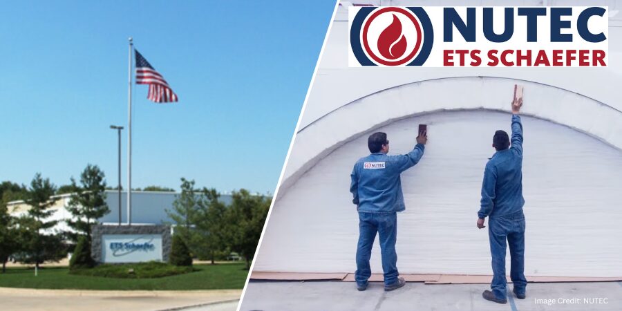
NUTEC Inc., a manufacturer of industrial insulation and fire protection products, has acquired ETS Schaefer LLC, a provider of monolithic ceramic fiber linings used in high-temperature applications. The acquisition, effective March 1, 2026, reflects ongoing activity in the thermal processing supply chain, where insulation systems play a key role in furnace efficiency and performance.
ETS Schaefer, based in Macedonia, Ohio, designs and manufactures monolithic ceramic fiber lining systems, including its Monster Modules™ and Monster Lock™ attachment system. These products are used by heavy-industry end users and OEMs requiring high-temperature insulation solutions in demanding operating environments.
The company will operate as NUTEC ETS SCHAEFER, a wholly owned subsidiary of NUTEC. According to Daniel Llaguno, CEO of NUTEC Group, the company aims to build upon ETS Schaefer’s strengths while introducing gradual improvements, mainly focusing on leveraging synergies between the two organizations to expand commercial coverage, enhance engineering capabilities, and deepen fiber integration.
Daniel Llaguno CEO NUTEC GroupGerardo Muraira President of Fiber Division NUTEC GroupBrian Bradley General Manager NUTEC ETS SCHAEFER
President of NUTEC’s Fiber Division, Gerardo Muraira adds that this acquisition aligns with the company’s strategy to strengthen ceramic fiber product offerings and expand technical capabilities in high-temperature insulation solutions.
Brian Bradley, currently the business manager of Engineered Systems at NUTEC Inc., has been named general manager of NUTEC ETS SCHAEFER. He brings more than three decades of experience in the ceramic fiber industry and will support commercial growth and research initiatives related to monolithic module systems.
ETS Schaefer was previously owned by REAL ALLOY, a North American operator in aluminum recycling and alloy production.
Press release is available in its original form here.
Ask The Heat Treat Doctor® has returned to bring sage advice to Heat Treat Today readers, answer questions about heat treating, brazing, sintering, and other types of thermal treatments, as well as metallurgy, equipment, and process-related issues. In this installment, Dan Herring examines the essential role of heat treatment in gear performance: exploring the key material and design considerations for power transmission gears, the difference between through hardening and case hardening, and the atmosphere heat treatment processes — from carburizing and carbonitriding to nitriding and nitrocarburizing — that determine how well a gear handles load, wear, and fatigue in heavy-duty applications.
This informative piece was first released in Heat Treat Today’sFebruary 2026 Annual Air & Atmosphere Heat Treating print edition.
Have questions or feedback? We’d love to hear from you — reach out to our editorial team at editor@heattreattoday.com.
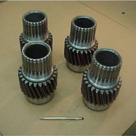
Gears play an essential role in the performance of many products that we rely on in our everyday lives. When we think about gears, we generally separate them into two categories: motion-carrying and power transmission. Motion-carrying gears are generally nonferrous alloys or plastics, while load bearing power transmission gears (Figure 1) are usually manufactured from ferrous alloys and are intended for heavy-duty service applications.
Figure 1. Typical off-highway truck power transmission gears | Image Credit: The Heat Treat Doctor®
Gear Materials & Engineering
Power transmission gears involve a wide variety of steels and cast irons. In all gears, the choice of material must be made only after careful consideration of the performance demanded by the application end-use and total manufactured cost, taking into consideration such issues as pre- and post-machining economics.
Key design considerations require an analysis of the type of applied load, whether gradual or instantaneous, and the desired mechanical properties, such as bending fatigue strength or wear resistance — all of which will define core strength and heat treating requirements.
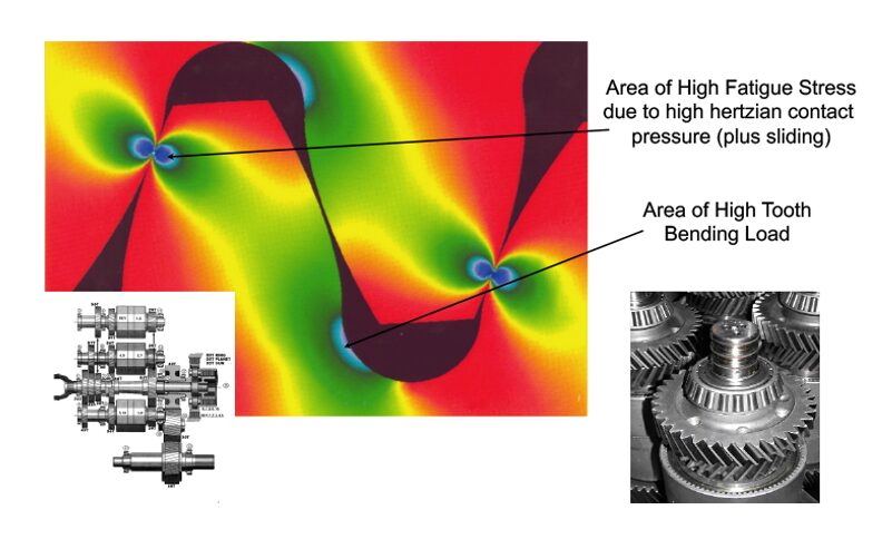
Figure 2. Stress profile in a heavy-duty transmission gear | Image Credit: The Heat Treat Doctor®
It is important for the designer to understand that each area in the gear tooth profile sees different service demands (Figure 2). Consideration must be given to the forces that will act on the gear teeth with tooth bending and contact stress, resistance to scoring and wear, and fatigue issues being paramount. For example, in the root area, good surface hardness and high residual compressive stress are desired to improve endurance or bending fatigue life. At the pitch diameter, a combination of high hardness and adequate subsurface strength are necessary to handle contract stress and wear and to prevent spalling.
Some of the factors that influence fatigue strength are:
Hardness distribution, a function of:
Case hardness
Case depth
Core hardness
Microstructure, a function of:
Retained austenite percentage
Grain size
Carbide size, type, and distribution
Non-martensitic phases
Defect control, a function of:
Residual compressive stress
Surface finish and geometry
Intergranular toughness
In the total manufacturing scheme, a synergistic relationship must exist between the material selection process, engineering design, and manufacturing (including heat treatment). A balance of the priorities in each discipline must be reached to achieve the optimization necessary for the ultimate performance of the gear design. This is often not an easy task.
Various atmosphere heat treatment methods are used for most types of gears including pre-hardening steps (e.g., annealing, normalizing, stress relief) and hardening processes (e.g., neutral hardening and case hardening).
Hardening
Neutral (aka through hardening) refers to heat treatment methods that do not produce a case. Examples of commonly through-hardened gear steels are AISI/SAE grades 1045, 4130, 4140, 4145, 4340, and 8640. It is important to note that hardness uniformity should not be assumed throughout the gear tooth. Since the outside of a gear is cooled faster than the inside, there will be a hardness gradient developed. The final hardness is dependent on the amount of carbon in the steel. The depth of hardness depends on the hardenability of the steel.
Through hardening can be performed either before or after the gear teeth are cut. When gear teeth will be cut after the part has been hardened, machinability becomes an important factor based on final hardness. The hardness is achieved by heating the material into the austenitic range, typically 815°C–875°C (1500°F–1600°F), followed by quenching and tempering.
Case Hardening
By contrast, case hardening is used to produce a hard, wear resistant case (surface layer) on top of a ductile, shock resistant interior (core). The idea behind case hardening is to keep the core of the gear tooth at a level under 40 HRC to avoid tooth breakage while hardening the outer surface to increase pitting resistance.
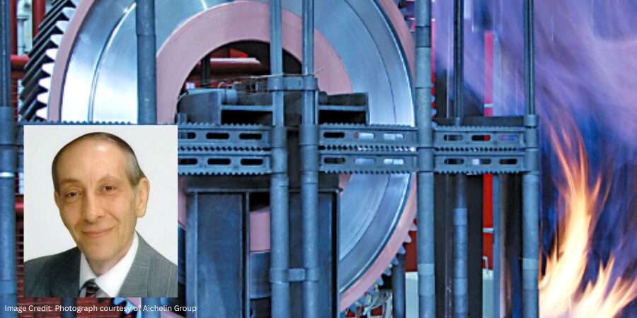
Carburizing
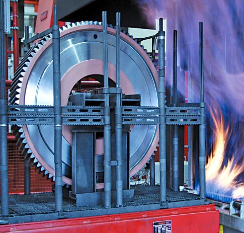
Figure 3. Atmosphere carburizing of large gears | Image Credit: Photograph courtesy of Aichelin Group
Atmosphere carburizing is the most common of the case hardening methods in use today and can handle a diverse range of part sizes and load configurations (Figure 3). In general, a properly carburized gear will be able to handle somewhere between 30–50% more load than a through-hardened gear. Examples of commonly carburized gear steels include AISI/SAE grades 1018, 4320, 5120, 8620, and 9310, as well as international grades, such as 20MnCr5, 17CrNiMo6, 18CrNiMo7-6, and 20MoCr4.
Atmosphere carburizing is typically performed in the temperature range of 870°C–955°C (1600°F–1750°F) although temperatures up to 1010°C (1800°F) are used for deep case work. Carburizing case depths can vary over a broad range, typically 0.13–8.25 mm (0.005–0.325 inches).
Carbonitriding
Carbonitriding is a modification of the carburizing process, not a form of nitriding. This modification consists of introducing ammonia into the carburizing atmosphere to add nitrogen to the carburized case as it is being produced. Examples of gear steels that are commonly carbonitrided include AISI/SAE 1018, 1117, and 12L14.
Carbonitriding is done at a lower temperature than carburizing, typically between 790°C–900°C (1450°F–1650°F), and for a shorter time. Combine this with the fact that nitrogen inhibits the diffusion of carbon, and what generally results is a shallower case than is typical for carburized parts. A carbonitrided case is usually between 0.075–0.75 mm (0.003–0.030 inches) deep.
Nitriding
Nitriding is another surface treatment process that has as its objective increasing surface hardness. One of the appeals of this process is that rapid quenching is not required, hence dimensional changes are kept to a minimum. It is not suitable for all gear applications; one of its limitations is that the extremely high surface hardness case produced has a more brittle nature than say that produced by the carburizing process. Despite this fact, in a number of applications, nitriding has proved to be a viable alternative. Examples of commonly nitrided gear steels include AISI/SAE 4140, 4150, 4340, and Nitralloy® 135M.
Nitriding is typically done in the range of 495°C–565°C (925°F–1050°F). Case depth and case hardness properties vary not only with the duration and type of nitriding being performed but also with steel composition, prior structure, and core hardness. Typically, case depths are between 0.20–0.65 mm (0.008–0.025 inches) and take from 10 to 80 hours to produce.
Nitrocarburizing (Ferritic or Austenitic)
Nitrocarburizing is a modification of nitriding, not a form of carburizing. In the process, nitrogen and carbon are simultaneously introduced into the steel while it is in a ferritic or at times an austenitic condition. A very thin “white” or “compound” layer is formed during the process, as well as an underlying “diffusion” zone. Like nitriding, rapid quenching is not required. Examples of gear steels that are commonly nitrocarburized include AISI/SAE grades 4140, 5160, 8620, and certain tool steels, such as H11 and H13.
Nitrocarburizing is normally performed at 550°C–600°C (1025°F–1110°F) and can be used to produce a 58 HRC minimum hardness, with this value increasing dependent on the base material. White layer depths range from 0.0013–0.056 mm (0.00005–0.0022 inches) with diffusion zones from 0.03–0.80 mm (0.0013–0.032 inches) being typical.
In Summary
There are many ways to heat treat gears. While atmosphere heat treatment (discussed above) is perhaps the most widely used technology today, other types of heat treatments, namely vacuum and induction hardening, are becoming more and more common methods. These will be discussed in Part Two.
About the Author
Dan Herring “The Heat Treat Doctor” The HERRING GROUP, Inc.
Dan Herring has been in the industry for over 50 years and has gained vast experience in fields that include materials science, engineering, metallurgy, new product research, and many other areas. He is the author of six books and over 700 technical articles.
G.S. Precision, a precision machining and manufacturing company headquartered in Brattleboro, Vermont, has expanded its global manufacturing platform with the announcement of the acquisition of Lush Heat Treatment Ltd. and Headwater Precision, Inc., strengthening vertical integrated capabilities that support aerospace, defense, and other high-spec industries. The additions broaden the company’s technical scope across machining, coatings, and thermal processing, while extending the company’s geographic footprint in North America and Europe.
James R. Callan Chief Executive Officer G.S. Precision
Lush Heat Treatment, based in the United Kingdom, provides vacuum and endothermic heat treating services, as well as brazing services, for clients in the aerospace, defense, space, and nuclear power sectors. These processes support the performance requirements of critical components operating in demanding environments.
Headwater Precision, located in New Hampshire, is a precision manufacturing and advanced coating technologies business serving clients in aerospace defense, semiconductor, and industrial markets.
By bringing these capabilities together, G.S. Precision is positioning its company to offer a more integrated manufacturing approach, combining machining, surface treatment, and heat treating within a single organizational structure.
James R. Callan, chief executive officer of G.S. Precision, said the acquisitions align with the company’s growth strategy, adding capabilities such as advanced coatings and specialized heat treating to better support clients producing mission-critical components.
Press release is available in its original form here.
What do aerospace and industrial heating vessels have in common? Backups for essential systems. In this Technical Tuesday installment, Bruce Yates, president of Protection Controls Inc., explores how NFPA 86 Standard for Oven and Furnaces addresses redundant flame safety, compares common sensing approaches, and highlights recent advances in UV scanner technology that improve reliability and reduce maintenance risks.
This informative piece was first released in Heat Treat Today’sFebruary 2026 Air & Atmosphere Heat Treating print edition.
Introduction
Boeing Aircraft lost billions of dollars before realizing that the 737 MAX’s MCAS (Maneuvering Characteristics Augmentation System) needed a redundant angle-of-attack vane to prevent erroneous MCAS-induced drive commands. Lockheed Martin uses dual-redundant MIL-STD-1553 data bus (that is, a shared communication pathway for exchanging data between electronic systems) on its Apache Guardian attack helicopter for target acquisition and cueing for the helicopter’s fire-control radar system. Spacecraft internal Active Thermal Control Systems (ATCSs) can either be a fully redundant thermal-control loop or a single loop system that is equipped with a redundant accumulator to be activated if needed. The accumulator represents a single point of failure that can result in a loss of crew.
Aerospace is not the only industry where redundancy is an important aspect of safety. It is critical in the industrial heating industry. NFPA 86 Standard for Ovens and Furnaces has for many years required redundant pilot gas valves and redundant main gas valves.
Let’s discuss redundant flame safety.
Redundancy in Industrial Heating
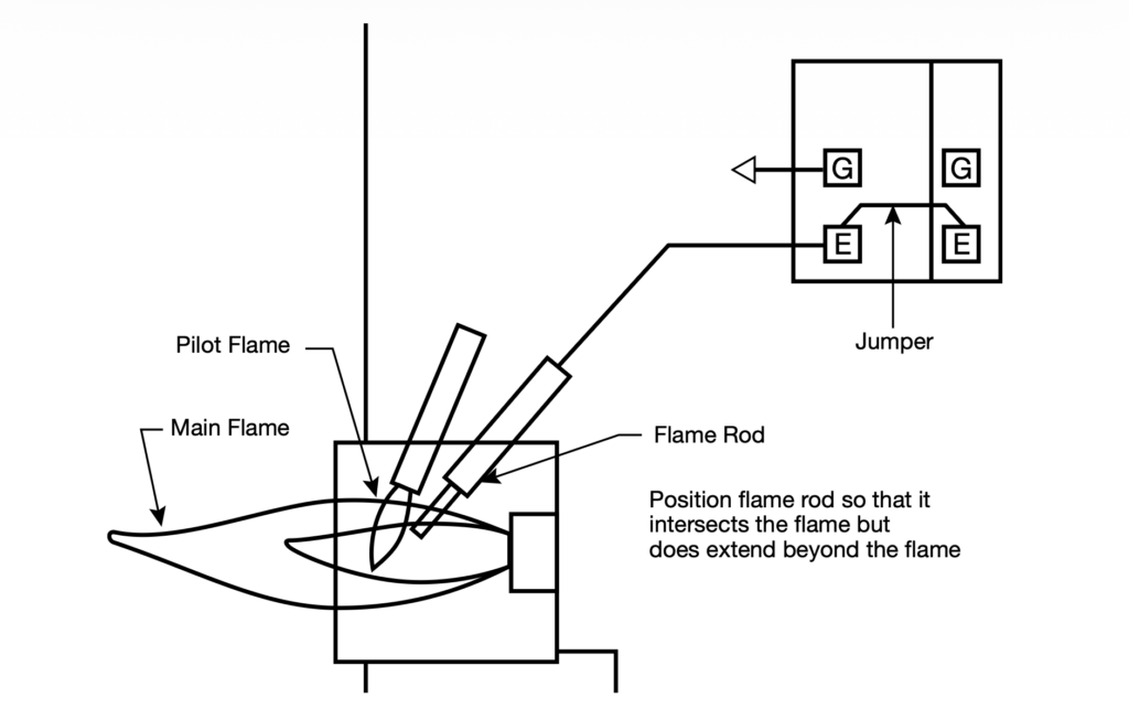
There are two types of flame sensors generally used on industrial burners: flame rods and ultraviolet scanners. Flame rods are simply stainless steel rods that intersect the burner flame. A voltage potential from the combustion safeguard is applied to the flame rod. When a flame is present, an electrical current (measured in millionths of an amp) flows from the flame rod through the ionized gases of the flame to the burner, which is grounded. This current is amplified in the combustion safeguard and energizes a relay output to power the fuel valves (see Main Image).
Redundancy can be achieved by using a two-burner control with one flame rod. The flame signal from the flame rod goes to the sensor input of both positions of the two-burner control (Figure 1).
We will devote the rest of this article to UV scanners (Figure 3).
Figure 1. Redundant flame safety with a single burner flame safeguard with a flame rod sensor
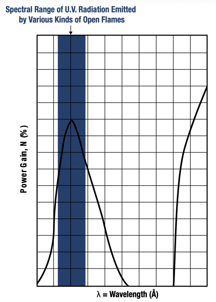
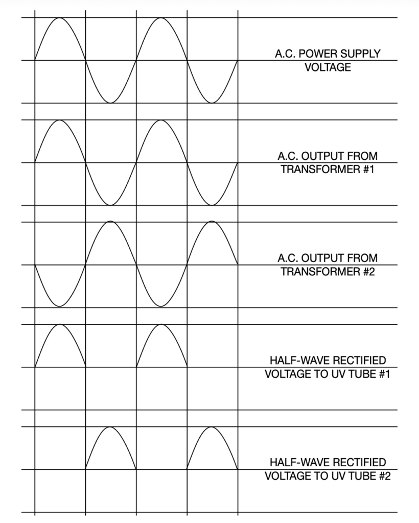
Figure 2. Solar radiation begins at approximately 2,800 Å and is therefore not detectable by the flame rod sensor.Figure 3. Demonstration of two independent UV tubes producing UV rays out of sync with one another | Image Credit: Protection Controls
Redundant Flame Safety with UV Scanners
The tube of a UV scanner responds only to radiation in the spectrum of 1,900 to 2,300 Å (Figure 2). Peak response is at 2,100 Å (210 nm). Solar UV starts at about 2,800 Å, as shown in Figure 2, and is therefore not detectable by the device. Solar radiation, of course, extends into the visible spectrum (4,000 Å) and extends into the infra-red spectrum. A UV tube consists of a fused silica or UV glass envelope, two electrodes, and a gas contained in this envelope. This is called a cold-cathode gas-discharge tube.
This tube conducts or ignites when it is irradiated with ultraviolet light and when sufficient voltage potential exists across the two electrodes. The electrodes can be made of tungsten, molybdenum, or nickel. When a photon of sufficient energy is absorbed into the cathode electrode, electrons are emitted and are drawn to the anode. A larger cathode allows more electrons to avalanche, causing higher current flow and thus higher sensitivity to UV. There are high sensitivity UV scanners designed for special burners that will produce low UV, such as one designed by Protection Controls, Inc.
The gas in the tube is usually a helium-hydrogen ionizable mix. Electrons released by the cathode release electrons in the ionized gas, becoming a self-sustaining discharge much greater than that of the originally generated electrons and producing a very high current gain or avalanche effect. The sensitivity of a tube will very slowly decrease over a period of time. Replacement should be made after 8,000 hours of operation. The current produced by the photoelectrons is measured in millionths of an ampere, so this current is amplified in the combustion safeguard to energize a relay that can then energize the fuel valves.
Critical Maintenance to Avoid Tube Gas Contamination
While UV scanners are very reliable, tube gas contamination may occur with large temperature shock (ΔTEMP/ΔTime) or large physical shock (a 2-inch drop may cause 100G shock), causing the electrode to UV glass envelope seal integrity to be compromised. Because of this, it is possible for a UV tube to conduct current when no UV is incident upon it. This would normally be detected during the flame safeguard safe start check. When an indicated flame on condition exists prior to purge or ignition, the safe start check relay prevents ignition and gas valve energization.
In addition to safe start check before every heating cycle, a monthly preventative maintenance schedule should be in place if the burner is used daily. This consists of closing a manual gas valve. The electrically powered gas valves should close in two to four seconds as the UV scanner and combustion safeguard respond to loss of flame.
If a burner is in continuous service, we recommend that this maintenance schedule be performed weekly. An alternative to this is to use a self-checking ultraviolet scanner and control. In the past, this type of scanner involved an electrically operated shutter, which alternately would block and allow UV to the tube. However, having a mechanical device operating close to the burner heat and vibration is a recipe for frequent and premature failures; it is typically rated for only 140°F to 175°F maximum and is quite expensive.
Going Shutterless
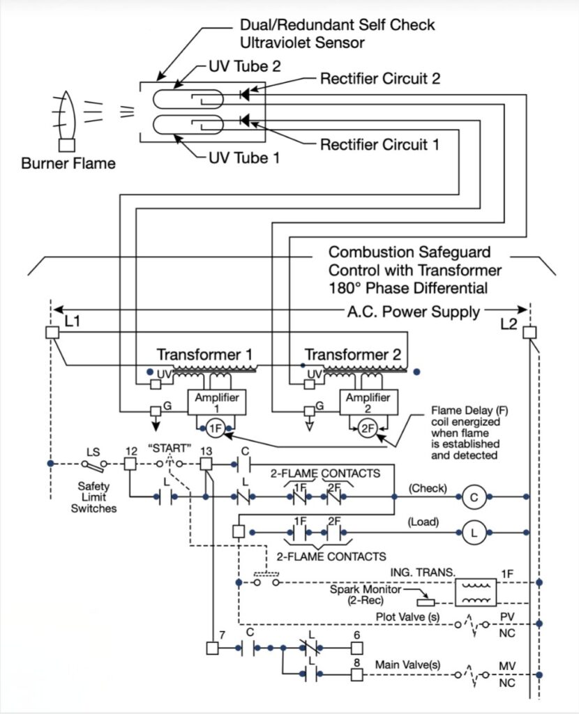
Figure 4. Note how each amplifier has its own flame relay | Image Credit: Protection Controls
Newer designs are available that completely avoid using a mechanical operating device to moderate the UV, increasing reliability and durability. For example, the Dual/Redundant Self Check UltraViolet Flame Sensor and Combustion Safeguard Control from Protection Controls includes two UV tubes in one ultraviolet sensor to monitor one burner flame. UV tubes respond to welding sparks, ignition sparks, lightning, bright incandescent or fluorescent light, solar radiation, gamma rays, and x-rays.
Since UV tubes produce UV rays when they conduct, two UV tubes in one sensor would not normally be suitable for sensing a burner flame, as one UV tube could be responding to the other tube and not the flame. But in the case of this safety control, two voltage supplies to the UV tubes are out of phase with each other. When one UV tube is powered and may respond to UV rays, the other UV tube is off. Additionally, the two UV tubes are powered through two rectifier circuits from two transformers that are out of phase with each other. The two UV tubes are powered and sense UV from the flame on alternating half cycles (Figure 3).
Each UV tube and rectifier circuit provides input to its amplifier. Each amplifier provides input to its own flame relay (Figure 4). Upon burner startup, before burner ignition, if either UV tube is in conduction, the safe start check circuit does not permit powering the fuel valve.
During the burner run cycle, if either UV tube fails in the conduction state, the cycle will safely continue with the other UV tube sensing the burner flame. See Figure 5.
Regardless of which sensor option you choose, accounting for flame redundancy and ensuring your maintenance plan is proactive enough for the method chosen is key to a safe manufacturing environment.
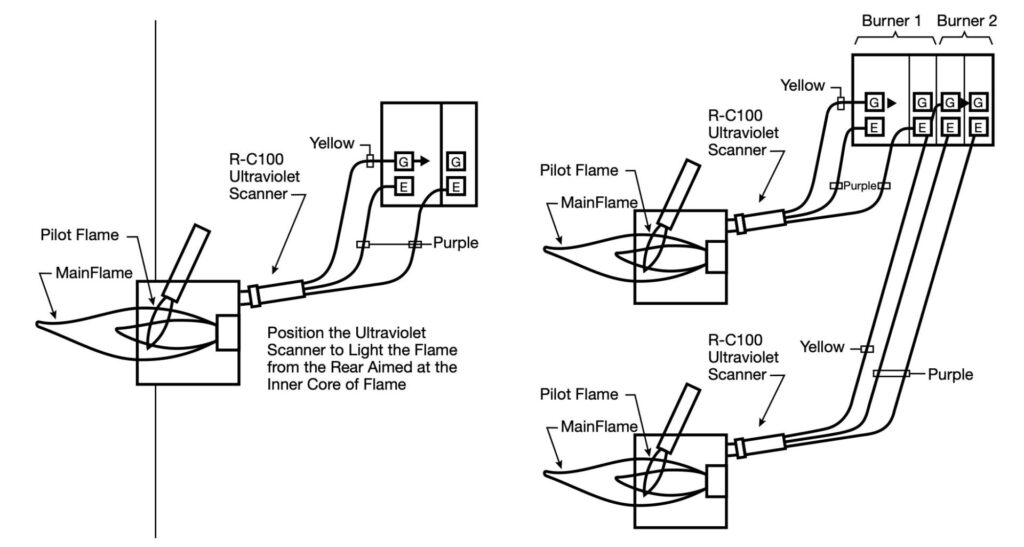
Figure 5. Redundant flame safety for single- and multi-burner flame safeguards: (a) redundant flame safety with a single burner flame safeguard with an ultraviolet sensor and (b) redundant flame safeguard (2-burner shown) with an ultraviolet sensor. | Image Credit: Protection Controls
About The Author:
Bruce Yates President Protection Controls, Inc.
Bruce Yates is the president of Protection Controls and is involved with management, sales, and engineering responsibilities. He graduated from the University of Illinois with a Bachelor of Science in Electrical Engineering in 1968. He works with his brother Douglas in the family-owned flame safeguard control manufacturing company, started by his father, James, and uncle, Robert, in 1953.
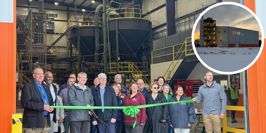
A new production facility for lightweight refractory materials has opened in Missouri, increasing supply for furnace-lined industrial processes that operate at elevated temperatures. The materials support thermal insulation and durability in equipment used across sectors such as petrochemicals, aluminum, and power generation, where reliable furnace performance is essential to high-temperature manufacturing and other heat-intensive processing operations.
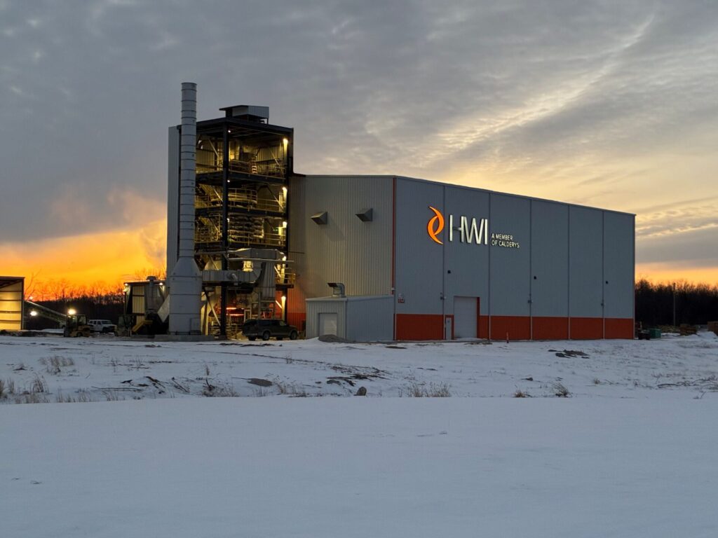
The new lightweight monolithics production facility in Fulton | Image Credit: HWI
HWI, a member of Calderys, has opened a lightweight monolithics production facility in Fulton, Missouri. Built on existing HWI property at the company’s Rotary Kiln complex, the greenfield investment increases production capacity for lightweight refractory materials used to line heaters, reformers, boilers, crackers, and furnaces in a range of industrial applications.
The facility has direct access to local clay reserves, enabling vertical integration intended to support raw material consistency and supply reliability. Operational features include a furnace system used to produce GREENLITE® aggregate, along with robotic automation for packaging and material handling, as well as updated packaging capabilities.
Michel Cornelissen President and CEO Calderys Group
The added capacity is expected to shorten lead times, support make-to-stock inventory, and allow the company to pursue larger projects that were previously limited by supply constraints. Premium GREENLITE® products, including the GREENLITE®-45-L family of monolithics and GREENLITE® 115 AR brick, are now shipping through the company’s distribution network.
“Demand for these high-performance, energy-saving lightweight refractories continues to grow rapidly while global supply chains remain under pressure,” said Michel Cornelissen, president and CEO of Calderys Group.
Monolithic refractories provide insulation and structural stability for equipment operating in high-temperature environments. HWI’s GREENLITE® lightweight monolithics provide insulation with optimized strength-to-density ratios that help minimize heat loss, reduce fuel consumption and CO2 emissions, extend campaign life, and enable longer service intervals. These, in turn, help clients lower operating costs and improve energy efficiency while maintaining productivity and reliability.
Press release is available in its original form here. Main image shows the ribbon cutting with local officials at the Fulton plant. Image Credit: HWI
Heat TreatToday offers News Chatter, a feature highlighting representative moves, transactions, and kudos from around the industry. Enjoy these 22 news items, including Advanced Heat Treat Corp.’s expansion of induction hardening and gas nitriding capacity in Alabama, Dauch Corporation’s acquisition of Dowlais Group, CAN-ENG Furnaces International’s new certification as a FANUC Authorized System Integrator, and more!
Equipment
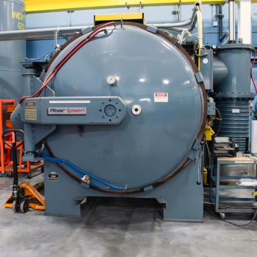
1. Urschel Laboratories, a manufacturer of precision food-cutting equipment, has ordered a new MetalMaster HR vacuum furnace from Ipsen USA to support in-house heat treating of stainless steel components used in its machines. The system will replace a furnace that has been operating since 1986 and marks Urschel’s sixth furnace purchase from Ipsen, reflecting a decades-long partnership. The upgrade is expected to strengthen Urschel’s manufacturing efficiency and product reliability, reinforcing equipment performance across the global food processing industry it serves.
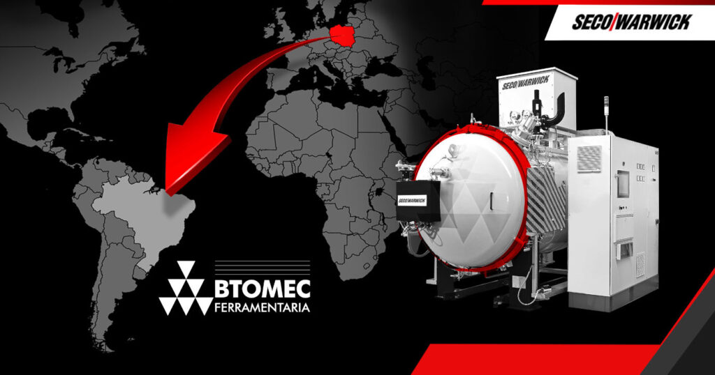
2. BTOMEC Ferramentaria e Usinagem de Precisão Ltda., a manufacturer of multi-cavity injection molds, has invested in a Vector vacuum furnace from SECO/WARWICK to bring die and tooling hardening in-house. The move enables the company to reduce reliance on external heat treaters while gaining greater control over production timelines, costs, and quality. The investment reflects a broader industry trend of manufacturers establishing internal heat treat capabilities as production volumes grow.
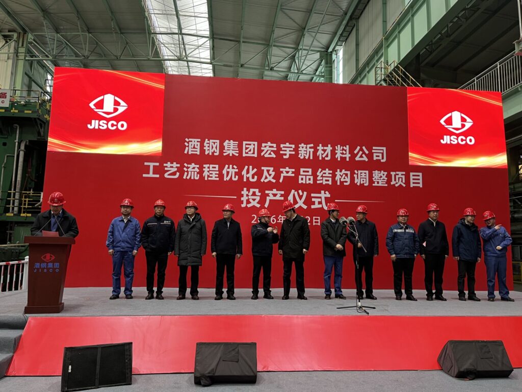
3. JISCO Carbon Steel has commissioned a new integrated CSP®-HSM production line at its Jiayuguan facility, combining Compact Strip Production casting with a hot strip mill in a fully automated system supplied by SMS Group. The upgrade doubles the plant’s annual production capacity from about 2 million to 4.5 million tons while improving operational flexibility and process integration between casting and rolling. The project strengthens JISCO’s ability to deliver consistent flat-steel products for global manufacturing markets.
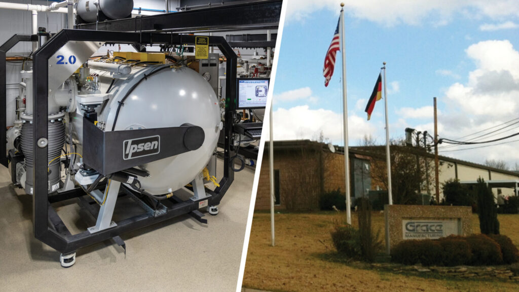
4. Grace Manufacturing has installed a new TITAN H2 vacuum furnace from Ipsen at its Russellville, Arkansas facility to expand heat treating capabilities for thin martensitic stainless steel components used in medical devices. The system replaces an aging furnace and was selected after third-party testing confirmed it met the company’s processing requirements. The upgrade strengthens production reliability and metallurgical control for precision medical manufacturing.
5. An international aircraft motion-control manufacturer has ordered an additional low-temperature vacuum tempering furnace from SECO/WARWICK’s U.S. subsidiary to expand its heat treat capacity for precision aerospace components. The system will support tempering, aging, and other sub-critical heat treat processes while meeting stringent aerospace thermal-processing standards.
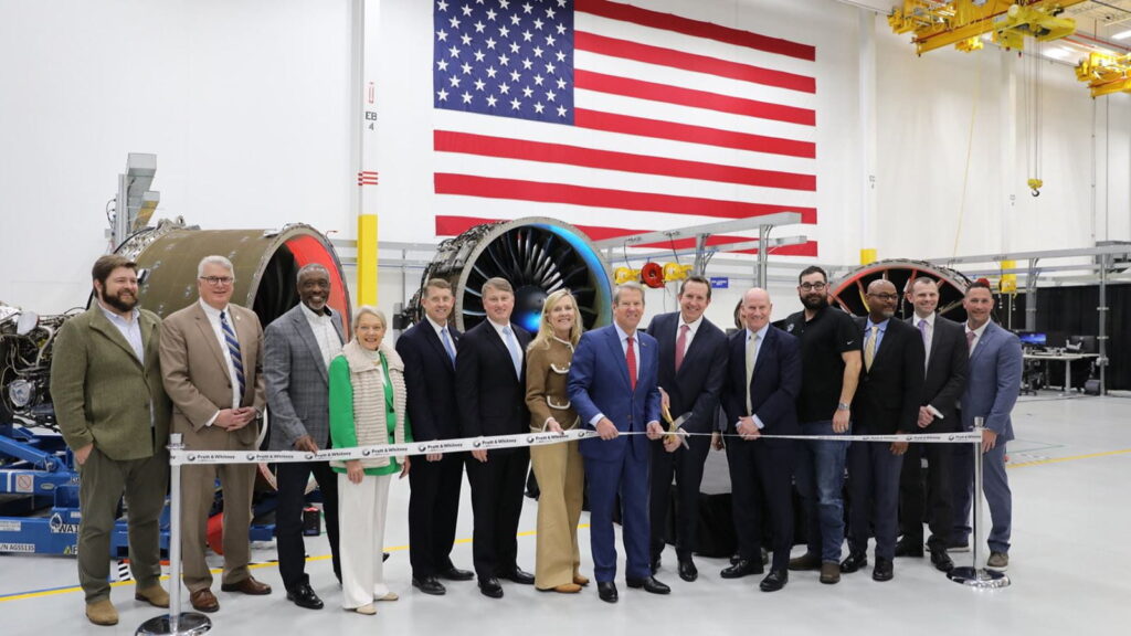
6. Pratt & Whitney, an RTX business, is investing $200 million to expand its Columbus, Georgia, manufacturing site with a seventh isothermal forging press to produce rotating compressor and turbine disks for commercial and military jet engines. The new equipment is expected to increase output of these critical engine components by about 30% and is scheduled to be operational in 2028. The expansion strengthens production capacity for next-generation aerospace engine programs and supports growing global demand for aircraft propulsion systems.
7. A defense-sector firearm manufacturer has selected a vacuum furnace system from SECO/WARWICK to support carburizing and heat treatment of steel components used in firearm production. The new equipment will enhance control over case hardening processes, helping improve durability and performance of critical firearm parts. The investment strengthens thermal processing capacity within the defense manufacturing supply chain.
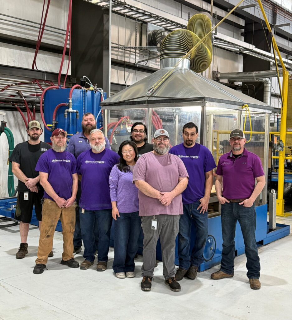
8. Advanced Heat Treat Corp. (AHT) has expanded induction hardening and gas nitriding capacity at its Cullman, Alabama facility, adding a larger induction system and an additional nitriding unit. The upgrade enables the processing of larger and more complex components while supporting higher production volumes. The investment strengthens surface hardening capabilities for manufacturers by improving throughput and maintaining fast turnaround times for industrial parts.
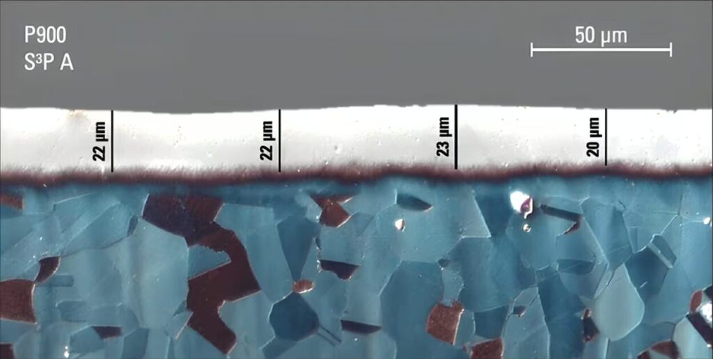
9. Bodycote has installed a new diffusion hardening treatment vessel at its Mooresville, North Carolina facility, expanding stainless steel processing capabilities in North America. The system enables the company to surface-harden larger components using its ADM® low-temperature diffusion hardening process. The investment broadens capacity for industries such as oil and gas, food and beverage, and medical technology by improving durability of stainless steel parts while maintaining corrosion resistance.
10. Gasbarre Thermal Processing Systems will supply a custom-engineered box furnace and loading system to a U.S. government manufacturing facility to expand a previously validated high-temperature thermal process. The system, designed to meet strict space and operational constraints, will operate up to 2100°F in an air atmosphere and represents the largest configuration the facility can accommodate. The installation enables the government manufacturer to scale production while maintaining specialized thermal processing capabilities.
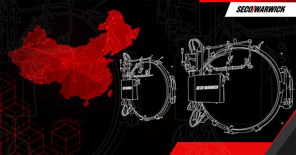
11. A China-based manufacturer of vacuum circuit breakers has ordered two vacuum furnaces from SECO/WARWICK to add vacuum brazing capability for producing vacuum interrupter components used in power distribution systems. The installation expands the manufacturer’s ability to produce brazed, hermetically sealed interrupter assemblies used in circuit breakers that interrupt electrical current in industrial and utility power networks.
12. PSW Group has opened a new High Integrity Diecasting Center at its Magretech plant in Bellevue, Ohio, focused on semi-solid casting technologies for aluminum and magnesium components. Led by Dr. Tao Wang, the facility allows OEMs, Tier 1 suppliers, and die casters to trial, develop, and scale advanced casting processes using semi-solid and high-pressure die-casting methods. The center aims to accelerate development of lighter, stronger, and lower-carbon metal components, supporting innovation and faster time-to-market across the automotive and light-metal manufacturing sectors.
Ipsen MetalMaster furnace originally commissioned in 1986 awaiting replacement at UrschelBTOMEC’s Vector vacuum furnace order from SECO/WARWICKCommissioning ceremony on February 2, 2026, at JISCO’s site
An Ipsen TITAN H2 vacuum furnace for Grace ManufacturingRibbon cutting at Pratt & Whitney’s Columbus, Georgia facilitySECO/WARWICK vacuum tempering furnace for aerospace componentsA new SECO/WARWICK furnace strengthening the defense manufacturing supply chainAHT Employees in Front of Induction Unit in AlabamaMicrostructure of surface hardened stainless steel AIS1660 (1.4980) | Image Credit: BodycoteCustom-engineered box furnace from Gasbarre Thermal Processing SystemsVacuum furnaces for a vacuum circuit breaker manufacturerPSW Group’s High Integrity Diecasting Center in Bellevue, OH
Company & Personnel
13. Dauch Corporation has completed its acquisition of Dowlais Group plc, bringing together major automotive manufacturing operations including GKN Automotive and GKN Powder Metallurgy. The combined company expands global capabilities in driveline systems, metal forming, and powder metallurgy under the leadership of CEO David C. Dauch. The move strengthens supply and engineering capacity for internal combustion, hybrid, and electric vehicle platforms across the global automotive industry.
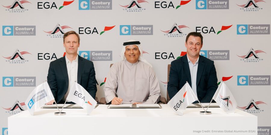
14. U.S. Aluminum Company has signed an agreement with Emirates Global Aluminum (EGA) and Century Aluminum to explore building a downstream aluminum fabrication facility in Inola, Oklahoma, near a planned primary aluminum smelter. The proposed plant would convert molten aluminum into value-added products for sectors such as electrical, defense, aerospace, automotive, and machinery manufacturing. The project aims to strengthen U.S. aluminum supply chains and help expand domestic primary aluminum production capacity.
15. The AICHELIN Group has appointed Daniel Panny as head of United Process Controls (UPC) in Göppingen and Mike Löpke as head of QMULUS in Düsseldorf as part of organizational changes following the integration of NITREX. The leadership updates strengthen the group’s focus on automation, plant control, and IIoT-driven digital solutions for heat treatment operations. The move supports closer integration of furnace technology, process expertise, and data-driven optimization across the global heat treat industry.
16. SECO/WARWICK has appointed Pan Gaojun as managing director of SECO/WARWICK China, following a succession process within the company. Gaojun, who joined the group in 2010, will lead operational development and strengthen the company’s presence in key technologies such as CAB lines and vacuum furnaces in the Asian market. The leadership change is intended to support continued growth and strengthen SECO/WARWICK’s position in China’s expanding heat treat and thermal-processing sector.
17. Vienna-based refractory manufacturer RATH AG has appointed Christian Morawetz as chief operating officer, bringing the experienced operations executive onto its Executive Board to oversee production, purchasing, R&D, quality management, and IT across the company’s global manufacturing operations. Morawetz’s leadership and industrial management experience are expected to strengthen operational efficiency and innovation as the company undertakes a broader transformation of its product portfolio and production structures to better serve high-temperature industries such as steel, glass, and ceramics.
CEO David C. DauchU.S. Aluminum, EGA, and Century Aluminum signing agreement to strengthen planned Oklahoma aluminum fabrication hubNewly appointed head of UPC Daniel Panny and newly appointed head of QMULUS Mike Löpke
Change of leadership at SECO/WARWICK China with newly appointed managing director Pan GaojunNewly appointed RATH AG COO Christian Morawetz
Kudos
18. The U.S. Department of War (formerly Department of Defense) has awarded contracts through the Defense Logistics Agency to 24 manufacturers to supply additively manufactured metal and polymer parts under the Joint Additive Manufacturing Acceptability (JAMA) IV pilot program. The firm-fixed-price IDIQ contract, valued at up to $9.8 million with a base period through Feb. 2027, allows the Pentagon to issue task orders for 3D-printed components supporting U.S. military programs.
19. CAN-ENG Furnaces International Ltd. has been certified as a FANUC Authorized System Integrator, expanding its capabilities in robotic automation for industrial furnace and thermal-processing systems. The certification allows CAN-ENG to design and integrate FANUC robots into heat treat operations, including material handling and high-volume furnace automation. The partnership strengthens automation options for manufacturers seeking greater efficiency, reliability, and safety in heat treat and thermal processing environments.
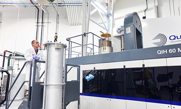
20. Burloak Technologies Inc., based in Oakville, Ontario, has completed its latest Nadcap audit, enabling its heat treatment capabilities to support demanding industries. The certification reinforces the company’s thermal processing services — including hot isostatic pressing (HIP), vacuum heat treatment, and alloy heat treat cycles — used in sectors such as aerospace, defense, automotive, and medical manufacturing.
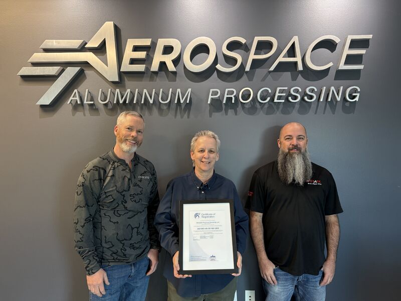
21. Stack Metallurgical Group announced that its Salt Lake City facility, Aerospace Aluminum Processing (ASAP), has achieved AS9100D certification following an audit completed with zero findings. The accreditation strengthens the facility’s quality credentials for aerospace aluminum heat treating and related processing, reinforcing its role in supporting high-spec aerospace manufacturing and positioning other Stack facilities to pursue similar approvals.
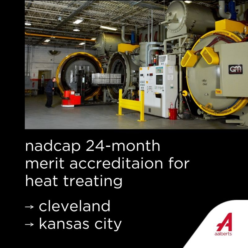
22. Aalberts surface technologies announced that its Cleveland, Ohio, and Kansas City facilities have earned Nadcap 24-Month Merit Accreditation for heat treating, effective February 10, 2026. The designation — achieved after years of near-zero audit findings and strict AMS2750 pyrometry compliance — signals strong process discipline and quality systems for aerospace heat treat operations, helping reduce supplier risk and strengthen reliability across the aerospace manufacturing supply chain.
FANUC Authorized System Integrator certification for CAN-ENG FurnacesNadcap-certified Burloak Ontario facilityStack Metallurgical Group’s Aerospace Aluminum Processing receiving its AS9100D certificationAalberts surface technology’s Cleveland and Kansas City facilities earning their Nadcap 24-Month Merit Accreditation for heat treating
We’re celebrating getting to the “fringe” of the weekend with a Heat TreatFringe Fridayinstallment: the U.S. Department of War (formerly Department of Defense) has awarded contracts to two dozen U.S. manufacturers to produce additively manufactured metal and polymer parts for defense programs. The contracts were issued through the Defense Logistics Agency (DLA) as part of the Joint Additive Manufacturing Acceptability (JAMA) IV pilot parts program.
While not exactly heat treat, “Fringe Friday” deals with interesting developments in one of our key markets: aerospace, automotive, medical, energy, or general manufacturing.
The Pentagon has awarded contracts to produce additively manufactured metal and polymer parts for defense programs. The awards, issued through the Defense Logistics Agency as part of the Joint Additive Manufacturing Acceptability (JAMA) IV pilot parts program, allow the Department of Defense to issue task orders to 24 participating manufacturers capable of producing parts using additive manufacturing technologies.
The awards are structured as a firm-fixed-price, indefinite-delivery/indefinite-quantity (IDIQ) contracts with a maximum value of approximately $9.8 million. The contract includes a one-year base period running through February 24, 2027, with four one-year option periods.
The JAMA IV pilot parts program supports the procurement of additively manufactured components for U.S. military clients, including the Army, Navy, Air Force, and Marine Corps. By awarding contracts to multiple manufacturers, the program establishes a pool of suppliers eligible to compete for task orders related to additively manufactured parts.
A manufacturer of vacuum circuit breakers has added vacuum brazing capability for producing electrical power components utilized in modern power distribution systems. The thermal processing technology joins metal parts used in vacuum interrupters, helping ensure consistent performance in circuit breakers used across industrial and utility power networks.
Image Credit: SECO/WARWICKMaciej Korecki Vice President of Vacuum Business Segment SECO/WARWICK
The manufacturer, based in China and specializing in multiple types of vacuum circuit breakers, ordered two vacuum furnaces from SECO/WARWICK, a global manufacturer of industrial heat treatment equipment with operations in North America. The client has previously installed multiple systems from SECO/WARWICK. “We have [clients] who operate more than a dozen of our systems,” said Maciej Korecki, vice president of the Vacuum Furnace Segment at SECO/WARWICK Group.
The furnaces will be used primarily for vacuum brazing and related thermal processing of interrupter assemblies and other circuit breaker components that require strict control of mechanical strength, hermetic sealing, and dimensional stability.
The systems use a pumping configuration with a turbomolecular pump designed to achieve ultra-high vacuum conditions. High temperature uniformity and rapid heating — enabled by seven control zones, including a central heating element — allow for consistent processing of loads. The furnaces are also equipped with a horizontal gas-cooling system and an external cooling unit.
As a critical component in circuit breakers, vacuum interrupters play a key role in safely interrupting electrical current during switching operations. The addition of vacuum brazing capability and controlled vacuum furnace processing allows the manufacturer to produce the sealed assemblies required for reliable performance in power distribution equipment.
Press release is available in its original form here.
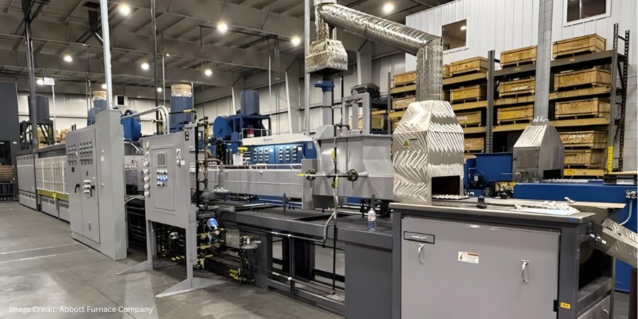
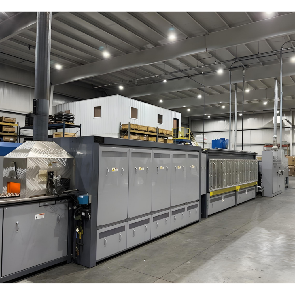
Metco Industries has added a new seven-zone continuous belt sintering furnace to improve process control and consistency in the production of powdered metal components. The installation supports tighter thermal processing parameters and enhanced monitoring capabilities, helping ensure repeatable results for parts used across industrial manufacturing applications.
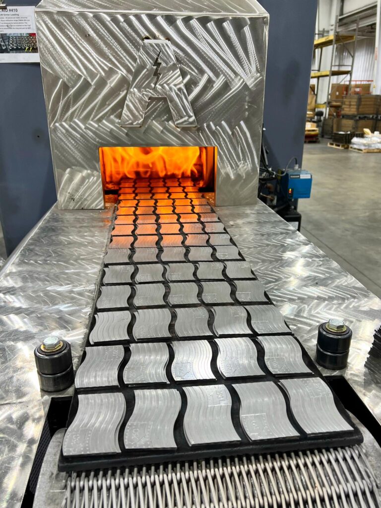
Continuous belt furnace installed at Metco Industries incorporating fully digital atmosphere control technology developed in-house at Abbott Furnace Company | Image Credit: Abbott Furnace CompanyParts entering the sintering furnace | Image Credit: Abbott Furnace Company
The furnace was engineered and manufactured by Abbott Furnace Company, incorporating fully digital atmosphere control technology developed in-house. Digital flow control, advanced monitoring, and data-driven diagnostics allow operators at Metco to track furnace performance in real time and adjust sintering conditions as needed.
The technology is designed to improve repeatability and provide greater visibility into furnace operations. These capabilities allow manufacturers to optimize thermal processing conditions and maintain more consistent production outcomes.
Press release is available in its original form here. Main image shows the full seven-zone continuous belt furnace installed at Metco Industries. Image Credit: Abbott Furnace Company
When a load hangs up during quenching, seconds matter and improvised decisions can escalate risk. In this Technical Tuesday installment, Bruno Scomazzon, general manager of Precision Heat Treat Ltd., outlines a step-by-step emergency response procedure for exactly this scenario, which is one of the most dangerous in atmosphere heat treating. Drawing on real-world experience, this guide is intended to help companies develop their own effective procedures for maintaining safety, controlling furnace conditions, and coordinating with emergency responders in high-risk situations.
This informative piece was first released in Heat Treat Today’sFebruary 2026 Annual Air & Atmosphere Heat Treating print edition.
Scenario Overview
A load has been transferred to the quench and the elevator is lowering into the oil, but the load becomes hung up and fails to fully submerge. The inner door successfully closes, and the outer (front) door remains closed.
This is an extremely high-risk situation requiring strict adherence to emergency procedures. The goal is to protect: first the personnel (minimize the chance of injury or escalation of the situation), then the facility, and finally the equipment.
1. Immediate Actions
DO NOT Open Outer Door
There may be a natural urge to assess the situation but resist temptation. DO NOT stand in front of or directly beside the outer door and never open it during an active hang-up. Opening this door can introduce oxygen to a hot chamber, causing:
Explosions or flash fires.
Loss of containment due to door warping or mechanical failure.
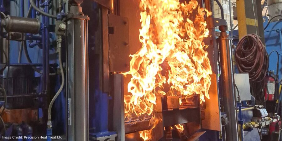
In extreme cases, the outer door may be compromised (blown off, stuck open, or partially open) with visible flames. This warrants immediate escalation to the fire department.
If Outer Door Cannot Be Closed
In this scenario, immediately notify the fire department and advise them to prepare for a foam response. DO NOT allow the use of water. This may trigger violent reactions with oil or atmosphere and spread the fire!
Internal trained responders should:
Don PPE.
Retrieve fire suppression gear.
Be ready to protect critical systems until responders arrive.
DO NOT shut down the furnace.
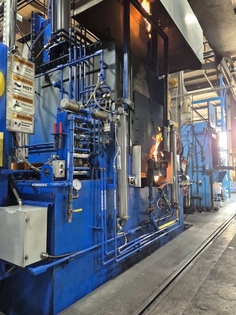
Figure 1. Atmosphere furnace during normal operation | Image Credit: Precision Heat Treat Ltd.Figure 2. Vestibule door partially opened during a controlled simulation to illustrate gas release behavior — not an actual incident | Image Credit: Precision Heat Treat Ltd.
2. Maintain Electrical Power
To ensure essential systems stay active, you must maintain electrical power. Ensure these systems stay active:
Set the furnace cycle to manual mode from auto mode. This will bypass any PLC sequencing from auto cycling doors, elevators, and handlers.
Keep the pilots lit.
Keep the oil cooler running to prevent tank overheating.
Shut off oil heaters to prevent additional heat loading in the quench tank.
Keep quench agitation on low during the entire period to assist in lowering the temperature at the interface surface area between the hot load and the oil. This prevents stratification and dissipates radiant heat into the oil.
Keep the recirculating fan running.
Keep the instrumentation functioning for monitoring.
NOTE: Loss of these systems eliminates visibility, atmosphere control, and safe response options.
3. Atmosphere Management
Maintain a protective atmosphere and positive furnace pressure to prevent oxygen ingress and uncontrolled combustion:
Set the carbon control to “0”.
Shut off the enriching gas.
Shut off the ammonia.
Shut off the dilution air.
Nitrogen Purge
These steps depend on whether a nitrogen purge is available; it is highly advised that nitrogen purge be available for all IQ or straight through units. Be sure you understand how long it takes for your specific furnace to fully purge endothermic gas. While NFPA 86 recommends five volume turnovers, some experts advise planning for up to ten per hour in an emergency. Each furnace should have established purge data under normal conditions so operators can act with confidence when time is critical.
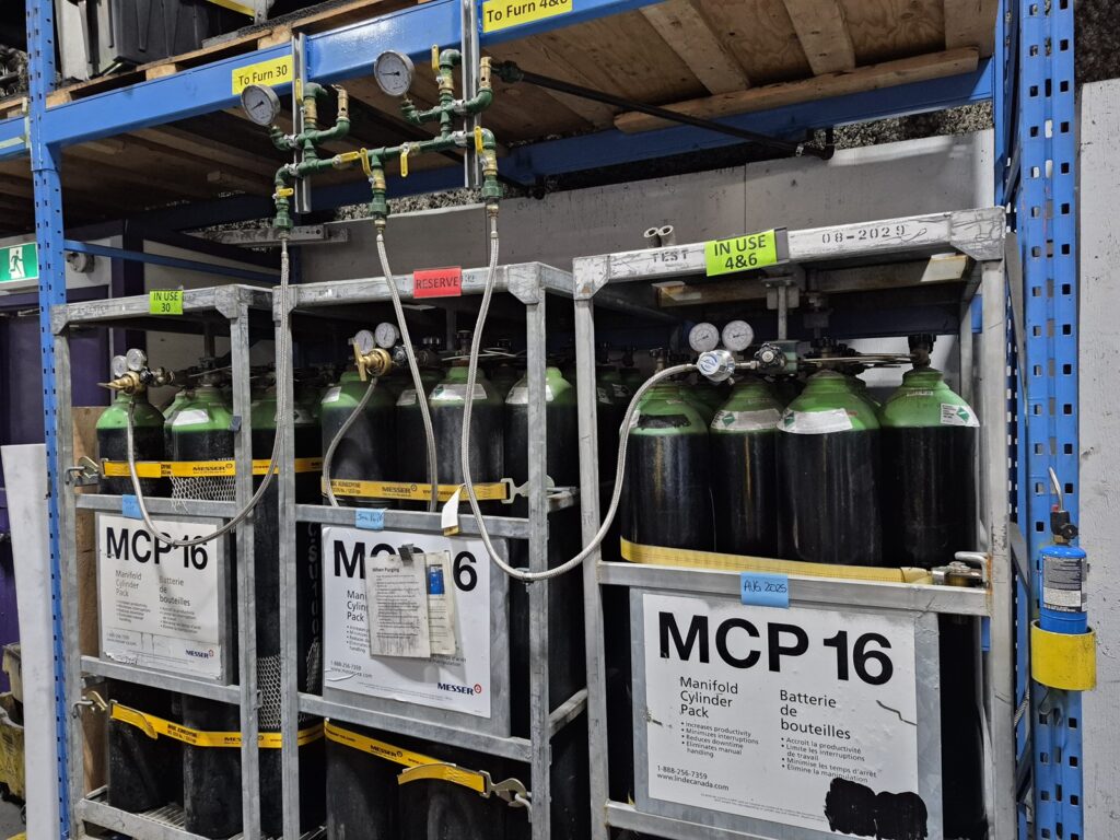
Figure 3. Bulk nitrogen supply used for emergency purging and atmosphere control | Image Credit: Precision Heat Treat Ltd.
Begin a nitrogen purge immediately (if available) and maintain it throughout the event.
Use at least the minimum flow rate specified in your documentation. If safe, higher flow may be used to help displace flammable gases from the heating and quench chambers.
Maintain furnace temperature at 1500°F during the purge.
Residual pockets of Endo gas may remain trapped in less ventilated areas. If the chamber temperature drops below the ignition point before all flammable gas has been displaced, the introduction of oxygen could trigger an explosion. In some cases, trapped Endo and pressure imbalances can lead to sudden releases (“furnace burp”), where oil or gas is expelled due to internal pressure buildup.
After the Purge
The goal of the nitrogen purge is to displace Endothermic gas with an inert atmosphere while maintaining elevated temperature to assist in burning off residual flammable gases and preventing dangerous mixtures. This process must ensure positive pressure throughout the furnace.
A purge followed by plunge cooling in nitrogen is a valid approach if the purge is verifiably complete.
Depending on furnace size and cooling rate:
Larger furnaces may cool slowly enough for a complete purge.
Smaller or faster-cooling units may require a brief temperature hold before controlled cooling or plunge cooling.
NOTE: Once the hung-up load cools to a safe temperature (~150°F), perform a standard shutdown.
Without Nitrogen (in Endo)
If there is no nitrogen purge, or it is insufficient, the only option is to let the hung-up load cool in the vestibule while continuing to burn Endo and maintain the furnace temperature at 1500°F. Once the vestibule/oil tank cools below 150°F and the danger has passed, initiate a standard furnace shutdown.
4. Safety Management
Alert the local fire department immediately. If the situation becomes unmanageable, or if there is any doubt about the ability to maintain control, evacuate the facility and wait for trained professionals. The safety of plant personnel is paramount.
Notify plant safety and site management.
Evacuate all non-essential personnel from the heat treat area.
Inform all departments that a high-risk incident is in progress.
Fire departments are most effective when they are familiar with your facility before an emergency occurs. Make sure they know the layout of your operation, including:
Oil tank locations and sizes
Electrical panels
Gas shutoffs
Hot zones
5. Controlled Cooling Period
Maintain atmosphere protection throughout the event.
DO NOT open doors until the vestibule’s temperature is low and stable.
Cooling time will depend on load mass and heat retention. Expect five or more hours.
Use furnace pressure stability, effluent observations, and gas behavior as indirect temperature indicators.
6. Load Recovery Procedure
Once cooled and stabilized, perform a standard shutdown, starting with the removal of endothermic gas if applicable.
DO NOT attempt manual load removal until the system is verified safe.
Only maintenance personnel may retrieve the load, using PPE and appropriate tools.
7. Fire Department Familiarization
Every facility should build rapport with the local fire department before an emergency ever happens. Schedule annual walkthroughs and identify the following:
Number of furnaces
Quench oil tank volumes
Hot zone and live panel locations
Emergency shutoff points
Stuck doors are commonly caused by failed pneumatic valves. Shutting off and bleeding compressed air may allow the mechanism to reset. Always consult your equipment manual or the manufacturer before attempting corrective action.
The fire inspector conducting walkthroughs is not the one coming to fight your fires — train the ones who are.
8. Post-Incident Protocol
Before returning the furnace to service:
Conduct a formal investigation.
Identify and correct root cause(s).
Document all key parameters and actions taken.
Re-train operators as needed.
Furnace Signage
An operator is likely to read your safety plan but may forget a vital protocol during an emergency. Having bold, brightly colored warnings printed and posted at the panel that the operator can remove and use in an emergency can be invaluable.
Final Reflections
We cannot predict every consequence. No procedure can account for every possible variable in a live emergency. Once an event is in motion, all we can do is respond with the best judgment, training, and intentions — always with the safety of people as the highest priority.
This document is intended as a working reference: a structured reference developed with care, real-world experience, and best practices. It is not a one-size-fits-all solution, but a tool to help teams create or enhance their own effective procedures and respond adaptively in high-risk situations.
Fire preparedness is essential in every heat treating facility. Fires happen, and they are not always small. It is critical to know when to act, when to evacuate, and when to call for help. Equipment manuals provide a foundation, but preparedness through training and planning is the best defense.
Acknowledgments: The author would like to thank Daniel H. Herring, “The Heat Treat Doctor,” The HERRING GROUP, Inc., and Avery Bell with Service Heat Treat in Milwaukee for their valuable input.
About The Author:
Bruno Scomazzon General Manager Precision Heat Treat Ltd.
Bruno Scomazzon is the general manager of Precision Heat Treat Ltd. in Surrey, British Columbia, Canada, with over 40 years of experience in metallurgical processes and heat treating operations.