A North American steel manufacturer recently made an investment with intent to expand its services at its South Carolina bar mill.
Nucor Corporation announced plans to add vacuum degassing to its engineered bar services at its bar mill in Darlington, South Carolina. Nucor hopes that by providing this service the mill will be better equipped to produce engineered bar products according to high-quality specifications in the industry. The vacuum degassing system is expected to begin operating in late 2020.
John Ferriola, Chairman, CEO, and President of Nucor Corporation
“This strategic investment complements our existing bar mills that primarily produce engineered bar products in Norfolk, Nebraska, Memphis, Tennessee, and Wallingford, Connecticut. It will position us to better serve our customers in the Southeastern United States and support the growing demand in the region for higher quality automotive and other specialty steel applications,” said John Ferriola, Chairman, CEO, and President of Nucor.
Nucor Steel South Carolina, the first steel mill Nucor built, now employs more than 450 teammates and will recognize its 50th anniversary this summer at the Darlington facility.
Producing steel by means of melting recycled scrap in an electric arc furnace (“EAF”), the mill influenced the way steel is now made in the United States. Today, Nucor estimates that approximately 70 percent of the steel made in this country is produced using EAFs.
In the modern automotive manufacturing industry, CQI-9 HTSA (AIAG) has become a key part of driving process and product quality in heat treatment applications. The standard has a broad scope and covers many different aspects of common heat treatment processes (see Process Tables A-H in the standard) and monitoring requirements used. A critical part of the standard is the requirement to perform a temperature uniformity surveys (TUS) in order to validate the temperature uniformity of the qualified work zones and operating temperature ranges of furnaces or ovens used. In this Heat TreatProduct Spotlight, Dr. Steve Offley, a.k.a. “Dr. O”, Product Marketing Manager with PhoenixTM, discusses the challenges of performing a TUS on continuous furnace types and one possible solution his company offers.
CQI-9 Heat Treat System Assessment
A critical part of the CQI-9 HTSA (AIAG) standard is the requirement to perform temperature uniformity surveys (TUSs). The TUS is performed to validate the temperature uniformity characteristics of the qualified work zones and operating temperature ranges of furnaces or ovens used. (See Figure 1.)
Fig 1: Schematic showing TUS principle. Thermocouple measurement from the field test instrument, of the furnace’s actual operational temperature, against a setpoint to check that it is within tolerance. Setpoints and tolerances are defined in CQI-9 Process Tables A-H to match each heat treat process.
The “Thru-Process” TUS Principle
Traditionally, TUSs are performed by using a field test instrument (chart recorder or static data logger) external to the furnace with thermocouples trailing into the furnace heating chamber. This technique has many limitations, especially when the product transfer is continuous such as in a pusher or conveyor-type furnace. The trailing thermocouple method is often labor-intensive, potentially unsafe, and can create compromises to the TUS data being collected (e.g., number of measurement points possible, thermocouple damage, and physical snagging of the thermocouple in the furnace).
Fig 2: PhoenixTM thermal barrier being loaded into a batch furnace with a survey frame as part of the TUS process.
The “Thru-Process” TUS principle overcomes the problems of trailing thermocouples as the multi-channel data logger (field test instrument) travels into and through the heat treat process protected by a thermal barrier (Figure 2). The short thermocouples are fixed to the TUS frame. Temperature data is then transmitted live to a monitoring PC running TUS analysis software, via a 2-way RF telemetry link.
Data Logger Options
To comply with CQI-9, field test equipment needs to be calibrated every 12 months minimum, against a primary or secondary standard. The data logger accuracy needs to be a minimum +/-0.6 °C (+/-1.0 °F) or +/-0.1% (TABLE 3.2.1).
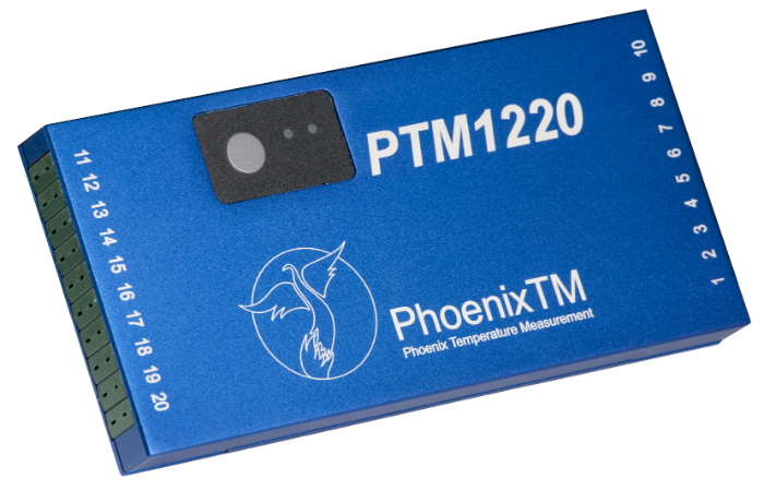
Fig 3: PhoenixTM PTM1220 20 Channel IP67 data logger comes calibrated to UKAS ISO/IEC17025 as an option with an onboard calibration data file allowing direct data logger correction factors to be applied automatically to TUS data.
The data logger shown in Figure 3 has been designed specifically to meet the CQI-9 TUS requirements offering a +/- (0.5°F (0.3°C) accuracy (K & N). Models ranging from 6 to 20 channels can be provided with a variety of noble and base metal thermocouple options (types K, N, R, S, B) to suit measurement temperature and accuracy demands (AMS2750E and CQI-9).
Mixed thermocouple inputs can be provided to support the process specific requirements and also allow the use of the data logger to perform system accuracy testing (SAT) to complement the TUS.
Innovative Thermal Barrier Design
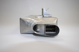
Fig 4: “Octagonal” thermal barrier fitted to product/survey tray.
CQI-9 covers a wide range of thermal heat treatment processes and as such the thermal protection for the data logger will vary significantly. A comprehensive range of thermal barrier solutions can be provided to meet specific process temperature requirements and space limitations. Figure 4 shows a unique octagonal thermal barrier designed to fit within the boundaries of the product tray/survey frame used to perform a TUS using the “plane method” (See “Thermocouple Measurement Positions (TUS)” below in this article.). The design ensures maximum thermal performance within the confines of a restricted product tray/basket.
Live Radio TUS Communication
Fig 5: Schematic of LwMesh 2-way RF Telemetry communication link from data logger TUS measurement back to an external computer.
The data logger is available with a unique 2-way wireless RF system option allowing live monitoring of temperatures as the system travels through the furnace. Analysis of process data at each TUS level can be done live allowing full efficient control of the TUS process. Furthermore, if necessary, by using the RF system, it is possible to communicate with the logger installed in the barrier to reset/download at any point pre-, during, and post-TUS. In many processes, there will be locations where it is physically impossible to transmit a strong RF signal. With conventional systems, this results in process data gaps. For the system shown in Figure 2, this is prevented using a unique fully automatic “catch up” feature.
Any data that is missed will be sent when the RF signal is re-established, guaranteeing 100% data transfer.
Thermocouple Options (TUS)
In accordance with the CQI-9 standard (Tables 3.1.3 / 3.1.5), thermocouples supplied with the data logger, whether expendable or nonexpendable, meet the specification requirements of accuracy +/-2.0°F (+/-1.1°C) or 0.4%. Calibration certificates can be offered to allow the creation of thermocouple correction factor files to be generated and automatically applied to the TUS data within the PhoenixTM Thermal View Survey Software. Care must be taken by the operator to ensure that usage of thermocouples complies with the recommended TUS life expectancies and repeat calibration frequencies. Before first use, thermocouples must be calibrated with a working temperature range interval not greater than 250°F (150°C). Replacement or recalibration of noble metal (B, R or S) thermocouples is required every 2 years. For non-expendable base metal (K, N, J, E), thermocouples replacement should be after 180 uses <1796°F (980°C) or 90 uses >1796°F (980°C). For expendable base metal (K, N, J, E), thermocouples replacement should be after 15 uses <1796°F (980°C) or 1 use >1796°F (980°C). Note that base metal thermocouples should not be recalibrated.
Thermocouple Measurement Positions (TUS)
To perform the TUS survey, a TUS frame needs to be constructed to locate the thermocouples over the standard work zone to match the form of the furnace. The TUS may be performed in either an empty furnace in which case thermocouples should be securely fixed as shown in Figure 6. A heat sink (thermal mass fixed to thermocouple tip) can be used to create a thermal load to match the normal product heating characteristics. Alternatively, the thermocouples should be buried in the load/filled product basket. See Figure 6 to see schematics of TUS Frames for a box and cylindrical batch furnace with CQI-9-quoted number of thermocouples required to match void volume (Volumetric Method Table 3.4.1).
Fig 6: TUS Thermocouple Test Rigs. Required number of thermocouples: 1) Work Volume < 0.1 m³ (3 ft³) = 5; 2) Work Volume 0.1 to 8.5 m³ (3 to 300 ft³) = 9; 3) Work Volume > 8.5 m³ one thermocouple for every 3 m³ (105 ft³). (Click on the images for larger display.)
Fig. 7.1, 7.2. PhoenixTM system showing 9 Point TUS survey rig and Thermal View Software TUS frame library file showing as part of TUS report exactly where thermocouples are positioned. (Click on the images for larger display.)
For continuous conveyorized furnaces, it is recommended that an alternative thermocouple test rig is employed called the “plane method”. Since the system travels through the furnace it is only necessary to monitor the temperature uniformity over a 2-dimensional plane/slice of the furnace (Figure 8). The required number and location of thermocouples are shown in Table 1 (CQI-9 Table 3.4.2).
(Click on the images for larger display.)
Table 1: Required thermocouples and locations for differing work zones (Plane Method)
(1) 2 Thermocouples within 50 mm work zone corners 1 Thermocouple center. (2) 4 Thermocouples within 50 mm work zone corners. Rest symmetrically distributed.
“Thru-Process” Temperature Uniformity Survey (TUS) Data Analysis and Reporting
Operating the PhoenixTM System with RF Telemetry, TUS data is transferred from the furnace directly back to the monitoring PC where, at each survey level, temperature stabilization and temperature overshoot can be monitored live, with thermocouple and logger correction factors applied. The Thermal View Survey software generates TUS reports which comply with the requirements of AMS2750E/CQI-9 standards.
As defined in CQI-9 (Section 3.4) for furnace with an operating temperature range ≤ 305°F (170°C), one setpoint temperature (TUS level) within the operating temperature range is required. If the operating temperature of the qualified work zone is greater than 305°F (170°C), then the minimum and maximum temperatures of the operating temperatures range shall be tested.
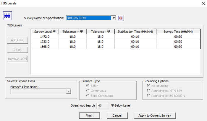
The TUS levels can be automatically set up in the TUS analysis software. Figure 9 shows both the TUS level file and TUS levels applied against the TUS survey trace.
Fig. 9.1Fig. 9.2
Fig 9.1, 9.2 PhoenixTM Thermal View Survey Software showing TUS Level set-up and application to TUS trace.
Within CQI-9, there is a very prescriptive list of what should be contained in the TUS report (Section 3.4.9).
To comply with all said requirements, the software package provides a comprehensive reporting package as shown below.
Fig 10.1, 10.2, 10.3. TUS Report showing a TUS profile at three set survey temperatures (graphical and numerical data). The probe map shows exactly where each thermocouple is located and easy trace identification. A detailed TUS report is generated, meeting full CQI-9 reporting requirements. (Click on the images for larger display.)
Overview
The PhoenixTM Thru-Process TUS System provides a versatile solution for performing product temperature profiling and furnace surveying in industrial heat treatment meeting all TUS requirements of CQI-9 within the automotive manufacturing industry, providing the means to understand, control, optimize and certify the heat treat process.
Alessandro Fiorese, R&D Chief Engineer with TAV Vacuum Furnaces SPA
Alessandro Fiorese, R&D Chief Engineer with TAV Vacuum Furnaces SPA, introduces the vacuum brazing process for automotive applications. For more articles, tips, and news related to heat treatment for automotive applications, keep an eye out for Heat Treat Today’s special print/digital issue Automotive Heat Treating, due in June 2019.
Introduction
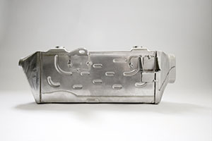
Brazing is a heat treatment process in which metallic parts are joined together through a metallic filler with a melting temperature lower than the melting point of the joined parts. The filler metal can be used as a wire, a thin plate, or a paste depending upon the final application we are considering.
To obtain a good welding in terms of mechanical properties and corrosion resistance, it’s necessary to minimize contamination and impurities in the joined zone. Vacuum brazing processing provides a way to reach a high cleaning level of atmosphere during the brazing heat treatment.
The brazing treatment is particularly useful to produce complex shape parts with a lot of joining points per unit of area. Typical brazing applications are oil or water heat exchangers in the civil and automotive fields such as the ones represented below.
The high-performance aluminum heat exchangers manufacturing is growing particularly in the automotive field. In this context, AA 3xxx and 4xxx are commonly used materials for parts and filler material respectively because these materials have a very low specific weight and a very high thermal conductivity level.
As indicated before, one of the cleanest brazing atmospheres is vacuum. For this reason, in the following discussion, we will analyze in detail the complete characteristics of a semi-automatic TAV vacuum brazing furnace for automotive applications.
Vacuum Brazing Furnace
The entire furnace is composed of three different stations:
the heating furnace;
the loading station;
the cooling station.
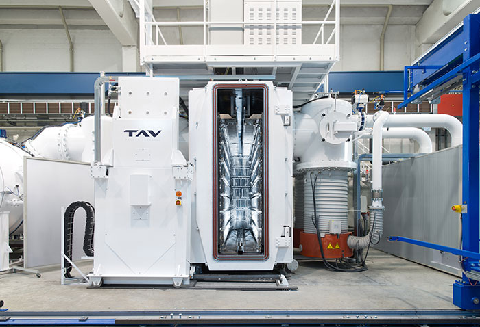
Heating Furnace
heating furnace
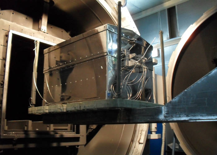
Furnace Vessel
The vessel separates the inner part of the furnace where the hot chamber is placed from the outside environment. The vessel develops along a horizontal axis, it has an elliptical design and it is provided with two flat doors (front and rear). Both doors are hinged and can be opened manually. The front door has an automatically sliding entrance for loading-unloading the furnace.
Hot Chamber
The thermal chamber has a rectangular section 71 (H) x 18 (W) x 144 (L) inches (180 x 45x 365 cm), and it is constituted by steel panels with nickel-chrome resistors. There are 23 independent hot zones that make the chamber temperature very well-controlled. The temperature uniformity requested for this vacuum furnace is ± 37°F (± 3°C) from the set temperature. In the following picture, the ± 37°F Temperature Uniformity Survey (TUS) chart is shown.
Figure 1. TUS example at a specific temperature with 12 TLC
Vacuum System
The vacuum system has three pumping groups, two with a rotary piston pump, a roots pump, and an oil diffusion pump. The third pumping group has a mechanical pump, a roots pump, and a cryo-trap in order to condensate humidity and impurities released during the entire process. The ultimate reachable vacuum without the load is 10-6 mbar (range).
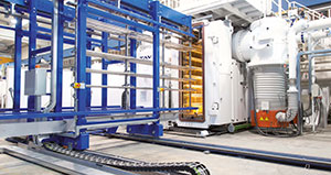
Loading Station
loading station
Loading Baskets
To carry out the brazing heat treatment in a correct way, a specific steel shelved fixtures hold the heat exchangers parts all together with the filler material. For each brazing process, a load from 1984 up to 4850lbs (900 up to 2200kg) can be heat treated at the same time. For gaining a semi-automatic heat treatment process, there is a parking station that can be used as a buffer for the heating furnace.
cooling station
Cooling Station
At the end of the brazing heat treatment, the load is automatically transferred into a separate cooling chamber where the brazed parts are cooled down by forced recirculation of air.
Heat Treatment
Before reaching the brazing temperature, the load is maintained at a lower temperature for a period of time to remove the working oil plate from the heat exchangers. During this maintenance time, a variation between high vacuum and partial pressure of N2 is observed.
Figure 2. Typical brazing cycle. Line yellow is the setpoint, line orange is the temperature TC, line blue is the high vacuum level and purple line is the partial pressure in mbar detected.
After the brazing step, the furnace reaches high nitrogen static partial pressure, starting the cooling phase. This step is considered complete when the furnace injects air up to reach the atmospheric pressure as total pressure. At this time, the front door opens automatically, and the loading track extracts the charge from the furnace.
A major steel manufacturer recently acquired certain assets from a carbon steel tubing provider that supplies induction heat-treated tubes for automotive applications.
Nucor Corp acquired the assets from Century Tube LLC, based in Madison, Indiana, which supplies carbon steel tubing for automotive and other mechanical and structural applications. The company offers round, square, rectangular, oval and other special welded shapes of mechanical steel tubing, and is a leader in supplying induction heat-treated tubes for automotive applications. Since 1993, Century Tube has produced more than 300 million door impact beams for use in Toyota, Honda, Ford, FCA, Subaru, Nissan, and Mitsubishi vehicles.
A leading producer a state-of-the-art aluminum extrusion and forging grade billet and rolling ingot slabs with four plants in North America recently entered into an agreement with a thermal equipment supplier based in St. Louis, Missouri, for the supply of several furnaces in support of the company’s greenfield expansion in Wisconsin Rapids, Wisconsin.
Robert Roscetti, Vice-President of Corporate Development, Matalco Inc. / Photo credit: Light Metal Age
Matalco Inc., which has facilities in Canton, Ohio; Lordstown, Ohio; Bluffton, Indiana; and Brampton, Ontario, ordered from Gillespie & Powers Inc. one 115,000 lb tilting melting furnace, one 115,000 lb tilting holding furnace, three 120,000 lb batch homogenizing ovens, and two 120,000 lb. batch coolers with charging car, and related equipment.
“We are excited about our new partnership with Gillespie & Powers Inc. for the complete furnace equipment installation and commissioning for our new Wisconsin Rapids plant,” said Robert Roscetti, Vice-President of Corporate Development, Matalco Inc. “It represents a major step forward in the construction of Matalco’s new facility, which is on schedule for first production in 2020.”
Main image credit/caption: Light Metal Age / The furnace pictured is a tilting melter in the up position of the type that will be delivered to Matalco Wisconsin.
A leading global aluminum rolling company recently announced it has developed the first aluminum sheet battery enclosure for the rapidly growing electric vehicle and battery sectors.
Pierre Labat, Vice President, Global Automotive, Novelis Inc.
Novelis, Inc., introduced the enclosure which is built with Novelis Advanz™ aluminum products and is up to 50 percent lighter than an equivalent steel design, providing a more sustainable mobility solution in battery electric vehicles. As a result, it matches the best energy density in the industry by enabling more than 160 watt-hours per kilogram, an extremely efficient design for OEMs and Tier 1 battery pack manufacturers. It also can accommodate all battery cell types and is designed particularly for battery electric vehicles with larger power packs such as pick-up trucks, sport utility vehicles, and crossovers.
By utilizing Novelis’ highly-formable alloys, the battery enclosure provides automakers the ability to achieve deep drawn, complex shapes tailored to specific vehicle design requirements. The lightweight, high-strength material can help extend range, allowing vehicles to go 6-10 percent further on a single charge.
“This is the first project resulting from Novelis’ recently launched Customer Solution Center network, which brings research and technical platforms, operations and commercial development together to increase collaboration and innovation with our partners,” said Pierre Labat, Vice President, Global Automotive, Novelis Inc. “With our investment in design, joining and crash management capabilities, we were able to create a stronger, more efficient, and more cost-effective enclosure that can be fully customized to meet our customers’ needs.”
A major U.S. steel producer recently commissioned an international engineering group with the expansion of its steel plant in Osceola, Arkansas, including the supply of electric arc furnaces and other furnace lines, increasing the plant’s annual output to about 3 million tons of steel.
David Stickler, CEO, Big River Steel
Since commissioning of the new mill in 2017, Big River Steel has been producing high-quality steels, including tube grade sheet for pipeline construction, silicon steels for a wide variety of energy and electric motor applications, and advanced high-strength steels for the U.S. automotive industry.
SMS group will supply BRS with mechanical equipment, electrical and automation systems, and digitalization. After completion of the next expansion, the steel plant will have two electric arc furnaces and two twin-ladle furnaces. Installation of an additional gas cleaning system will ensure compliance with strict environmental legislation. A second strand, a second tunnel furnace, and a further downcoiler will be added to the CSP® plant. Big River Steel’s CSP® plant produces up to 1,930 millimeters wide coils, making it one of the widest CSP® plants in the world. Also as part of this project, the continuous galvanizing line (CGL) will receive an additional coiler.
Also in the second construction stage, Big River Steel will see the installation of the PQA® (Product Quality Analyzer) system developed by SMS group company MET/Con as a central module of the process automation system.
Burkhard Dahmen, Chairman of the Managing Board of SMS group
“I have purchased several technologically advanced steel production facilities from SMS over the past twenty years and I am fully confident that SMS group will again deliver a high-quality mill that sets the standard in terms of product capability, energy efficiency and environmental sustainability,” said David Stickler, CEO of Big River Steel.
“Working closely with the management and staff of Big River Steel, we have succeeded in digitalizing a highly complex steel plant in a way that meets the targets of stable and resource-saving production,” said Burkhard Dahmen, Chairman of the Managing Board of SMS group. “We are very pleased about Big River Steel’s decision to also award us the order for the next expansion stage of the steel plant and to continue on the proven successful way with SMS group as their partner.”
Dr. Steve Offley (“Dr. O”), Product Marketing Manager PhoenixTM
This is the final installment in a 4-part series by Dr. Steve Offley (“Dr. O”) on the technical challenges of monitoring low-pressure carburizing (LPC) furnaces. The previous articles explained the LPC process and explored general monitoring needs and challenges (part 1), the use of data loggers in thru-process temperature monitoring (part 2), and the thermal design challenge (part 3). In this segment, Dr. O discusses AMS2750E and CQI-9 Temperature Uniformity Surveys. You can find Part 1 here,Part 2 here, and Part 3 here.
A significant challenge for many heat treaters is the need to provide products certified to either AMS27150 (aerospace) or CQI-9 (automotive). To achieve this accreditation, furnace Temperature Uniformity Surveys (TUS) must be performed at regular intervals to prove that the furnace set-point temperatures are both accurate and stable over the working volume of the furnace. Historically, the furnace survey has been performed with great difficulty trailing thermocouples into the heat zone. Although it’s possible in a batch process when considering a semi-batch or continuous process, this is a significant technical challenge with considerable compromises as summarized below.
Trailing Thermocouple TUS Process Steps
Figure 1. Typical TUS thermocouple. Positions — 9 point survey. Furnace void corners and center
TUS is often carried out using long or ‘trailing’ thermocouples that exit through the furnace door.
Furnace often needs to be cooled, then de-gassed so TUS frame can be set up in the furnace.
Thermocouples are then led out through the furnace door and connected to a data logger or chart recorder.
The furnace is then heated to surveying temperatures.
The survey is then carried out, after which furnace is cooled, and thermocouples are removed.
Disadvantages of Traditional TUS Process
Lots of furnace downtime may be involved (can be up to 24 hours).
Thermocouples have to exit the furnace door.
This may involve “wedging” the door up, or “grooving” out the hearth to get thermocouples out.
Or thermocouples may get caught in the furnace door.
A significant amount of the technician’s time is taken up preparing report.
Applying the “Thru-Process” approach to TUS, the measurement system is transferred into the furnace with the survey frame allowing the setup process to be done quickly, safely, and repeatable. (See Figure 2)
Figure 2. PhoenixTM System loaded into a furnace as part of a TUS frame. Thermocouples pre-fitted to the 8 vertices of the cube frame and center. Furnace ambient temperature recorded either with a virgin exposed junction thermocouple (typical MI) or with heat sink damper fitted.
Operating the system with RF telemetry, TUS data is transferred directly from the furnace back to the monitoring PC where at each survey level temperature stabilization and temperature overshoot can be monitored live with TC and logger correction factors applied. The Thermal View Software is developed to ensure that the final TUS report complies fully to the AMS2750E/CQI-9 standards.
Figure 3. PhoenixTM Thermal View Survey Software showing a TUS profile at three set survey temperatures. The probe map shows exactly where each probe is located and easy trace identification. Detailed TUS report generated with efficiency.
Features incorporated into the Thermal View Software to provide full TUS capability include the following:
TUS Level Library – Set-up TUS level templates for quick efficient survey level specification (Survey Temp °F, Tolerance °F, Stabilization, and Survey Times)
TUS Frames Library – Show clearly exact TUS frame construction and probe location using Frame Library Templates – Frame Center and 8 Vertices.
Logger Correction File – Create a logger correction file to compensate TUS readings automatically from the logger’s internal calibration file.
Thermocouple Correction File – Create the thermocouple correction file and use to compensate TUS readings directly.
TUS Result Table & Graph View – For each TUS temperature level, see from the graph or TUS table instantaneously full survey results.
Furnace Class Reporting – Report the specified furnace class at each temperature level.
Overview
The PhoenixTM Temperature Profiling System provides a versatile solution for both performing product temperature profiling and furnace TUS in industrial heat treatment. It is designed specifically for the technical challenges of low-pressure carburizing (LPC) whether implementing either high-pressure gas quench or oil quench methodology, providing the means to Understand, Control, Optimize and Certify the LPC Furnace and guarantee product quality and process operation efficiency and certification.
A manufacturer of aluminum profiles and complex extrusion press products recently purchased a nitrocarburizing system for its new state-of-the-art manufacturing facility in northwestern Romania.
Quebec-based Nitrex delivered and installed the turnkey NX-815 nitrocarburizing system for Swiss corporation Alu Menziken Extrusion AG, incorporating the Nitreg®-C technology for treating aluminum extrusion dies at the greenfield site which produces a range of profile products for aerospace and automotive companies. The process technology adapts to the application requirements to deliver improved performance of extrusion dies.
“With a focus on the environment, Alu Menziken also sought to introduce eco-friendly technologies for all equipment at its greenfield facility. Not only is there a benefit of reduced process gas use with the Nitrex system, the integral high-efficiency neutralizer also helps comply with environmental regulations,” said Marcin Stoklosa, Nitrex European Project Manager.
A major automaker recently announced that it will base its manufacturing of electric vehicles in Chattanooga, Tennesee.
Volkswagen AG, headquartered in Wolfsburg, Germany, will invest $800 million into the facility, which will be the company’s North American base for manufacturing electric vehicles.
Chattanooga will be the first dedicated location in North America for production of a vehicle using Volkswagen’s modular electric toolkit chassis, or MEB. In addition to Chattanooga, Volkswagen is building the first dedicated EV production facility in Zwickau, Germany, starting MEB production by the end of 2019. Volkswagen will also add EV-production at facilities in Anting and Foshan, in China, in 2020, and in the German cities of Emden and Hanover by 2022.
"The US is one of the most important locations for us and producing electric cars in Chattanooga is a key part of our growth strategy in North America," said Dr. Herbert Diess, CEO of Volkswagen AG.
Volkswagen of America will offer the first EV based on the MEB platform to customers in 2020. This vehicle will be a series-production version of the ID. CROZZ SUV concept, first shown at the North American International Auto Show last year. This vehicle will have the interior space of a midsize SUV in the footprint of a compact SUV. Volkswagen of America will also offer a multi-purpose EV based on the ID. BUZZ concept.
Volkswagen currently builds the midsize Atlas SUV and the Passat sedan at the Chattanooga factory, which opened in 2011. A five-seat version of the Atlas, the Atlas Cross Sport, will begin production in Chattanooga later this year.
Scott Keogh, CEO and president of Volkswagen Group of America
"We could not be prouder to build the future of mobility here in the U.S.," said Scott Keogh, CEO and president of Volkswagen Group of America. "We’re known as ‘the people’s car' for a reason, and our EVs will build on that tradition."
Globally, Volkswagen Group plans to commit almost $50 billion (44 billion euros) through 2023 toward the development and production of electric vehicles and digital services.