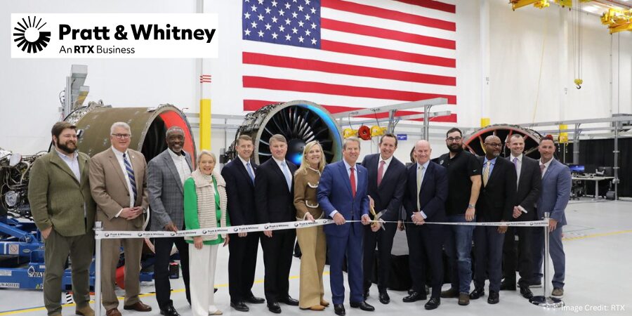
Pratt & Whitney, an RTX business, is investing $200 million to expand manufacturing at its Columbus, Georgia, site with the addition of a seventh isothermal forging press. The equipment, which will support production of rotating compressor and turbine disks for commercial and military jet engines, is expected to be operational in 2028 and is projected to increase output of these critical components by about 30 percent.
The funding will expand operations at the Columbus Forge facility, where compressor airfoils and high-strength disk components are manufactured for the company’s commercial and military engine platforms. The site is part of the broader Columbus campus that also includes the Columbus Engine Center, where maintenance, repair, and overhaul (MRO) work is performed on engines like the PW1100G-JM, V2500, PW2000, F117, and F100.
Shane Eddy President Pratt & Whitney
The latest investment at the Columbus Forge facility follows an 81,000-square-foot GTF MRO expansion at Pratt & Whitney’s Columbus Engine Center, located on the same campus. This expansion added advanced equipment and machinery that aligned with the company’s Industry 4.0 strategy. The facility’s annual capacity increased by more than 25%, adding critical overhaul volume to the GTF MRO network in support of the growing fleet.
The Columbus complex has grown from a small manufacturing facility to a manufacturing and overhaul center that now employs 2,600 people. “Since 2008, we have invested more than $1 billion to continue expanding the footprint and capabilities of our Columbus facility. This latest investment will increase output of critical parts for our growing military and commercial engine programs and underscores our ongoing commitment to ramp industrial capacity to support our [clients],” said Shane Eddy, president of Pratt & Whitney.
Press release is available in its original form here. Main image shows Pratt & Whitney President Shane Eddy joined with Georgia Governor Brian Kemp and other company, state, and local leaders to celebrate two major expansions of Pratt & Whitney’s Columbus, Georgia facility on February 24, 2026.
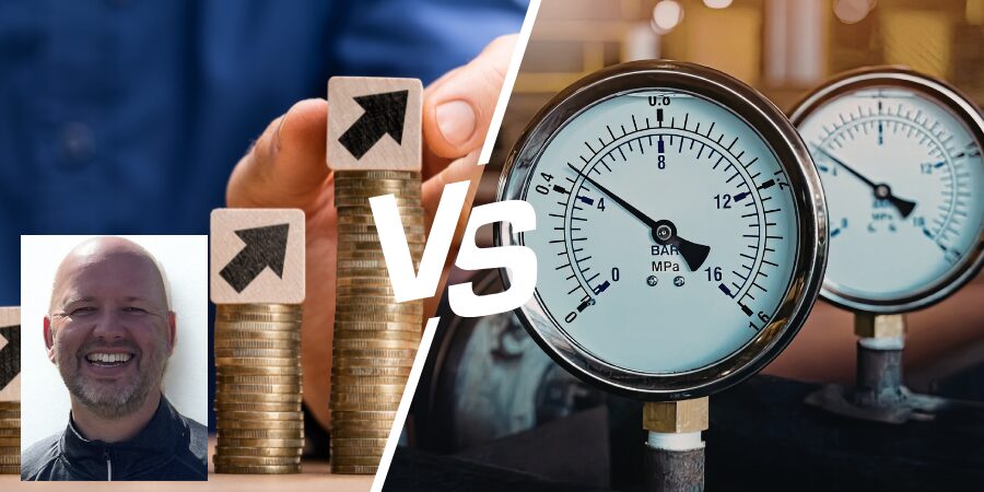
What’s the real price of a leak test system? According to Norbert Palenstijn of Nolek, it’s not the number on the invoice. In this guest column, he walks through why total cost of ownership — spanning calibration, consumables, throughput, and quality impact — should drive purchasing decisions more than CapEx alone.
When a factory considers new capital equipment, the first question almost always sounds the same: “What’s the CapEx?”
It is an understandable starting point. Capital expenditure is big, visible, and easy to compare. Numbers sit neatly in a column, budgets are allocated, and decisions get made. But if we stop there, especially when it comes to leak testing equipment, we risk seeing only half the picture.
Leak testing has one main role in production: it is a sorting function. Its job is to distinguish between good and bad parts based on a leak specification. That means it is not just a machine — it is the gatekeeper of quality. And for a gatekeeper, what matters most is not just the cost of admission, but how reliably the gate opens and closes.
The Hidden Cost of “Lower Purchase Price”
Imagine two leak test systems on the factory floor. One has a lower CapEx and looks attractive on paper. But in practice, it requires more frequent calibrations, eats through consumables, and delivers an uncomfortable number of false rejects. Every false reject creates rework and lost time. Every misclassified “pass” creates a risk that defective parts slip through. Suddenly, the lower cost option does not feel so appealing anymore.
Now compare it to a system with a higher upfront price but stable measurement performance, longer service intervals, and better correlation to the specification. Over years of production, this system quietly saves money and protects reputation, even if the original CapEx line was higher.
Beyond the Purchase Price
Image Credit: @TarikVision/AdobeStock
Focusing only on CapEx is like buying a sailboat and budgeting for the hull, but forgetting sails, navigation equipment, and upkeep. The hull might look affordable, but the true cost of ownership is what keeps the ship sailing safely across oceans.
In leak testing, the total cost of ownership (TCO) includes:
Purchase and installation (CapEx)
Calibration, service, and downtime (OpEx)
Consumables and spare parts
Impact on throughput (cycle times, operator time)
Impact on quality (false rejects and escapes)
These factors flow directly into cash flow, customer satisfaction, and brand reputation.
The Real Measure of Value
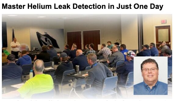
Learn the fundamentals of helium leak detection firsthand at Heat TreatToday’s Leak Detection Seminars. Click the image above to register for a session near you.
Leak test systems do not just live on balance sheets, they live in production lines. Their value is measured not just in cost, but in confidence:
Confidence that every part has been tested against specification
Confidence that defects are caught before they leave the factory
Confidence that customers can trust what you ship
That’s why a decision made only on CapEx is incomplete. A leak test system is a long-term partner in your production process. It is not just a one-time payment, it is what you pay and gain every day it runs.
Closing Thoughts
When considering new leak testing equipment, do not just ask, “What is the CapEx?” Ask instead:
What will it cost me to run?
What will it cost me if it fails to sort correctly?
What confidence does it provide in every product leaving my site?
Because in the end, the true price of a leak test system is not the invoice you pay at purchase. It is the trust it secures, or fails to secure, for years to come.
About The Author:
Norbert Palenstijn U.S. Brand Manager Nolek|VES|ALPHR|Natgraph
Norbert Palenstijn has built a career as a recognized specialist in helium and hydrogen leak detection, with over 26 years of dedicated experience in industrial vacuum systems, industrial leak testing and detection, and advanced engineering solutions.
A new downstream aluminum fabrication facility is being planned in Inola, Oklahoma, to convert molten primary aluminum into value-added products. The project is intended to strengthen domestic aluminum supply chains and expand U.S. primary aluminum processing capacity by anchoring fabrication operations adjacent to a proposed new smelter.
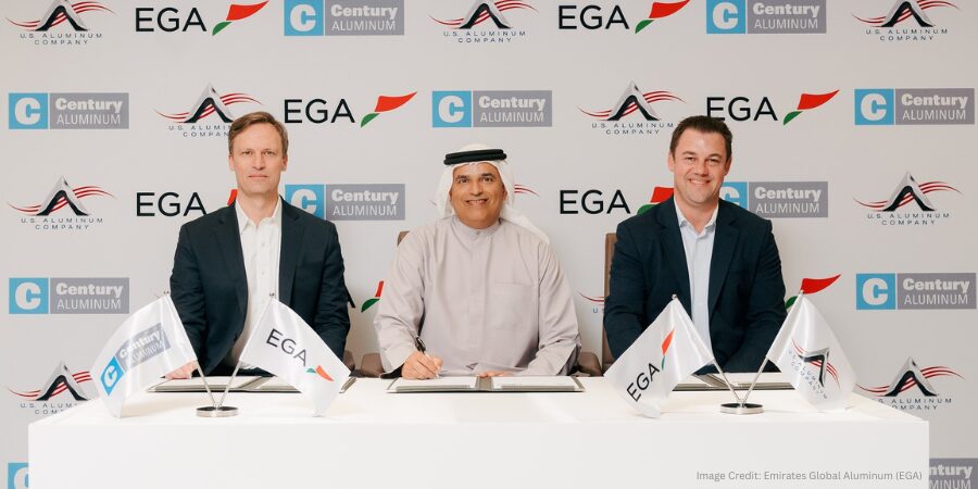
Local firm U.S. Aluminum Company has signed an agreement with Emirates Global Aluminum (EGA) and Century Aluminum, the companies behind the planned primary aluminum production plant in Inola, Oklahoma, to explore the development of an aluminum fabrication plant near the smelter. The project, named Oklahoma Primary Aluminum, is expected to double U.S. primary aluminum production. U.S. Aluminum Company is the first downstream firm to formalize an agreement tied to the project.
Jesse Gary CEO Century Aluminum
U.S. Aluminum Company plans to build its facility near the smelter to process liquid aluminum into products for the electrical, defense, aerospace, automotive, and machinery industries. By locating next to the smelter, the company aims to strengthen the domestic supply chain and support growth of a broader downstream manufacturing ecosystem in the region.
“By establishing an aluminum hub in Oklahoma, we are strengthening and shortening the supply chain for a critical metal that supports American industries. Today’s announcement highlights the multiplier effect of revitalizing domestic production — attracting new infrastructure investment and creating jobs in adjacent industries,” said Jesse Gary, chief executive officer of Century Aluminum.
Founded by the Oklahoma City-based Plotkin family, owners of M-D Building Products, a long-standing aluminum fabrication company, U.S. Aluminum Company is focused on serving clients requiring domestically produced aluminum with high performance, traceability, and supply security.
Press release is available in its original form here.
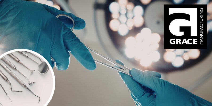
Grace Manufacturing is expanding its vacuum heat treating capabilities to support growing demand for thin martensitic stainless steel components used in the medical industry. The Arkansas-based precision metal manufacturer has invested in a new vacuum furnace to strengthen process control, reduce downtime, and maintain stringent metallurgical and quality standards required for medical component production.
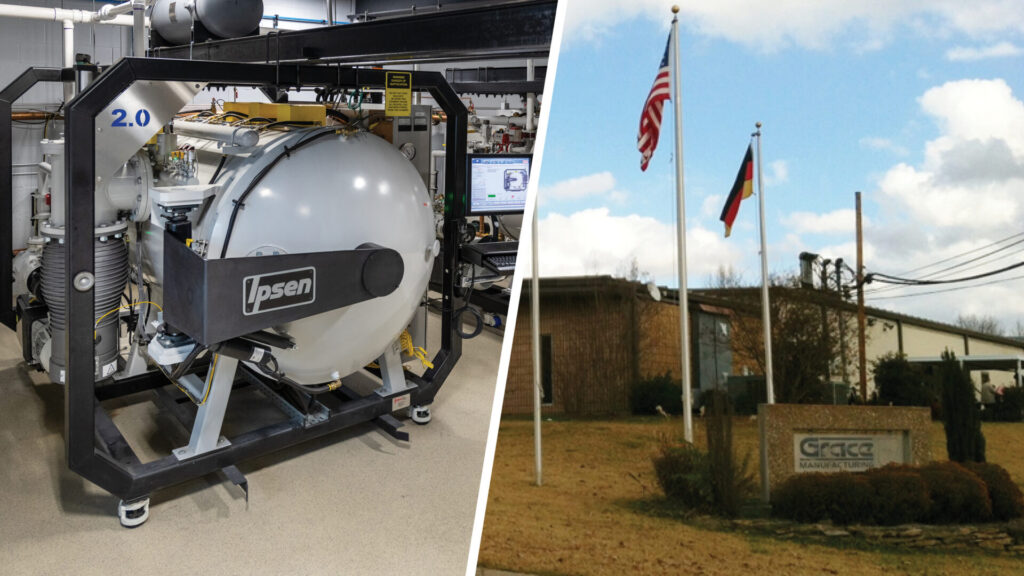
Located in Russellville, Arkansas, Grace Manufacturing selected a TITAN H2 2-bar vacuum furnace following third-party testing at a Midwest commercial heat treater. The evaluation confirmed the system met application requirements for thin martensitic stainless steel medical components. The new furnace will replace an aging unit from another manufacturer that has experienced increasing downtime and service challenges in recent years.
Image Credit: Ipsen
Supplied by Ipsen, the TITAN H2 includes a work zone measuring 18 x 18 x 24 inches deep, a 1,000-pound load capacity, and a maximum operating temperature of 2400°F. The system provides temperature uniformity of ±10°F, supporting the repeatability and precision required in medical manufacturing environments.
Established in 1966, Grace Manufacturing specializes in precision metal services primarily serving the medical industry. The upgrade in equipment supports Grace Manufacturing’s continued growth in medical component production.
Press release is available in its original form here.
JISCO Carbon Steel, a global steel producer serving international markets including North America, has commissioned a new integrated CSP®-HSM line at its Jiayuguan facility following an upgrade and expansion project. The new production line combines Compact Strip Production (CSP®) with a hot strip mill (HSM) into a fully integrated system with complete automation. The move increases annual production capacity from 2 million to 4.5 million tons and enhances operational flexibility and stable production performance.
The newly commissioned line integrates CSP® casting and rolling with a newly installed hot strip mill, creating a continuous production route that allows rapid switching between production modes. According to the company, the system enables fast ramp-up and stable rolling performance while maintaining controllable quality from the start of operations. Importantly, the expansion was executed without interrupting ongoing CSP® production.
The upgrade includes the installation of new mechanical equipment and a complete automation package designed to coordinate casting and rolling operations. The automation system supports process control, operational stability, and consistent production results across product grades.
Technology and automation systems for the integrated CSP®-HSM line were supplied by SMS Group, which provided engineering, mechanical equipment, and its X-Pact® automation platform, including models and visualization systems for coordinated line control.
Commissioning ceremony on February 2, 2026, at JISCO’s site. | Image Credit: SMS Group
“Bringing the world’s first integrated CSP®-HSM line into production is a strategic leap for JISCO Carbon Steel. We now have the flexibility to align products and processes with customer needs in real time, backed by stable, repeatable quality from day one,” said Mr. Qiao Degao, CEO of JISCO Hongyu New Materials Co., Ltd. “SMS group’s automation technology and disciplined project execution were essential to meeting our schedule and performance targets.”
With the line now in operation, JISCO expands its production capacity and strengthens process integration between casting and hot rolling, positioning the Jiayuguan facility for increased throughput and operational flexibility in the flat steel market.
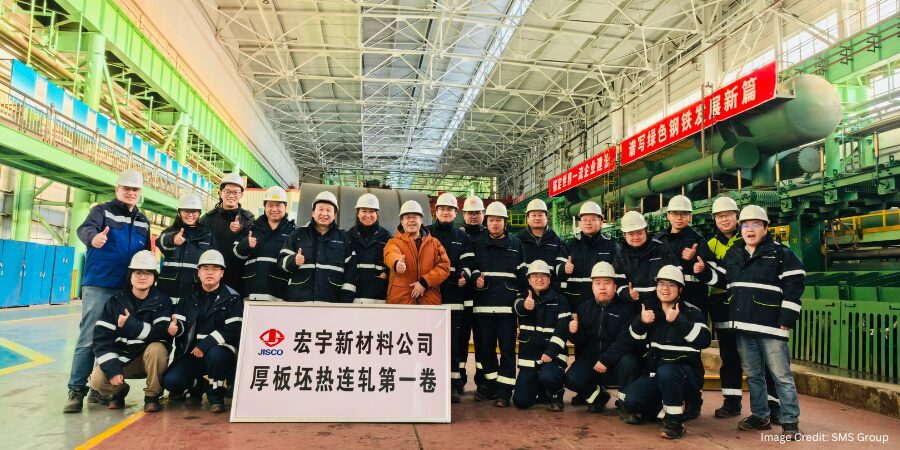
Press release is available in its original form here. Main image shows the SMS Group team at JISCO after the successful first coil. Image Credit: SMS Group
Heat TreatRadio host Heather Falcone is joined by Andrew Bassett, president of Aerospace Testing and Pyrometry, for a deep dive into AMS2750 and best practices for managing pyrometry compliance. Drawing on more than 35 years of hands-on experience and his role on the AMS2750 writing team, Bassett explains how the specification has evolved and why pyrometry continues to drive a majority of audit findings. The conversation explores common compliance pitfalls, practical system-level solutions, and how heat treaters can better prepare for audits without over testing. Falcone and Bassett also discuss the value of industry involvement in shaping standards that directly impact daily heat treating operations.
Below, you can watch the video, listen to the podcast by clicking on the audio play button, or read an edited transcript.
The following transcript has been edited for your reading enjoyment.
Introduction (00:04)
Heather Falcone: Hi, I’m Heather Falcone, and welcome to Heat TreatRadio. Today we are talking about AMS2750, and the best practice to manage pyrometry compliance. Joining me today is Andrew Bassett, president of Aerospace Testing and Pyrometry. Andrew has more than 35 years of experience working alongside manufacturers, captives, and commercial heat treaters to ensure their testing calibration and pyrometry programs meet the demands of industry specifications like AMS2750 without losing sight of how shops actually operate.
Aerospace Testing and Pyrometry (ATP) provides accredited testing, calibration, and pyrometry services nationwide that support heat treaters and aerospace manufacturers across compliance, audit readiness, and ongoing system integrity. The company also developed the Aerospace Compliance System (ACS), a software platform designed to support compliance and documentation requirements tied to testing and pyrometry programs.
Andrew is deeply involved in the aerospace, metals, and engineering committee responsible for writing AMS2750 specification and is an active contributor within the Nadcap Heat Treat Task Group. He brings practical systems level views of quality that go beyond checklists and audits.
Tell us a little bit about yourself, other than my delightful intro. There’s more about you, your industry involvement, and about ATP.
Andrew Bassett: I’ve been involved with pyrometry for 35 years now. My involvement with pyrometry started with a family-owned business. About the time when the Nadcap process was coming to fruition, some of my mentors, who are still my mentors today, dragged me to my first Nadcap meeting and said, “Well, if you’re going to do this pyrometry stuff, then you better learn it.”
Off I went to Hartford, Connecticut for my first understanding of Nadcap and how much pyrometry is a big part of the thermal processing industry. From that point forward, I dove into the specifications and wanted to be a part of a solution rather than contributing to the problem.
I got involved with AMS2750 and AMEC. When I showed up to my first meeting, the chairman at the time wanted to know who I was and what I was doing there. After explaining what I do and my desire to join the 2750 team, he said absolutely, because at that point, I was the only person in the sub-team that had hands-on experience in pyrometry and was writing the standard. I’m the one that actually picks up the thermocouple, sticks it inside a furnace, and knows what the real world is. Thankfully the chairman saw that and said, “You need to be a part of this.”
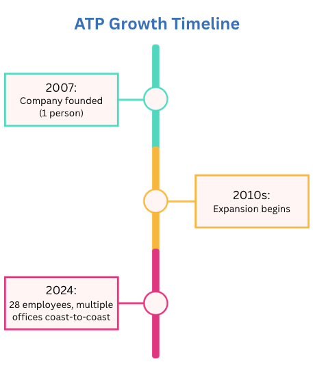
I started Aerospace Testing and Pyrometry (ATP) in 2007. When I first started the company, I wanted to dedicate my focus on helping our clients succeed, and make sure that we are the industry experts, providing the customer service that they deserve. I wanted to look at what the specification allows for frequency reductions and stop over testing the equipment, while staying within the compliance requirements of the standards.
AMS2750 is not the only pyrometry specification out there. We then got involved with the other aerospace prime specifications, ensuring our customers maintained compliance to those as well.
We have branched out since those early days of 2007, which consisted of me running around the country, taking care of pyrometry. Now we have 28 people in the business and multiple offices coast to coast with a great team behind us that shares the same vision, ensuring pyrometry service is our ultimate focus for our clients.
Heather Falcone: What is really important about that is that, as a former heat treater actively helping the heat treat industry now, there is not one system that puts all of these standards and specifications together. Companies have their records, data collection, and everything is all separate.
What is ACS? (5:37)
Heather Falcone: Tell us a little bit about ACS and how this software helps with this issue.
Andrew Bassett: The dream of the aerospace compliance software came out of us doing things the old-fashioned way, entering calibration data into an Excel spreadsheet, which enables the human factor and leads to human errors. When it comes to compliance audits, human errors cannot happen. So we tightened up our processes in the Excel world, but I knew there had to be a better way.
That is how we started down the road of developing aerospace compliance software. The idea was that it was going to be strictly an ATP tool to use for my technicians and the team to use the software. But the industry is small enough that people started hearing about what we were doing. Clients began requesting to be able to use the software. That is how the system has grown to where it is today.
Back in my early days in pyrometry when I started ATP, I would literally build pyrometry compliance notebooks, old fashioned binders. When we would get a new client, I would go buy a bunch of notebooks from Staples and put in their little dividers of a pyrometry program together. We would have information and specifications about their furnace, calibration reports, SAT reports, TUS reports, thermocouple control logs, etc. That’s where ACS has now been built, replacing my old notebooks.
Now we have a system that’s 100% not just a pyrometry tool — it’s also a compliance tool. New features we have added have a focus on compliance, just not pyrometry-related tools. We now have tools for preventive maintenance leak rate testing checks that are required and controlling your thermocouple replacement schedule. It’s bigger than a pyrometry tool now.
This software has now expanded across multiple industries, not just in heat treating and thermal processing, but also chemical processing, NDT, composites, etc. It is a fully compliant software for multiple industries.
Heather Falcone: It’s meant to be that holistic, wraparound software for your quality folks to have someplace safe that all their data can get stored, aggregated, and usable.
Andrew Bassett: It’s also and most importantly a self-checking software to not only the industry specifications, but client internal specifications. It doesn’t have to be solely what AMS2750 says. It could be 2750 or GEs requirements, or Boeing’s requirement, or an internal spec. It will parse all that information to make sure it’s compliant to those standards, and it’s completed faster than you can blink your eye.
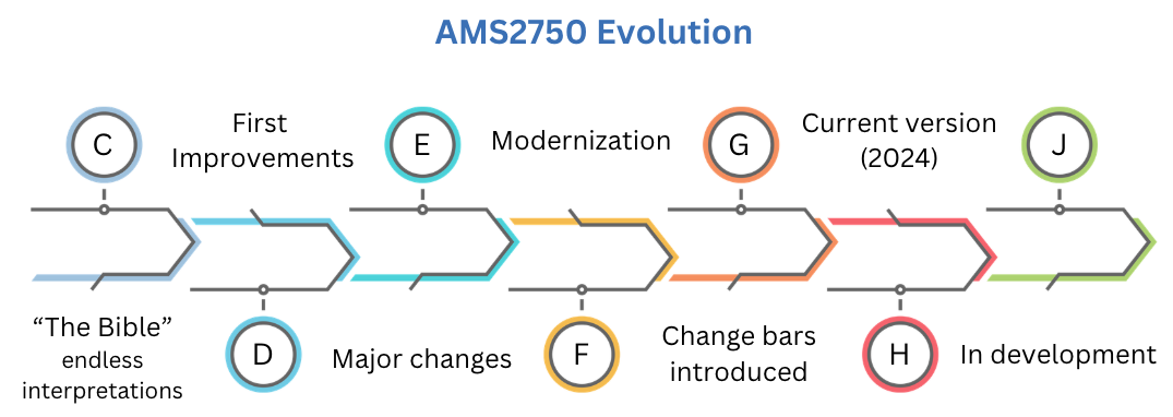
AMS2750 (9:20)
Click the image to get a deep dive into AMS2750F fundamentals, as Andrew breaks down the core requirements of AMS2750F.Click the image to learn about navigating AMS2750F compliance challenges.Click on the image to understand the critical role of Temperature Uniformity Surveys (TUS) in ensuring repeatable heat treating processes under AMS2750F
Heather Falcone: Can you talk about AMS2750, how it has evolved beyond I think what many of us ever thought it would be, and some best practices on how you can best get your arms around that standard and manage that day to day?
Andrew Bassett: When I got into the industry, we were at Rev C, AMS2750C, and those who’ve been around long enough to know that revision of the spec was the Bible. You gave it to a hundred different people and you got a hundred different interpretations.
It was very unclear on the spec. The iterations from there have gotten better, with 2750D and then the major changes going into E, then all the way up to our current state of Rev H. It’s now more clear, though there are still some confusing parts. My goal personally is to make sure that document is clear and understandable. Even if it’s 300 pages and we use stick figures and crayons to explain what the intent is — I’m okay with that. So it shouldn’t be a document that is hard to understand. The aerospace standards for heat treating are fairly clear on the intent of the spec, but for some reason, pyrometry has always been this scary black hole that you have to try to figure it out. I’m looking forward to the day where that is not the case.
Click on the image above to check out Heat Treat Radio #91 where Andrew demystifies one of AMS2750’s most critical yet often misunderstood specs: the ±0.1°F requirement.
Coming to a understanding of that specification is not easy to do. Understanding what the intent and the requirements are takes some good studying, as well as getting the intimate training of that specification.
We do provide pyrometry training, and when I first started doing it, it was a 6- to 8-hour day class, the 30,000-foot level. Over the last several years, I’ve broken it now into a two-day class. My PowerPoint presentation has expanded to 168 slides when the spec is only 57 pages. But now I’m doing more of a crop-dusting training level so everybody can understand it. That is extremely helpful for suppliers that need to meet that standard.
Heather Falcone: Interpretation is key for suppliers, understanding how the standard applies to their shop, their floor — that’s a real challenge.
Andrew Bassett: The specification is just not a North American spec. It’s a global specification, and it’s not even just an aerospace standard anymore. It’s gone into the commercial world, the FDA. Now, if you’re doing heat treatment of dental drill bits or knee replacement parts, anything that’s metal, the FDA now requires compliance to AMS2750. Having someone walk you through the standard and reaching out, there are many ways to figure out the intent of the spec and how it applies to each organization.
Best Practices in Managing the Beast (14:40)
Heather Falcone: What are some best practices in managing this if you have to integrate AS, ISO, Nadcap? You have your whole QMS, and then you have 2750, P10TF3, etc. How do you do it?
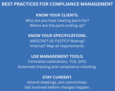
Andrew Bassett: That’s a huge undertaking. My experience over the years is diving in with our clients and finding out what types of heat treating they are doing. I like to find out who they are heat treating parts for, who are the clients, where are the parts ending up? There could be POs coming in for the clients to heat treat “X” part, and maybe they are not doing their due diligence and the part is actually going to GE Aviation. Well, GE Aviation has their own pyrometry requirements that are offset from AMS2750 or Saffron or any of the other aerospace primes that may have a requirements from a pyrometry standpoint.
So first gathering that information altogether and making sure you are constantly up to date of what you’re processing is critical. From there, with the aerospace compliance software, now that tool can be utilized to manage all your requirements, from your calibrations, your TUS, your SATs, everything can be managed in one location.
For instance, if you’re doing work for GE, and you have to follow their requirements of P10TF3. GE does not have anything in their specification that talks about the alternate SAT that’s specified in AMS2750, but GE also do work that needs to comply with that standard. So this tool is going to keep you on track. This kind of management tool is cabale of managing that for you, so nothing gets missed.
Once that knowledge base is put together and we have a clear path of what needs to be done from the heat treater or the captive shops standpoint of who they are processing work for, then you can use something like ACS that can manage that whole aspect for you.
How Does ACS Work with Other Systems? (17:06)
Heather Falcone: From what I understand, ACS is plug and play. It comes on-site, ready to go as a standalone tool. But how does it also work with other systems that you might have?
Andrew Bassett: ACS is a standalone system. People have access to it; we have a tiered subscription for it depending on what level of the ACS you want. We have also been working with a few industry giants out there to integrate ACS software with certain systems that help manage heat treat processes. There will be an integration point there where ACS will be able to make sure that jobs don’t get processed if TUS or calibration or SATs are past due for heat treat equipment. They won’t be able to enter a job into that piece of equipment. It will stop them from putting something that shouldn’t be going into a furnace. These are some of the features that we will be integrating in 2026 where we’ll be able to work with other software solution providers out there in the heat treating realm to make sure everybody is looking at the same thing.
Heather Falcone: The reason that we want those lockouts in place is because we are trying to avoid NCRs during our audits. We’re trying to get NCRs that will be value-add, not something that we knew we should have been doing and were not. The whole point is to better the company so that we do not have a bunch of pyrometry NCRs during our audits.
Common NCRs for Pyrometry (19:08)
Heather Falcone: What are the top NCRs that you’re seeing for pyrometry currently?
Andrew Bassett: It has been well documented through the Nadcap process that 80% of NCRs actually do come from pyrometry. That has always baffled me, especially being a member of AMS2750 sub-team that writes the standard. What have we done as a team to fail the suppliers out there by not writing clear consistency?
Over the last two revisions, I think many requirements have been clarified. But there are still some pyrometry-related issues that I still see. For example, you may have your preventive maintenance or unscheduled maintenance that is being completed to a piece of equipment. You have a requirement to have that maintenance documented and then approved by a by someone from quality to make sure that no further pyrometry testing is required. Sometimes those logs are missed, or possibly a maintenance manager verifies a door seal was replaced, but then quality does not sign off and date that log.
That is an example of an issue that we identified and put into ACS. Now you can keep that preventive maintenance program in ACS for that particular piece of equipment. With unscheduled maintenance, when the maintenance is completed, it automatically shoots an email to the quality team to have them review and ensure no pyrometry requirements are missed.
That’s an example of one of those top NCRs that you always see with Nadcap. We saw the need and created a solution to that with ACS.
Benefits of Getting Involved (21:11)
Heather Falcone: We want to make sure that everybody can get more involved in shaping the face of compliance so that they do not become a victim of it. How can everybody, including captives, get more involved, and why is that valuable to their bottom line?
Andrew Bassett: This is something I preach constantly with our client base. If you’re Nadcap accredited, firstly, go to a meeting. Learn, be present. You have a say. I’ve been going to Nadcap meetings for 30+ years now, and even though I’m not a supplier, I’m not an aerospace prime, I’m a guest that that shows up. But I keep going and I raise my voice and share my concerns with the group at Nadcap and with the suppliers. Having that voice is important. I know that suppliers need to get more involved. I know it’s an expense to send several people from a company out to a Nadcap meeting, but it’s money well spent when you get involved with AMEC and with creating the specifications.
I had this myth early on in my career that this golden group of aerospace gods were creating standards. When I showed up to the meeting, there were more suppliers there writing the standards than there were the primes. It was amazing to see that we have people that are in the industry that do the heat treating or in the metallurgist or for these organizations that are in charge of the specs. It’s the everyday heat treater, the people with boots on the ground, so to speak, that get involved. So getting involved with AMEC, getting involved with Nadcap, that’s key to any success when it comes to compliance and having that say in writing standards that you know what you’re going to have to comply with.
Heather Falcone: Absolutely. They give us so many opportunities to get involved. There’s four AMECs a year and three Nadcap meetings.
Andrew Bassett: To me it’s well worth it. At least go to the Nadcap meeting that’s always once a year in Pittsburgh. It is the most well attended meeting typically out of all of them. That one is really going to get your feet wet and get that whole experience of Nadcap.
Heather Falcone: That’s usually where they’re making major decisions, like finalizing checklist changes. Being able to get out in front of that and not just wait to get the email from the automated PRI.
Andrew Bassett: I will move mountains to make sure that I am at every Nadcap meeting. For us, I can take that information for those meetings for my clients that don’t end up going and be able to disseminate that information. It doesn’t matter if it’s pyrometry or heat treating or whatever that’s coming out and say, this is coming down the pike. Where do we need to tighten some things up?
Developing Compliance Software For Complex Specifications (25:46)
Heather Falcone: Most of the time I’ve seen when I’m going in to see a heat treater that their compliance program is great at a base level, but there’s too many pieces. So what has that been like trying to develop a compliance software for literally one of the most technically complex and arguably important specifications in our industry?
Andrew Bassett: It’s been a challenge for sure. With AMS2750, at one point it was starting to be updated every two years. Thankfully, we have four developers on our software team, so all the developing for us is in-house. Being on the forefront of changes by attending Nadcap meetings and being a part of AMEC, we can jump right into development and be ready for the update.
Future Specifications and Revisions (27:30)
Heather Falcone: We are on Rev H — what’s next? Is there another spec change on the horizon?
Andrew Bassett: Letter J is on the horizon. We did start working on it. Once the spec is released, the team keeps a parking lot of issues that come up. Then we just basically put it on a storyboard, and when we’re ready to start working on them again, we start working on it. The changes over the last two revisions on G and H, have been minor. It was the first time in the history of the specification, back at Rev G, that there were change bars for the first time.
A change bar is on the left-hand side of the document, indicating where we changed something in the spec. Prior to that, we rewrote the spec and people had to read the whole thing to know what had changed.
I don’t see a time where we’re ever going to have a complete overhaul rewrite of the spec in the future. So yes, we are working on Rev J. These updates will be more clarifications that have sprung up over the last several years. We were trying to put one out every two years to keep up to date. The aerospace community, Nadcap, and AMEC, they were getting a little antsy that we were writing it so quickly, so we put a little pause on that.
We did jump back into it a couple weeks ago. We had our team meeting and worked out a few more issues that are out there. Not a big major overhaul, more clarifications and trying to get more intention of what the requirements that we’re writing.
From a Nadcap standpoint, with any changes to industry specifications, there will be updates on new checklist revisions. That’s always a grinding process to get a checklist that everyone’s going to be happy with. I did not yet look at the agenda for the next meeting in February in San Francisco, but it seems like every time we do have a meeting, there’s a checklist that we’re working on.
Heather Falcone: That is a great takeaway — get involved, right? Go to the meetings, take your opportunities, get involved with people like Andrew that have been in the industry. It’s a wealth of knowledge, and if we’re not taking advantage of your expertise, your experience, then we’re really missing out on taking knowledge back to our own shops.
Is there anything that you want to leave us with before we close out?
Andrew Bassett: You’re spot on with that. That’s that actually what brings me the most joy of what I do is being able to part the knowledge that I have to my clients. Anytime I meet somebody and we talk pyrometry, my business card comes out and I have my cell phone number on there. I tell them, go ahead and call me, text me, smoke signals, whatever you want to do. If there’s a question you have, I’m more than happy to answer it to the best of my abilities. I mean, I’m only one of 12 people on the team. It’s about parting that knowledge and assisting our clients to be successful and have a great understanding of what the requirements are and really make sure that they understand it.
About the Guest
Andrew Bassett President Aerospace Testing & Pyrometry
Andrew Bassett has more than 35 years of experience working alongside manufacturers, captives, and commercial heat treaters to ensure their testing, calibration, and pyrometry programs meet the demands of industry specifications like AMS2750 without losing sight of how shops operate. Aerospace Testing and Pyrometry provides accredited testing, calibration, and pyrometry services that support heat treaters and aerospace manufacturers across compliance, audit readiness, and ongoing system integrity. The company also developed the Aerospace Compliance System, a software platform designed to support compliance and documentation requirements tied to testing and pyrometry programs. Andrew is deeply involved in the Aerospace Metals and Engineering Committee responsible for writing the AMS2750 specification and is an active contributor within the Nadcap Heat Treat Task Group. He brings a practical, systems-level view of quality that goes beyond checklists and audits.
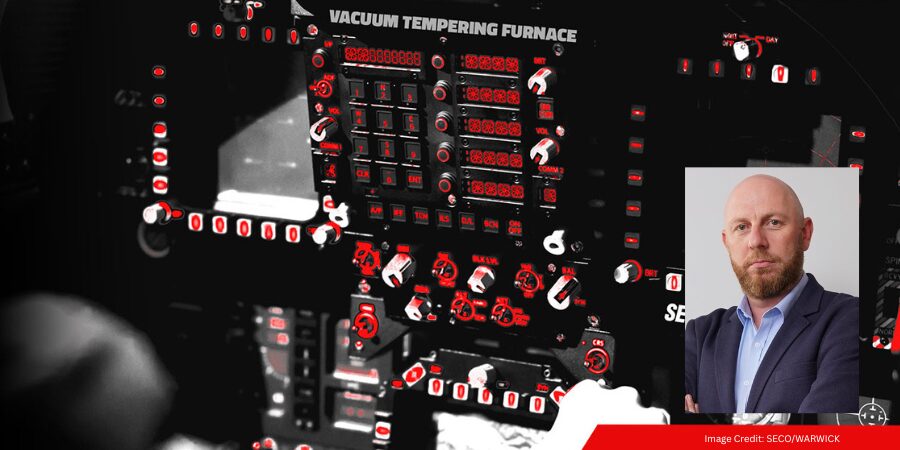
An international aircraft motion-control manufacturer is expanding its heat treat process capacity by ordering an additional low-temperature vacuum tempering furnace to support tempering, aging, and other sub-critical heat treating of precision components. The equipment will be used to maintain consistent thermal processing standards for aerospace applications.
The repeat order will be supplied by SECO/WARWICK‘s U.S. subsidiary. The furnace is a low-temperature vacuum tempering unit capable of operating up to 1380°F (750°C) within a 24 × 24 × 36 in (600 × 600 × 900 mm) work zone and supports a 1750-lb (~800 kg) load capacity. Designed to meet AMS2750F Class 2 temperature-uniformity-survey (TUS) requirements (±10°F/±5.6°C), it uses nitrogen convection for both heating and cooling, with final cooling provided by an internal recirculation blower and water-cooled heat exchanger for stable, efficient cycles.
Piotr Zawistowski Managing Director SECO/WARWICK USA
This additional furnace joins an existing suite of heat treat equipment at the manufacturer’s facilities, which already includes multi-chamber CaseMaster Evolution models and a Vector single-chamber high-pressure gas-quench vacuum furnace from SECO/WARWICK. These installations reflect long-standing collaboration on thermal processing solutions for aerospace components.
According to Piotr Zawistowski, managing director of SECO/WARWICK USA, the ongoing investments by this aerospace partner reflect confidence in the technical expertise and support provided by SECO/WARWICK and the performance consistency of its vacuum tempering solutions.
Press release is available in its original form here.
Ask The Heat Treat Doctor® has returned to bring sage advice to Heat Treat Today readers, answer questions about heat treating, brazing, sintering, and other types of thermal treatments, as well as metallurgy, equipment, and process-related issues. In this installment, Dan Herring examines the devastating effects of hot gaseous corrosion on furnace alloys: exploring the mechanisms behind metal dusting, the gas-solid reactions that drive catastrophic carburization, and the mitigation strategies to extend the life of heat treaters’ most valuable furnace components.
This informative piece was first released in Heat Treat Today’sJanuary 2026 Annual Technologies To Watch print edition.
Have questions or feedback? We’d love to hear from you — reach out to our editorial team at editor@heattreattoday.com.
Corrosion is a concern experienced by everyone involved in manufacturing industrial products. While there is a plethora of data and information on the effects of corrosion on engineered materials available (sources provided in the references section of this column), most corrosion engineers are focused on aqueous corrosion. By contrast, heat treaters must understand the effects of hot gaseous corrosion, especially on our furnace alloys. Let’s learn more.
Corrosion Basics
It is important to understand that all materials are chemically unstable in some environments and corrosive attack will always occur. In the scientific world, it can often be modeled and its effects predicted by studying thermodynamic data and knowing which of the many corrosion-related chemical states are active. In our world, however, it is equally important to understand the various forms of corrosion, namely:
Dezincification (aka selective leaching)
Electrolytic
Erosion
Galvanic (or two metal) action
General (aka uniform) attack
Intergranular attack
Pitting
Stress corrosion
The greater the metal’s solubility, the greater the degree and severity of the corrosive attack. There are many important variations of these forms of corrosion; two of the most important are 1) localized corrosive attack (e.g. pits, intergranular attack, crevices) and 2) interaction with mechanical influences (e.g., stress, fatigue, fretting). These actions are frequently rapid and have catastrophic effects.
The number of ways to combat corrosion have been well-documented, including alloying to produce better corrosion resistance materials; cathodic protection (via sacrificial anodes); coatings (metallic or inorganic); organic coatings (e.g. paints); metal purification; alteration of the environment; and nonmetallic or design (i.e., physical) changes.
Heat Resistant Alloys
Furnace interiors contain numerous examples of heat-resistant nickel-chromium-iron (Ni-Cr-Fe) alloys, including radiant tubes, fans, heating elements, roller rails and rollers, thermocouple protection tubes, chain guides, and atmosphere inlet tubes, to name a few. Baskets, grids, and fixtures are other examples. These alloys are normally selected based on their strength (at temperature) rather than resistance to corrosive attack.
Since these heat-resistant alloy parts are often the most expensive furnace components, heat treaters must understand how they can be attacked and what can be done to extend their life by minimizing or preventing corrosion.
Gas-Solid Reactions
A chemical reaction involving a (non-equilibrium) gas or gas mixture and a solid is classified as a gas-solid reaction. Examples of intermediate and high temperature reactions of this type include oxidation, sulfidation, carburization, and nitriding. Effects of gases containing vapors of chlorine, fluorine, and effluents from deposits of various alkaline chemicals (from cleaning compounds) and even phosphates are also problematic. The principles are the same for all types — only the details differ. As heat treaters, our interest is in controlling, retarding, or suppressing these reactions to prevent unwanted corrosion, gasification, or embrittlement of the furnace alloy or materials being processed.
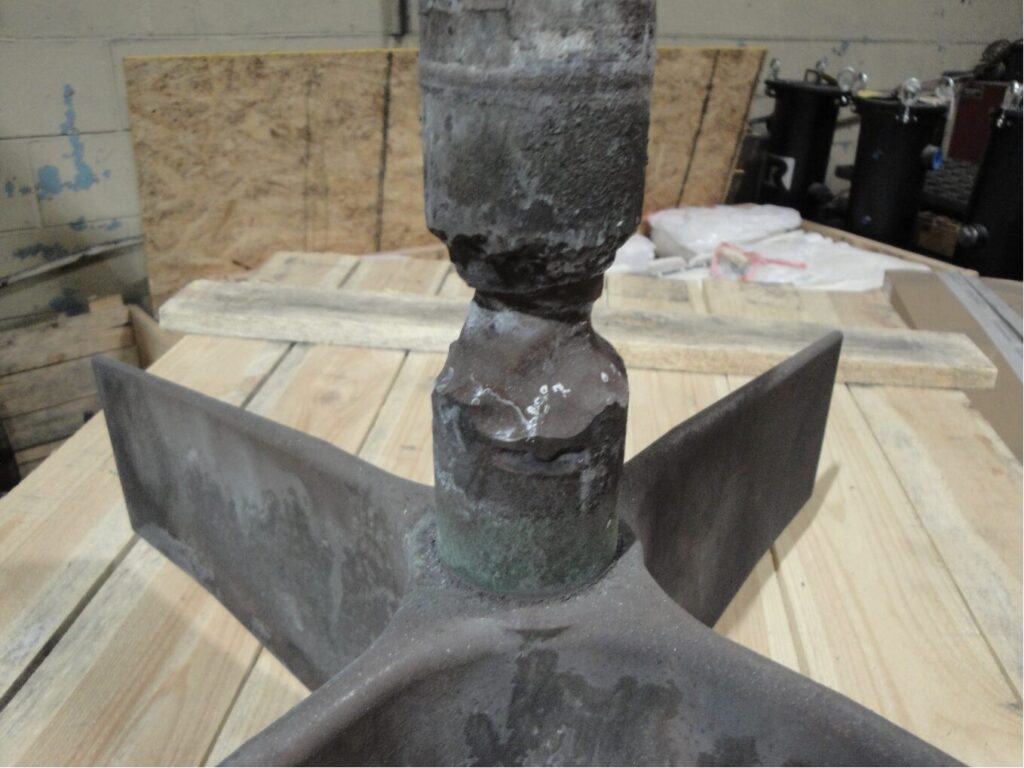
Examples of Catastrophic Carburization (a.k.a. Metal Dusting)
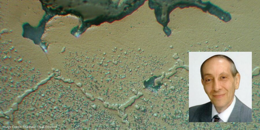
Figure 1. Pusher furnace alloy fan and shaft assembly | Image Credit: The Heat Treat Doctor®
Metal dusting (Figure 1) is a hot gaseous corrosion phenomenon in which a metallic component disintegrates into a dust of fine metal and metal oxide particles mixed with carbon.
Generally, metal dusting occurs in a localized area, and how rapidly the disintegration progresses is a function of temperature, the composition of the atmosphere and its carbon potential, and the material. Other significant factors include the geometry of the system, reaction kinetics, diffusivities of alloy components, the specific-volume ratio of new and old phases, and the ultimate plastic strain.
Metal dusting usually manifests itself as pits or grooves on the surface, or as an overall surface attack in which the metal can literally be eaten away in a matter of days, weeks, or months. As an example, this writer has seen a 330-alloy plate mounted underneath a refractory-lined inner door of an integral quench furnace (where atmosphere passes underneath the door and into the quench vestibule) reduced in thickness from 12.5 mm (0.50 in) to less than 0.75 mm (0.03 in) in a little over two months.
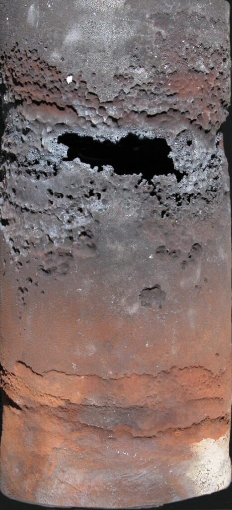
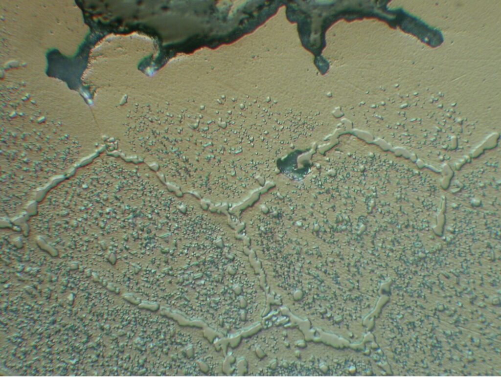
Figure 2. 330 alloy radiant tube removed after six months of use (rotary retort furnace) | Image Credit: The Heat Treat Doctor®Figure 3. Microstructural view: catastrophic carburization | Image Credit: The Heat Treat Doctor®
In another example, a metallographic investigation performed by this writer on a failed wrought 330 alloy radiant tube (Figure 2) was conducted. Optical microscopy of the inside (Figure 3) and outside diameter surfaces in the attacked area revealed evidence of massive carbides. These carbides are formed by the reaction of carbon with chromium, depleting the matrix of chromium in regions adjacent to the carbides. Grain detachment and subsequent failure by erosion then occurred.
How Does It Occur?
In general, catastrophic carburization of ferrous alloys proceeds via the formation and subsequent disintegration of metastable carbide. The first step in the process is absorption of the gaseous phase on the surface of the metal; the more reactive this phase, the easier it decomposes or is catalytically decomposed (in the case of iron) on the surface. This step is followed by diffusion of carbon atoms from the surface into the bulk metal.
As a result, there is a continuous buildup of carbon within the surface layer. As this layer becomes saturated with carbon, a stable carbide, metastable carbide, or an active carbide complex forms, which then grows until it reaches a state of thermodynamic instability, at which point it rapidly breaks down into the metal plus free carbon.
It’s at this stage that the metal disintegrates to a powder as the result of plastic deformation and subsequent fracture in the near-surface layer. The process is controlled by internal stresses due to phase transformation; in other words, competition between stress generation and relaxation exceeds the ultimate strength in this near-surface layer and causes fracture to occur.
In Ni-Cr-Fe alloys, the phenomenon occurs slower (but does not stop) since the disintegration leads to larger metal particles, which are less active catalysts for carbon deposition than the fine iron particles that form with ferrous metals. Therefore, the mass gain from carbon depositing onto high-nickel alloys is much lower. Also, the decomposition of high-nickel alloys occurs by graphitization and not via unstable carbides.
Pourbaix-Ellingham Diagrams
Thermodynamics can be applied to solid-gas reactions to obtain equilibrium dissociation pressures below which no reactions occur. Data and diagrams are available for the free energies of formation versus temperature for most metallic compounds. An interesting use of Pourbaix diagrams (generally reserved for mapping out possible stable equilibrium phases of an aqueous electrochemical system) as a predictor of stable alloy systems is found by superimposing the various elemental constituents. These diagrams are read much like a standard phase diagram (with a different set of axes).
In Summary
Hot gaseous corrosion should be an area of focus for every heat treater to extend the life of alloy components, reduce downtime, and save money. Mitigation in the form of alloy selection, equipment design, type of atmosphere, process/cycle selection, and idling temperatures will play a huge role in extending the life of our furnace alloys, baskets, and fixtures.
References
ASM International. 1971. Oxidation of Metals and Alloys.
Nateson, K. 1980. Corrosion–Erosion Behavior in Metals. Warrendale, PA: Metallurgical Society of AIME.
National Bureau of Standards. 1978. Gas Corrosion of Metals.
Pourbaix, Marcel. 1974. Atlas of Chemical and Electrochemical Equilibria in Aqueous Solutions. Houston, TX: NACE International.
Pourbaix, Marcel. 1998. Atlas of Chemical and Electrochemical Equilibria in the Presence of a Gaseous Phase. Houston, TX: NACE International.
Schweitzer, Philip A. 1996. Corrosion Engineering Handbook. New York: Marcel Dekker.
Staehle, R. W. 1995. “Engineering with Advanced and New Materials.” Materials Science and Engineering A 198 (1–2): 245–56.
Stempco, Michael J. 2011. “The Ellingham Diagram: How to Use It in Heat-Treat-Process Atmosphere Troubleshooting.” Industrial Heating, April.
Uhlig, Hubert H. 2008. Corrosion and Corrosion Control. Hoboken, NJ: Wiley-Interscience.
Fabian, R., ed. 1993. Vacuum Technology: Practical Heat Treating and Brazing. Materials Park, OH: ASM International.
The Boeing Company. n.d. “Practical Vacuum Systems Design Course.”
About the Author
Dan Herring “The Heat Treat Doctor” The HERRING GROUP, Inc.
Dan Herring has been in the industry for over 50 years and has gained vast experience in fields that include materials science, engineering, metallurgy, new product research, and many other areas. He is the author of six books and over 700 technical articles.
Today’s Technical Tuesday highlights this first installment in a multi-part series by Nikolai Alexander and The Heat Treat Doctor® Daniel H. Herring, which introduces Inconel® Alloy 718, one of the most widely used nickel-based superalloys, tracing its history, applications, and production fundamentals. Understanding why this alloy performs so well in extreme environments is critical as manufacturers consider material choices available for demanding components, especially alloys more typically sourced outside of one’s own industry. As demanding performance capabilities are being required of new engineered solutions, selecting the right alloy becomes a strategic decision to meet the need for higher temperatures, pressures, and corrosive environments.
This informative piece is fromHeat Treat Today’sFebruary 2026 Annual Air & Atmosphere Heat Treating print edition.
History
Inconel® Alloy 718 (IN 718) is a nickel-iron base superalloy known for its exceptional strength, resistance to high temperatures and ability to withstand harsh environments, where oxidation, creep, and corrosion resistance are paramount. The alloy was created by Dr. Herbert L. Eiselstein, who began his research in 1958, culminating in a patent assigned to The International Nickel Company in 1962 (U.S. Patent No. 3,046,108). In the many years since its creation, IN 718 remains the most widely used of all superalloys due to its availability in both wrought and cast products with high strength and stress-rupture life up to 650°C (1200°F), good hot working characteristics, castability, weldability, and cost effectiveness — all in an alloy with nominally 18% iron! The alloy’s superior performance is due in large part to its unique strengthening mechanisms.
There are different classifications of a superalloy, all based around the predominant metal present in the alloy. These categories include (Akca and Gursel 2015):
Nickel-based
Iron-based
Cobalt-based
The microstructural design makes IN 718 one of the best alloys for service applications below 650°C (1200°F) (Loria 1988, Herring 2011). It is widely used in extreme environments where components are subjected to high temperature, pressure, and/or mechanical loads. When heated, IN 718 forms a thick, stable, passivating oxide layer that protects the surface from further attack.
The alloy retains strength over a wide temperature range, making it attractive for high-temperature applications where materials like aluminum and steel would fail due to creep caused by thermally induced crystal vacancies. Inconel’s high-temperature strength is developed through heat treatment by solutionizing and precipitation hardening.
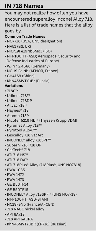
IN 718 is an alloy used around the world, but you might know it better by one of a variety of trade names (see sidebar).
The alloy has been modified numerous times to extend its operating temperature and service life. The alloy is readily available in all of these modified variations, each having slight differences in chemistry, cast and wrought processing methods, and heat treatments.
Applications
There is a wide variety of IN 718 applications across many industries, including aerospace, nuclear, oil and gas, automotive, motorsport, chemical processing, non-nuclear power generation, medical, tooling and molds, and fire protection systems.
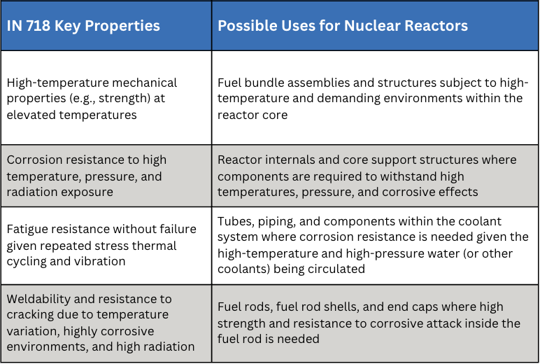
In the automotive and motorsport industry, IN 718 is used for turbocharger rotors, exhaust manifolds, and valve springs in high-performance engines, such as those found in Formula 1 or the 24 Hours of Le Mans race cars. Naval warships are also purported to use IN 718 for components in their nuclear reactors (Table A).
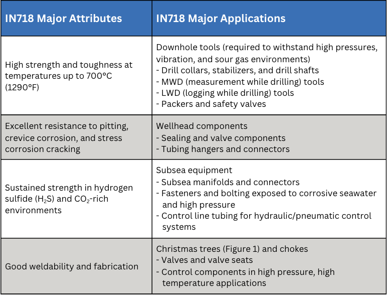
Table A. Possible Uses of IN 718 in Naval Warship Nuclear ReactorsTable B. Oil & Gas Industry Use Examples for IN 718
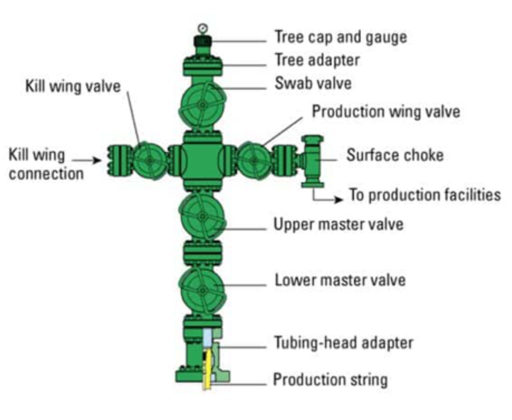
Figure 1. A “Christmas tree”: the complex assembly of valves, gauges, and controls installed at the surface of a completed oil or gas well which has the primary function of regulating and controlling the flow of oil from the well. | Image Credit: Croft Systems
Perhaps surprisingly, IN 718 is also widely used in the oil and gas industry, which in addition to its many other benefits has remarkable resistance to sulfide and chlorine stress corrosion cracking at both high and low temperatures (Table B). Stress corrosion cracking is a failure mechanism that is caused by a combination of environment, a susceptible material, and the presence of tensile stress. Oil and gas applications like downhole tools, wellhead components, and subsea equipment benefit from IN 718’s other valuable properties as well, some of which include:
High strength and toughness at temperatures up to 700°C (1290°F)
Excellent resistance to pitting, crevice corrosion, and stress corrosion cracking
Sustained strength in hydrogen sulfide (H2S) and CO2-rich environments
Good weldability and fabrication
Continuous innovations in processing and material chemistry have enhanced superalloy properties resulting in the extension of its use into other industries, such as the energy and more conventional transportation sectors (Loria 1988).
Production Methods
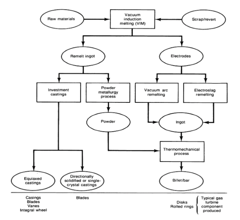
IN 718 is available in cast and wrought alloy form and follows a stringent production process (Figure 2). Basic melt practices are used, such as vacuum induction melting (VIM), vacuum arc remelting (VAR), and electro-slag remelting (ESR).
Figure 2. Flow diagram of processes widely used to produce superalloys (Data reference: Akca and Gursel 2015)
VIM
The VIM process produces liquid metal under vacuum in an induction-heated crucible. It is used as a primary melting step in the route to producing wrought and cast products. Before being melted, the raw material can be refined and purified, and its composition can be controlled. VIM has been widely used in the manufacture of all types of superalloys, which must be melted under vacuum or in an inert gas atmosphere because of their reactivity with atmospheric oxygen and nitrogen.
VAR
The VAR process, a secondary melting technique, converts VIM-processed electrodes into ingots whose chemical and physical homogeneity have been significantly improved. In this process, a stub is welded to one end of an electrode, which is then suspended over a water-cooled copper crucible. Next, an arc is struck between the end of the electrode and the crucible bottom. Maintaining the arc generates the heat required to melt the electrode, which drips into the crucible and can subsequently be poured into molds. Many inclusions can be removed by flotation or chemical and physical processes before the molten material solidifies.
ESR
The ESR process, another secondary melting technique, is similar to the VAR process, but with notable differences. Remelting does not occur by striking an arc under vacuum. Instead, an ingot is built up in a water-cooled mold by melting a consumable electrode that is immersed in a slag, which is superheated by means of resistance heating. Rather than operating in a vacuum, the process is conducted in air under the molten slag. During melting, metal droplets fall through the molten slag, and chemical reactions reduce sulfur and nonmetallic inclusions. Both ESR and VAR processes allow directional solidification of an ingot from bottom to top, yielding high density and homogeneity in its macrostructure, as well as an absence of segregation and shrinkage cavities.
Casting Methods
IN 718 can also be produced by several casting methods. The most common of these are investment casting and (vacuum) die casting:
Investment casting: This process involves creating a wax pattern, coating it with a ceramic shell, melting out the wax, and then pouring molten IN 718 into the ceramic mold.
Vacuum die casting: This method uses a vacuum to fill the mold, resulting in a refined grain structure, minimal porosity, and good dimensional reproducibility, making it suitable for components like airfoils.
Sand casting: This method is far less common due to its inherent limitations in precision and surface finish, but the technology has been used for large castings.
A Metallurgical Perspective: The Role of Gamma Prime and Double Prime
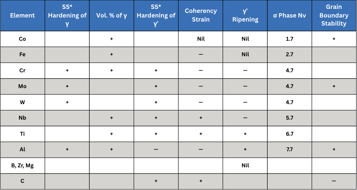
IN 718 is a precipitation hardening superalloy. Its principle strengthening phases are gamma prime (γ′) or Ni3Al and gamma double prime (γ″) or Ni3Nb. The relationship between these precipitates (and others) and the gamma (γ) nickel matrix is critically important. For example, the coherency strain (i.e., the elastic deformation that occurs between two phases when their lattice structures do not perfectly match) is due to the fact that γ′ is face-centered cubic and γ″ is body centered tetragonal. In the case of IN 718, these strengthening effects are influenced more by γ″ than γ′ (ASM International 2016, Lee et al. 2023).
In addition, IN 718 has a natural tendency to precipitate rapidly by homogeneous nucleation in the noncompressible γ matrix. Depending on chemistry, γ′ volume percentage can vary over a wide range (3%–65%). Practically speaking, creep strength is proportional to volume percent over this range at temperatures between 700–980°C (1290–1800°F). As a result, the ratio of titanium to niobium/aluminum is key to hardening. High ratios imparted by niobium assure high strength at intermediate service temperatures around 600°C (1110°F). For higher service temperatures, higher aluminum content and molybdenum additions minimize the γ and γ′ mismatch, thus contributing to more stable alloys (Decker 2006, Guan et al. 2023).
Finally, the size and shape of these precipitates is important; larger precipitates enhance the strengthening effect. Key to the formation of these two precipitates is the aging treatment temperature, time, and alloy composition. According to existing research, higher aging treatment temperatures and longer times can lead to an increased amount of γ″ while extended aging coarsens the γ′ and γ″ particles, potentially leading to a reduction in strength and creep resistance. Furthermore, the composition ratios of Al, Ti, and Nb in the alloy influence the shapes of γ′ and γ″ precipitates, forming so-called co-precipitates that also affect the properties (Table C).
*SS = solid solution; + = enhancement; — = negative effect Table C. Effect of Various Alloying Elements (Data Reference: Decker 2006)
The highest strength and hardness, coupled with reduced impact toughness, have been observed after heat treatment at 718°C (1325°F), due to an increase in the size and quantity of γ′ and γ″ precipitates.
In addition, as a result of surface analysis of Charpy bars, intergranular fracture occurs due to abundant small-sized precipitates formed within the boundary. In the case of the Charpy impact test, the absorbed energy decreases as the aging temperature increases. The formation of carbide, γ′ and γ″ precipitates can reduce the impact toughness of materials because precipitates may cause more obstacles to dislocation movement and promote crack initiation and propagation (Lee et al. 2023).
This article’s discussion continues in Heat TreatToday’sAnnual Aerospace Heat Treat (March 2026) print edition to address heat treatment methods for this superalloy.
References
Akca, Enes, and Gursel, Ali. 2015. “A Review on Superalloys and IN718 Nickel-Based INCONEL Superalloy.” Periodicals of Engineering and Natural Sciences 3 (1): 15–27.
Babu, S. S., N. Raghavan, J. Raplee, S. J. Foster, C. Frederick, M. Haines, R. Dinwiddie, M. K. Kirka, A. Plotkowski, Y. Lee, and R. R. Dehoff. 2018. “Additive Manufacturing of Nickel Superalloys: Opportunities for Innovation and Challenges Related to Qualification.” The Minerals, Metals & Materials Society and ASM International: 3764–3780.
Chandler, Harry, ed. 1996. Heat Treater’s Guide: Practices and Procedures for Nonferrous Alloys. ASM International.
Croft Systems. n.d. “The Difference between a Wellhead & Christmas Tree.” https://www.croftsystems.net/oil-gas-blog/the-difference-between-a-wellhead-christmas-tree/
Decker, R. F. 2006. “The Evolution of Wrought Age-Hardenable Superalloy.” Journal of The Minerals, Metals & Materials Society, September: 32–36.
del Bosque, Antonio, Fernández-Arias, Pablo, and Vergara, Diego. 2025. “Advances in the Additive Manufacturing of Superalloys.” Journal of Manufacturing and Materials Processing 9 (215): 1–31.
Eliasen, K. M., T. L. Christiansen, and M. A. J. Somers. 2010. “Low-Temperature Gaseous Nitriding of Ni-Based Superalloys.” Surface Engineering 26 (4): 248–255.
Guan, Hao, Wenxiang Jiang, Junxia Lu, Yuefie Zhang, and Ze Zhang. 2023. “Precipitation of δ Phase in Inconel 718 Superalloy: The Role of Grain Boundary and Plastic Deformation.” Materials Today Communications 36 (August).
Herring, Daniel H. 2011. “Stress Corrosion Cracking.” Industrial Heating, October: 22–24.
Herring, Daniel H. 2012. Vacuum Heat Treating: Principles, Practices, Applications. BNP Media II, LLC.
Herring, Daniel H. 2019. “The Heat Treatment of Inconel 718.” Industrial Heating, June: 12–14.
Lee, Gang Ho, Ang Ho, Minha Park, Byoungkoo Kim, Jong Bae Jeon, Sanghoon Noh, and Byung Jun Kim. 2023. “Evaluation of Precipitation Phase and Mechanical Properties According to Aging Heat Treatment Temperature of Inconel 718.” Journal of Materials Research and Technology 27 (Nov–Dec): 4157–4168. https://doi.org/10.1016/j.jmrt.2023.10.196
Lee, Shin-Chin, Shih-Hsien Chang, Tzu-Piao Tang, Hsin-Hung Ho, and Jhewn-Kuang Chen. 2006. “Improvements in the Microstructure and Tensile Properties of Inconel 718 Superalloy by HIP Treatment.” Materials Transactions 47 (11): 2877–2881.
Loria, Edward A. 1988. “The Status and Prospects of Alloy 718.” Journal of Materials, July: 36–41.
Polasani, Ajay, and Vikram V. Dabhade. 2024. “Heat Treatments of Inconel 718 Nickel-Based Superalloy: A Review.” Metals and Materials International: 1204–1231.
Sharghi-Moshtaghin, Reza, Harold Kahn, Yindong Ge, Xiaoting Gu, Farrel J. Martin, Paul M. Natishan, Arrell J. Martin, Roy J. Rayne, Gary M. Michal, Frank Ernst, and Arthur H. Heuer. 2010. “Low-Temperature Carburization of the Ni-Base Superalloy IN718: Improvements in Surface Hardness and Crevice Corrosion Resistance.” Metallurgical and Materials Transactions A 41A (August): 2022–2032. https://doi.org/10.1007/s11661-010-0299-y
Shipley, Jim. 2023. “Hot Isostatic Pressing and AM: How to Improve Product Quality and Productivity for Critical Applications.” Metal AM 9 (3).
U.S. Patent No. 3,046,108.
Acknowledgments: This paper would not have been possible without discussions, guidance and contributions from a number of individuals in both the heat treat industry and academia.
Dan Herring “The Heat Treat Doctor®” The HERRING GROUP
Dan Herring, who is most well known as The Heat Treat Doctor®, has been in the industry for over 50 years. He spent the first 25 years in heat treating prior to launching his consulting business, The HERRING GROUP, in 1995. His vast experience in the field includes materials science, engineering, metallurgy, equipment design, process and application specialist, and new product research. He is the author of six books and over 700 technical articles.
Nikolai Alexander Hurley Intern The Heat Treat Doctor®
Nikolai Alexander Hurley is a young academic, interning with The Heat Treat Doctor®.
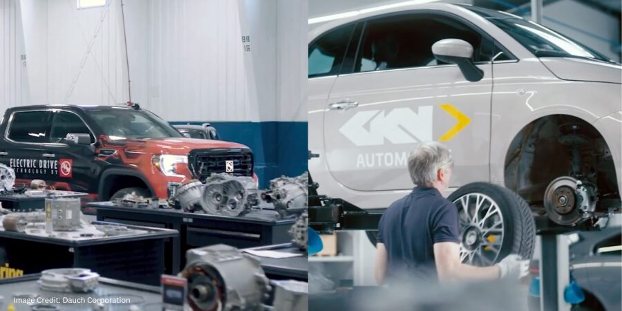
Dauch Corporation has completed its acquisition of Dowlais Group plc, combining two global automotive manufacturers in a move that expands driveline, metal forming, and powder metallurgy operations worldwide. The transaction broadens manufacturing capabilities and strengthens support for internal combustion, hybrid, and electric vehicle platforms across global markets.
David C. Dauch Chairman and CEO Dauch Corporation Image Credit: Detroit Regional Chamber
Dauch Corporation finalized its previously announce acquisition of Dowlais Group plc, including subsidiaries GKN Automotive and GKN Powder Metallurgy. David C. Dauch, chairman and chief executive officer, said the closing marks an important step in bringing together complementary engineering and manufacturing capabilities under one organization.
The combined business will operate under the Dauch Corporation name and remain headquartered in Detroit. The board of directors will expand to include Simon Mackenzie Smith and Fiona MacAulay as independent directors, effective February 5, 2026.
The leadership structure includes Michael J. Lynch as president of driveline and Markus Bannert as president of metal forming, along with executives overseeing finance, strategy, human resources, communications, and legal functions. Business unit leadership includes Tolga Oal as president of axle systems; Mark Gabriel as president of sideshafts, propshafts, and ePowertrain; Jake Stiteler leading forging operations; and Jean-Marc Durbuis leading powder metallurgy operations.
Dauch Corporation supplies driveline and metal forming products to the global automotive industry and reports operations in 24 countries with more than 175 locations worldwide.
Press release is available in its original form here.