In order to maintain the cleanliness of workpieces and baskets or fixtures in the vacuum heat treating or brazing process, it is helpful to establish a pre-treating cleaning practice. Vapor degreasing has emerged as a cleaning process with the acting principle that the solvents will dissolve the contaminants on the workpiece and remove them by dripping off the part. In this week’s Technical Tuesday article, a Best of the Web feature, we bring you an article from VAC AERO International addressing the development of the process, the steps involved in vapor degreasing, and comparisons with other cleaning methods.
Cleaning in a solvent offers a level of simplicity and forgiveness not seen in aqueous methods. At one time, solvent cleaning was considered mandatory for successful vacuum processing but environmental concerns (VOC and other emissions) and improvements to aqueous systems including drying technology has seen the industry shift to aqueous cleaning as the norm. Today, however, with the advent of vacuum technology, vacuum vapor degreasing has emerged as a viable alternative to aqueous processing.”
A preview:
Vacuum vapor degreaser schematic with operational sequence steps. (“Removal of Entrained Moisture from Powdered Metal Parts Using High-Temperature Solvent and Vacuum” PM2TEC 2003, via VAC AERO International)Main image photo credit/caption: Vacuum Processing Systems LLC (via VAC AERO International) / Typical vacuum vapor degreaser
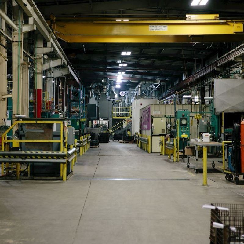
A heat treat and metallurgical services company recently unveiled plans to expand two of their four facilities this summer to better process applications in the aerospace, gears, and firearms industries, among others.
AHT Burton
Advanced Heat Treat Corp. (AHT) announced building expansions for their Monroe, Michigan, and Waterloo, Iowa locations. Michigan AHT plans to increase the size of their pit to accommodate two larger nitriding units, while AHT Burton intends to add square footage for new equipment and related services, such as two recently acquired induction units.
AHT has not expanded the Michigan and Burton facilities since 2006 and 2007, respectively, and hopes to complete the projects by mid-summer. The company also recently increased the shop floor at a third facility which serves as company headquarters in Waterloo, Iowa.
Mike Woods, President, AHT
“We’re very excited about the growth AHT has seen
AHT Michigan
over the past few years,” said AHT President Mike Woods. “Because of this, we felt it was necessary to expand our facilities and invest in additional equipment to better serve our customers and capture more of the market.”
A Minnesota company recently added an aluminum extrusion press and plans to expand its facility to accommodate the new purchase.
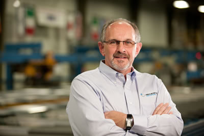
Tom Schabel, CEO, Alexandria Industries
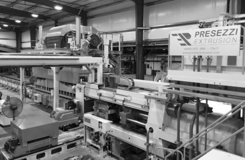
Minnesota manufacturer Alexandria Industries recently invested in a new aluminum extrusion press made by Italian company Presezzi Extrusion Group. Alexandria Industries hopes the press will allow the company to increase its aluminum extrusion capabilities, extrude more complex product features, and hold tighter tolerances, while utilizing a variety of alloys.
“This investment also aligns with our company vision and commitment to excellence,” said Tom Schabel, CEO, Alexandria Industries. “The new system will provide robust extruded aluminum components for our customers, while providing us continued business growth into the future.”
Presezzi Extrusion
Alexandria Industries will work with Presezzi Extrusion to customize the press to meet specific needs of the company. The press will be equipped with new automation and mechanical technology, including:
a magnetic billet heating system
the ability to push harder alloys
automation, quench, and safety management systems
an automated log handling and washing system
Bruno Donada, area manager, Presezzi Extrusion Group
“We are delighted to be working with Alexandria Industries to provide our latest advancements in extrusion system technologies,” said Bruno Donada, area manager, Presezzi Extrusion Group. “The company’s collaborative culture fits perfectly with the way we run our business. This new partnership will generate business opportunities in the high-value aluminum extrusion industry for both companies.”
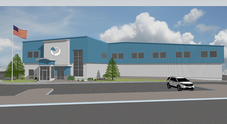
Alexandria Industries Building Addition
To accommodate the new press along with its Kevlar handling system, the company plans to add 19,000 square feet of space to its manufacturing facility located in Alexandria, Minnesota.
A large Ohio manufacturer of bearings and power transmissions recently purchased an established roller chain company to enhance their distribution and manufacturing services.
The Timken Company, producer of engineered bearings and power transmissions, acquired The Diamond Chain Company from Amsted Industries. Based in Indianapolis, Indiana, Diamond Chain supplies high-performance roller chains for industrial markets for a range of sectors, including industrial distribution, material handling, food and beverage, agriculture, and construction.
The Diamond Chain Company
When heat treating their components, Diamond Chain uses dedicated carburizing furnaces set to precise temperatures. To produce maximum carbon penetration for a high carbon surface and low carbon core, the company strives to closely control atmosphere and quench. This process is designed to achieve consistent depth of case hardening increasing strength, durability, and wear resistance.
Richard G. Kyle, Timken President and Chief Executive Officer
“The acquisition of The Diamond Chain Company adds another strong industrial brand with a reputation for quality, reliability and performance to Timken’s growing power transmission portfolio,” said Richard G. Kyle, president and chief executive officer at Timken. “Diamond Chain is a premier brand in the North American distribution channel and is an excellent strategic fit with our Drives chain business. The acquisition expands our leadership in roller chain, builds on our strong position in distribution and adds depth to our manufacturing capabilities in Asia. We expect to drive significant synergies with the combination of Diamond Chain and Drives.”
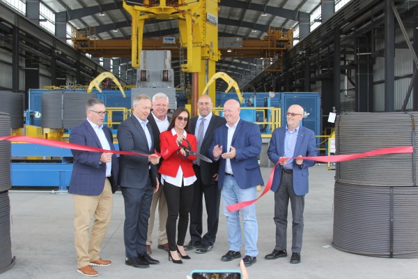
A steel manufacturer recently opened an addition to its Mesa, Arizona, facility featuring the necessary space and equipment to add spooled rebar to their line of products.
The ribbon-cutting ceremony for CMC Steel Arizona’s Expansion. (City of Mesa)
Commercial Metals Co. announced the opening of their 63,000-square-foot expansion and manufacturing line to produce spooled rebar at CMC Steel Arizona, a micro mill in southeast Mesa.
The company’s commitment to produce hot-rolled, spooled rebar at the Mesa mill makes it CMC’s second U.S. spooler operation. The first opened last year in Durant, Oklahoma.
CMC Steel Arizona also manufactures concrete reinforcing bar, or rebar, and steel t-posts, which are primarily produced from recycled scrap metal.
“CMC commitment to innovation and new technology makes them a leader in the steel production, fabrication and recycling industry.” – John Giles, Mayor of Mesa
The parent company of a U.S.-based induction heating equipment manufacturer was selected to supply an induction heating system to an international fan manufacturer, replacing their aging heating system with a UNI HEAT system.
Elektror, headquartered in Ostfildern, Germany, purchased the induction heating system from EMAG eldec, the parent company of eldec LLC, a heating equipment supplier in Auburn Hills, Michigan. Elektror has two production sites in Waghäusel, Germany, and Chorzów, Poland, and creates industrial fans and side channel compressors. The Waghäusel site, which manufactures nearly 250 devices a day, purchased the UNI HEAT from EMAG eldec in hopes of achieving precise induction heating of motors for their fans.
Induction heating is used to manufacture the electric motors that drive Elektror’s fans and side channel compressors by combining the empty stator housing and the motor winding. To achieve this, the housing is first heated to a temperature of 280 to 300 degrees Celsius. This causes it to expand and allows for the motor winding to be inserted. Once they have cooled down, both components establish a form-fitting and solid bond. Although Elektror used the joining process previously, their former induction heating system was in need of improvement. For instance, it did not indicate the component’s actual temperature after heating, which led to extended throughput times when joining the empty stator housing and the motor winding. The company hoped to improve this process and make it more reliable.
Roland Sand, head of the production team at Elektror, found Emag Eldec with an Internet search for potential suppliers that would have the required expertise and proximity to Waghäusel to deliver timely service. His company then visited the EMAG eldec site in Dornstetten and discussed the project. “In the end,” he said, “it was EMAG eldec’s extensive experience with induction turn-key solutions that convinced us.”
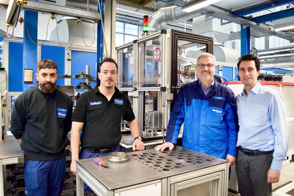
Roland Sand (2nd from left) with colleagues at Elektror and a representative from EMAG eldec (Source: EMAG eldec).
The two companies collaborated on subsequent development of the UNI HEAT system. They worked out details regarding the control unit, safety, and the design of the new comprehensive solution, including a modified induction heating process. To ensure precise heating results, they set an induction rod to plunge into the hollow component rather than using a ring inductor, which enclosed the component from outside.
They implemented several steps to develop process reliability. First, the operator places the empty housing in the custom-fit workpiece carrier and pushes it inside the UNI HEAT. As soon as he closes the front door, the first mechanical processes are initiated in the machine; the component is lifted and encompasses the inductor when it reaches its processing position. The actual induction heating then only lasts 30 to 120 seconds depending on the size of the housing. When complete, a warning light signals to the operator that the component can be removed. The actual component temperature is continuously shown on the operator panel.
The operator then places the hot housing on a mold, which is ready at the cooling location. He pushes the motor winding from the top into the housing. The component is cool in approximately two minutes and then placed on a conveyor belt.
The machine undergoes many retooling processes, because Elektror produces a variety of motor sizes, and sometimes the batches change several times a day. The process is brief; the operator loosens two screws on the inductor mount, removes the inductor and attaches one of six different inductors for the various empty housings. The workpiece carrier is simply set down and can be changed easily in a few seconds. The program on the operator panel can be set in just a few clicks, which completes the process.
Dr. Mihails Scepanskis is the CEO and co-founder of CENOS LLC.
Induction heating is an efficient way to quickly heat electrically conductive metals with pinpoint accuracy. It starts very simply, with a coil of conductive material, however initial design and optimization of the process are very complicated—it's hard to predict power, frequency, and heating time to get necessary results.
Computer simulation for induction heating is a powerful tool that enables engineers to investigate or design a physical system and process using a virtual mathematical model, thus saving time and money on numerous physical design iterations.
Dr. Vadims Geza is the chief scientist at CENOS.
Induction heating computer simulation offers the most efficient means of developing customized and optimized solutions and is, therefore, a necessity—not a luxury—in the modern induction heating industry. In this article, Dr. Mihails Scepanskis and Dr. Vadims Geza, both of CENOS LLC, based in Riga, Latvia, list features and benefits, obstacles and solutions of induction heating; advantages and disadvantages of computer simulation vs physical testing; what should be taken into account when choosing the right simulation software.
How simulation software can help companies save time and money on induction coil and process design
About Induction Heating
Today induction heating is used in many industrial processes, such as heat treatment in metallurgy, crystal growth and zone refining used in the semiconductor industry, and to melt metals which require very high temperatures.
Where Is Induction Heating Used?
Automotive
Construction
Aerospace
Metallurgical Plants
Oil & Gas Component Manufacturing
Special Applications
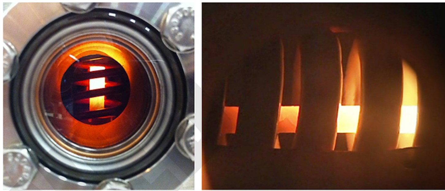
NASA's experimental NTP fuel elements heated with induction (Photo: CENOS)
Features:
Heat generation occurs inside the part.
Heating is contactless—as a result, product warpage, distortion and reject rates are minimized.
This method can provide very high power densities.
Heating may be highly selective in the depth and along the surface.
Any processing atmosphere (air, protective gas, vacuum) can be applied.
Very high temperatures may be reached.
The general benefits of induction surface heat treatment are
Short heating times—production rates can be maximized.
Optimized consistency—induction heating eliminates the inconsistencies and quality issues associated with open flame, torch heating, and other methods.
Extended fixture life—induction heating delivers heat to very small areas of your part without heating any surrounding parts. This extends the life of the fixturing and mechanical setup.
Environmentally sound without burning fossil fuels—induction is a clean, non-polluting process. Improves working conditions for employees by eliminating smoke, waste heat, noxious emissions, and loud noise.
Effective energy consumption—this uniquely energy-efficient process converts up to 90% of the energy expended energy into useful heat; batch furnaces are generally only 45% energy-efficient. Requires no warm-up or cool-down cycle.
Flexible adaptation to the hardening tasks
Closed loop computerized process control and compatibility with overall process automation
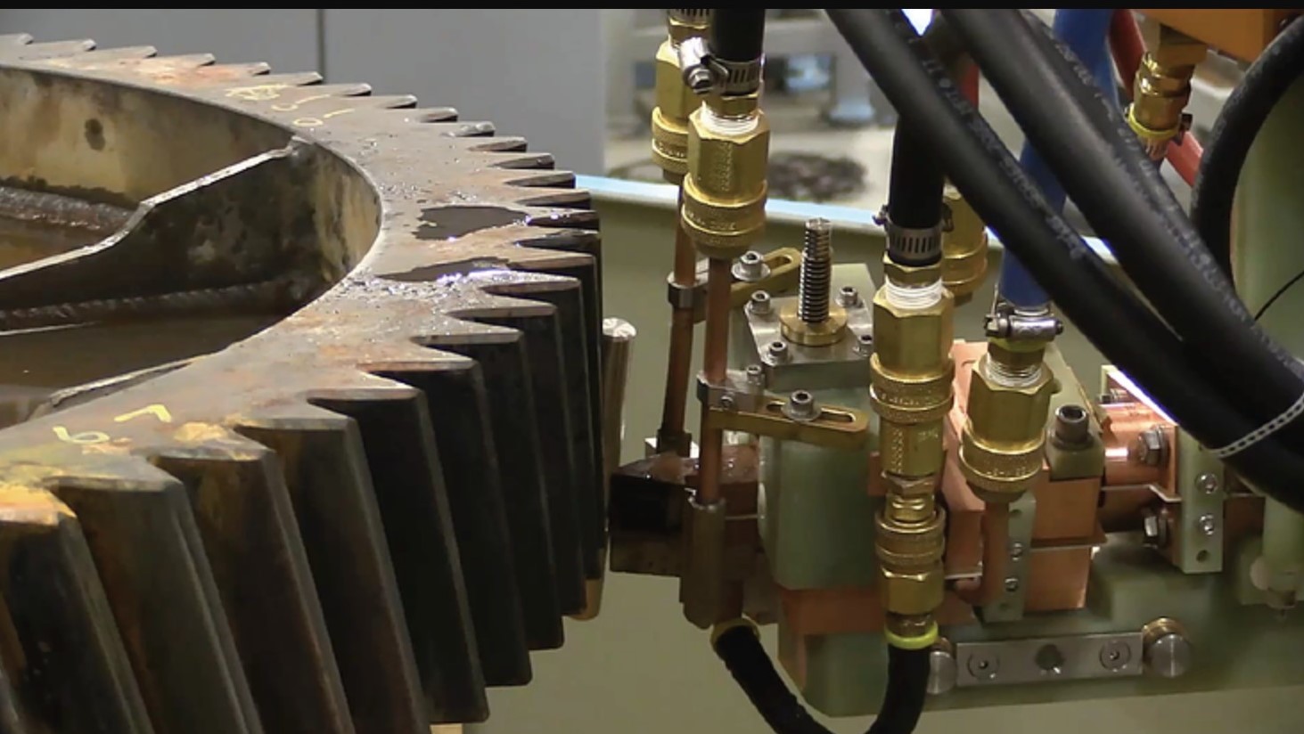
Large gear heat treatment (Photo: CENOS)
Obstacles:
Initial design and optimization of the process is very complicated.
It is hard to predict power, frequency and heating time to get necessary results.
Unlike other heating methods, induction heating requires specific coil design for each workpiece, so it's not very economic unless you need to process multiple similar workpieces.
To design and calculate the induction heating process you can:
Do a rough analytical estimation, then proceed with countless design iterations in the lab.
Find a professional company that can do induction coil and process design for you, but keep in mind that you most likely will be charged for design hours spent in the lab.
Buy a sophisticated multi-physics simulation software and hire a trained simulation engineer/analyst or pay for engineer's training (usually takes 3 months).
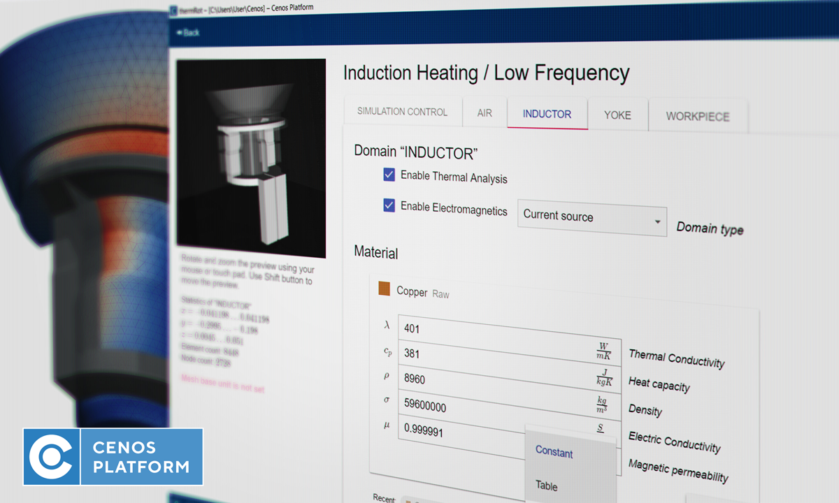
Start using a simple, affordable, and induction heating-focused simulation software like CENOS Platform, which features online training and templates for a quick and easy start.
Induction Heating and Computer Simulation
What Is a Computer Simulation?
Nowadays, in various industries, manufacturers prefer using software simulations over physical testing. Computer simulation is a powerful tool that enables engineers and scientists to investigate or design a physical system and/or process using a virtual mathematical model, thus saving time and money on numerous physical design iterations.
The vast majority of modern computer simulation software packages utilize numerical methods (e.g. finite element method or “FEM”) to evaluate extremely complex physical systems—systems that are otherwise impossible to precisely analyze. By leveraging the power of modern computer hardware, simulation software can provide substantial improvements in the efficiency, reliability, and cost-effectiveness in design and development processes.
Computer Simulation in Induction Industry
First works on computer simulation of induction coils were made in the 1960s. Due to limited access to computers, their low memory, speed, and poor programming methods, the computer simulation did not receive significant industrial application until the 1980s.
Now computer simulation has become a practical tool for everyday use in the induction industry. It allows the user to design optimal systems, improve equipment performance, dramatically reduce development time and costs, and better understand the process dynamics, etc.
Though there are still difficulties in an accurate simulation of non-linear and different mutually coupled tasks, computer simulation is effectively used for the design of induction heating coils and problem solution.
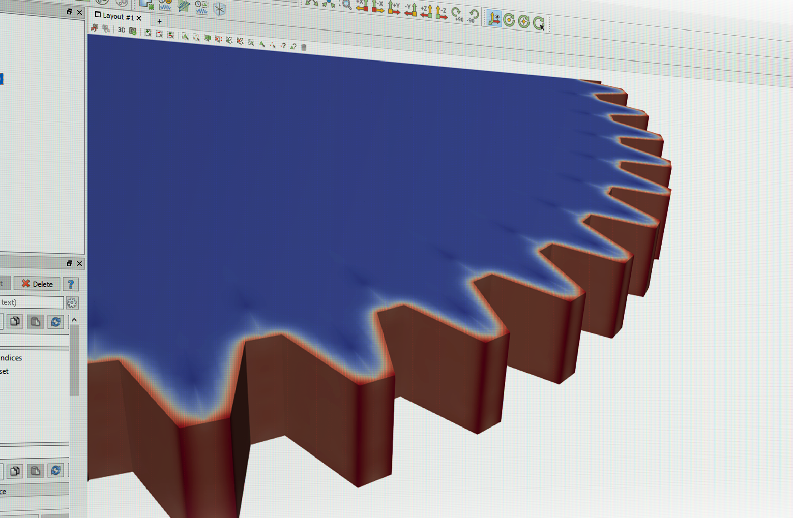
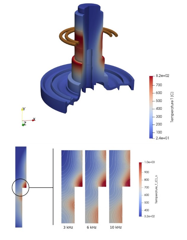
The 10 cm gear hardening with one concentric inductor at 170 kHz and 1.9 kA over 120 ms
Benefits and Value of Induction Heating Computer Simulation
The use of induction heating computer simulation software can promote substantial improvements in the performance and cost-effectiveness of induction heating equipment, in addition to large reductions in the cost and time required to design and develop induction heating processes.
From a design perspective, computer simulation is valuable for a number of reasons, two of the most notable being:
The physics involved in utilizing electromagnetic induction as a deliberate and controlled source of heat generation is extensive and multi-faceted. Computer simulation provides a quantitative approach to designing and developing induction heating processes, allowing complex physical phenomena that cannot be physically observed and/or measured to be clearly visualized and quantified.
Because electromagnetic induction offers an extremely effective, economical, and versatile means of heating conductive materials, the scope of induction heating applications is very broad. This includes (but is not limited to):
Furthermore, each of these general applications includes countless different workpiece types, geometries, materials, and heating requirements. As a result, no “universal solution” exists in the design of induction heating equipment. Induction heating computer simulation offers the most efficient means of developing customized and optimized solutions and is, therefore, a necessity—not a luxury—in the modern induction heating industry.
Combining Simulation With Real World Tests for the Best Results
Example of simulation results (Photo: CENOS)
Inductor design is one of the most important aspects of the overall induction heating system. A well-designed inductor provides the proper heating pattern for your part and maximizes the efficiency of the power supply, while still allowing easy insertion and removal of the part. With the right design, it's possible to heat conductive materials of any size and form, or only the portion of material required.
Computer Simulation vs Experimental Method
Computer Simulation
Advantages
Can work for any geometry and operating conditions
Demonstrates the entire dynamics of the process
Leaves records for future
Limitless accuracy of calculations
Does not require special equipment
Less expensive and less time-consuming
Future improvements expected
Provides 3D process visualization for customers (pictures, video)
Limits and Disadvantages
Requires special software and databases
Not all the processes may be simulated (as of today)
Does not provide physical samples
Experimental Method
Advantages
May provide the most reliable results
Can show the performance of the whole system including unexpected effects and troubles
Does not require a material property database
Provides physical samples for properties validation
Limits and Disadvantages
May require expensive equipment
Does not provide a good understanding of the process
Difficult to transfer knowledge (to scale a company)
Case dependent accuracy
Limited access to production equipment (expensive)
Time-consuming—may cause production delay due to multiple design iterations.
Challenges in coil design
The induction coil, also known as an "inductor", is essential to induction heating. Single-turn, flexible, multi-turn cylindrical, left-turn, right-turn, rod-shaped, hair-pin, parallel, ear-shaped, tiny, big—whatever the coil shape and size—the right design maximizes the lifetime of the coil and ensures lowest energy consumption and best effects on work process and materials.
Many factors contribute to a coil’s effectiveness: the care taken to make it, the quality of the materials used, its shape, its maintenance, its correct matching with the power source, etc.
Here are just three of the many hurdles to be overcome in order to make safe and efficient coils:
Impedance matching
It is necessary to achieve the correct impedance matching between the coil and the power source in order to use the latter’s full power. The coil designer must also consider that coils need five to ten times as much reactive as active power.
Magnetic flux concentrators
Concentrators focus the current in the coil area facing the workpiece. Without concentrators, much of the magnetic flux may propagate around the coil. This flux could engulf adjacent conductive components. But when concentrated, the flux is restricted to precise areas of the workpiece.
Water flow and speed
It is generally important to achieve an adequate flow of cooling water through the coil. When high power density is expected in the inductor, the coil designer must consider the flow rate and the water’s velocity. This is because velocity significantly influences the heat transfer between inductor and coolant and therefore has a major impact on the longevity of the coil. A booster pump is sometimes needed to maintain the desired flow and velocity. Professional designers will also specify a purity level for the water in order to minimize coil corrosion.
Tools and Processes Necessary To Ensure Coil Longevity and Performance
Advanced induction coil design includes:
Detailed analysis of specifications, available equipment, and environment
Coil style and heating process selection (scanning, single-shot, static, etc.)
3D design programs and computer simulation for coil head optimization
Analysis of benefits of magnetic flux controllers application
Advanced manufacturing techniques, mandrels to achieve tight tolerances
Testing in a laboratory or industrial plant for performance and final dimensional check
Final corrections if required
Designing and making induction coils is technically challenging. Computer simulation helps tackle some of the challenges, limiting costs and maximizing effectiveness.
CENOS Platform's mission is to help companies switch from old and cumbersome experimental methods to a powerful computer simulation that is simple, affordable, and induction heating-focused. CENOS, combined with real-world trials, will yield the best results in a fast and cost-effective way.
How To Choose the Right Simulation Software
The induction heating market is small compared to other industrial sectors, and there are only a few specialized simulation packages on the market that can be used for induction process and coil design. Induction heating simulation involves a set of mutually coupled non-linear phenomena. Many induction applications are unique and may require different program modules. In addition to computer simulation software, an extensive material database is necessary for accurate results.
1D, 2D or 3D?
Majority of practical simulations now are being made in 1D or 2D approaches. But with 1D and 2D, the structure and geometry of real induction systems are often very simplified. In reality, a majority of induction systems are 3D. In addition, interference of induction device and source of power must be considered in many cases. That's why 3D will ensure less space for errors and a more thorough analysis.
Cloud vs Desktop
Working with cloud-based software requires uploading your data to the third party. Frequently induction heating equipment manufacturers are not allowed to share their customer CAD files with a third party due to NDA. Furthermore, while cloud computing may provide increased calculation speed, one should consider the time it takes for uploading the design files and downloading the result files.
Importance of training & support (time, costs)
There is a common opinion that simulation software requires a specially educated (and well paid) simulation engineer/analyst, usually hired only for one kind of task—simulation. This is definitely true for sophisticated multi-physics simulation packages, which might require 3 to 4 months of intense training because of a plethora of numerical aspects which should be taken into account in order to get reliable results in a simulation. However, CENOS 3D desktop software keeps focus solely on induction heating and tries to avoid any unnecessary functionality which might confuse an inexperienced user. By using CENOS-dedicated templates, a beginner can run his first induction simulation in just under 30 minutes and become a pro user with any 3D geometry after 2 weeks of training, guided by CENOS engineers.
Cost
Licensing software can cost $20,000 to $80,000 up front plus additional annual payments in 20% value of purchase price just for support and updates. And that's only for an induction heating module, whereas CENOS's annual license is $7,200 and requires no upfront investment. Alternatively, one could consider a “pay as you go” purchase model, paid by hours, but one must keep in mind that 3D calculations take time, which might make this particular subscription model cost inefficient.
Open Source software—a free alternative with some drawbacks
Open source is very cost efficient—open source tools like Elmer or GetDP are free to use. However, these tools might require a long training period (6 to 10 months); plus extra steps and routines required for everyday simulation will take up to 1,000 additional hours a year. Overall, open source tools are a solid choice because they are validated by the community but not focused on user experience.
Benefits:
Community. Open source solutions often have thriving communities around them, bound by a common drive to support and improve a solution and introduce new concepts and capabilities faster, better, and more effectively than internal teams working on proprietary solutions.
The power of the crowd. The collective power of a community of talented individuals working in concert delivers not only more ideas but quicker development and troubleshooting when issues arise.
Transparency. Open source code means just that—you get full visibility into the code base, as well as all discussions about how the community develops features and addresses bugs.
Reliability. Because there are more eyes on it, the reliability of open source code tends to be superior as well. Code is developed on online forums and guided by experts. The output tends to be extremely robust, tried, and tested. In fact, open source code now powers about 90% of the internet and is being rapidly adopted across major enterprises for this reason.
Better security. As with reliability, open source software's code is often more secure because it is much more thoroughly reviewed and vetted by the community.
Drawbacks:
Because there is no requirement to create a commercial product that will sell and generate money, open source software can tend to evolve more in line with developers’ wishes than the needs of the end user. For the same reason, they can be less “user-friendly” and not as easy to use because less attention is paid to developing the user interface.
There may also be less support available for when things go wrong – open source software tends to rely on its community of users to respond to and fix problems.
Because of the way it has been developed, open source software can require more technical know-how than commercial proprietary systems, so you may need to put twice as much time and effort into training employees to the level required to use it.
Many different open source solutions are not compatible with each other. Take for example GetDP - an open source finite element solver, its core algorithm library uses its native pre-processing and post-processing tool Gmsh, which frankly, compared to other solutions, is not the best in its class.
CENOS Makes Open Source User-Friendly and Easy To Use
CENOS Platform uses GetDP solver and offers integration with far more superior open source tools like SALOME for pre-processing and Paraview for post-processing, which by default are not compatible with GetDP.
“CENOS” stands for “Connecting ENgineering Open Source”, highlighting its new software approach: connecting the best of open source tools in one seamless user experience. CENOS platform technology enables affordable simulation available for small to midsize companies by connecting third-party open source algorithms GetDP, Salome, and Paraview, developed by strong academic communities involving world top research centers and universities like Sandia National Lab, Imperial College, KU Leuven, and others. The academic world has already built plenty of smart algorithms; there is no need to charge money for the scientific heritage. Use of free open source algorithms makes it possible for CENOS to be affordable for everyone.
The company has built a user-friendly interaction layer and interconnection between previously incompatible separate open source software algorithms. CENOS Platform consists of a user interface, special data optimization procedures including necessary data reformatting for inter-operational compliance ensuring data flow and control between different open source tools. This way CENOS lets engineers save up to 80% of design time by replacing physical prototyping with powerful simulation software which is affordable and easy to use.
About the Authors: Dr. Mihails Scepanskis is the CEO and co-founder of CENOS LLC, based in Riga, Latvia. Dr. Vadims Geza is the chief scientist at CENOS.
Dr. Valery Rudnev, FASM, IFHTSE Fellow, was selected to be the Woodside lecturer at the most recent ASM Detroit Chapter meeting. The Woodside lecture took place on May 13, 2019, at Burton Manor in Livonia, Michigan. The title of the lecture was “Recent Theoretical and Practical Novelties in Induction Heat Treatment“.
Dr. Rudnev serves as Director of Science and Technology at Inductoheat, Inc. Known within the ASM Int’l and among induction heating professionals as “Professor Induction” for his 40+ years of experience in the heat treating industry, Dr. Rudnev centered his Woodside lecture on recent theoretical and practical novelties in induction heat treatment. He also unveiled common mispostulations associated with induction heating and frequently overlooked metallurgical subtleties.
Thermal processing by means of electromagnetic induction continues to grow at an accelerated rate, replacing alternative processes. Today’s metalworking and heat treating industry must quickly adjust to a rapidly changing business environment, maximizing cost effectiveness, process flexibility, and energy efficiency, yet satisfy continuously increasing demands for higher-quality products, equipment longevity, and environmental friendliness.
Induction heating is a multifaceted phenomenon comprising a complex interaction of electromagnetics, heat transfer, circuit analysis, power electronics and metallurgical phenomena that are tightly interrelated. Novel designs have appeared quite regularly.
The Woodside Lecture is named after William P. Woodside, who founded the American Society for Materials (ASM Int’l.) in Detroit in 1913. Each year, the chapter honors an outstanding member of
the ASM community by asking them to give the annual Woodside Lecture.
Dr. Rudnev holds more than 50 patents and inventions (U.S.and International) and has appeared in more than 250 engineering/scientific publications. He also frequently contributes content to Heat Treat Today. His most recent series, “Equipment Selection for Induction Hardening: Continuous and Progressive Hardening” can be found on Heat TreatToday’s website or in Heat Treat Today’s quarterly print editions.
Photo Caption: (from left-to-right) Dr. Robert C. McCune, FASM (Tech Chair of this event), Dr. James Boileau, ASM Detroit Chair 2018-19, and Dr. Valery Rudnev, FASM, IFHTSE Fellow (the Woodside Lecturer)
The parent company of a western Pennsylvania-base heat treat furnace manufacturer recently announced a partnership with a Serbian defense materials manufacturer to supply new heat processing equipment.
Zastava Arms, which manufactures firearms and artillery, based in Kragujevac, Serbia, replaced dated equipment with a new SECO/WARWICK high-temperature box furnace. The new equipment includes tighter temperature uniformity and fully automated temperature controls.
“We chose the SECO/WARWICK technology based on our previous experience and because it fits perfectly with our current Quality Management System by providing real-time controls that ensure a high-quality product and profitable operation,” said Vladan Živković, Manager of Department of Technology with Zastava Arms. “Zastava Arms has been a supplier to the defense industry for many decades and will stay among top defense suppliers thanks to investments in high-quality technology.”
Jarosław Talerzak, Vice President of Thermal Segment at SECO/WARWICK
According to DefenseWeb, the defense industry of Serbia is the largest in the Western Balkans and manufacturers must implement strict standards in order to meet the criteria to get a permit for manufacturing.
“We have enjoyed a long partnership with Zastava Arms and are pleased to continue supplying advanced technology solutions for every heat treatment application,” said Jarosław Talerzak, Vice President of Thermal Segment at SECO/WARWICK. “As a technology partner, we are positioned to support our customer’s growth by offering a wide range of service and equipment options especially for the very demanding industries represented by our partner.”
Main photo credit/caption: MilMag Facebook/Serbian Zastava Arms assault rifle
A Chicago-based manufacturer recently announced the construction of “the world’s largest continuous ERW tube mill,” according to the project’s supplier.
Capable of producing hollow structural sections (HSS) with a size range of 8″ square x 0.750″ wall up to 22″ square x 1″ wall, the new mill, operated by Atlas Tube, a division of Zekelman Industries, will produce square, rectangular, and round structural sections in the mill. The largest rectangular section will be 34″ x 10″ x 1″ wall, and the largest round section will be 28″ OD x 1″ wall. The new mill will produce products to meet or exceed ASTM A500, ASTM A1085, CSA G40 and ASTM A252. This will be the first time ERW sections above 16″ square will be available domestically.
The mill will also be engineered to allow for world-leading full change-over times of less than 60 minutes, as well as special forming and sizing technology for precise dimensional tolerance. Zekelman Industries selected SMS as the supplier for the mill, Kusakabe for the milling cut-off, and Mair for the material handling and packaging line.
Barry Zekelman, CEO of Zekelman Industries
The total project investment is over $150 million — the largest private investment in the U.S. steel industry in the last decade. Frank Lagac, sales manager of welded pipe plants at SMS, noted that it will be the “world’s largest continuous ERW tube mill.”
“At Zekelman, we continue with our long-standing goal of creating, not waiting for, the future, said Barry Zekelman, CEO of Zekelman Industries.
Tom Muth, president of Atlas Tube
“Over the past few years, we have seen the increasing need for larger, domestically produced HSS in the bridge, transportation, and building markets,” said Tom Muth, president of Atlas Tube. “Also, HSS with thicker walls that meet the more stringent width-to-thickness ratio requirements of the AISC Seismic Provisions are in greater demand for lateral bracing systems.”
Brad Fletcher, senior sales engineer for Atlas Tube
“This new mill gives structural engineers new tools to meet the demands of designing and building cost-efficient and safe steel structures,” said Brad Fletcher, senior sales engineer for Atlas Tube.