INSULATION TECHNICAL CONTENT

Temperature Monitoring and Surveying Solutions for Carburizing Auto Components: Thermal Barrier Design

This is the third in a 4-part series by Dr. Steve Offley (“Dr. O”) on the technical challenges of monitoring low-pressure carburizing (LPC) furnaces. The previous articles explained the LPC process and explored general monitoring needs and challenges (part 1) and the use of data loggers in thru-process temperature monitoring (part 2). In this segment, Dr. O discusses the thermal barrier with a detailed overview of the thermal barrier design for both LPC with gas or oil quench. You can find Part 1 here and Part 2 here


Low-Pressure Carburizing (LPC) with High-Pressure Gas Quench – the Design Challenge

A range of thermal barriers is available to cover the different carburizing process specifications. As shown in Figure 1 the performance needs to be matched to temperature, pressure and obviously space limitations in the LPC chamber.


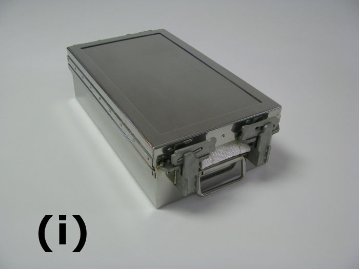
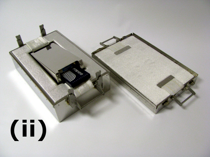
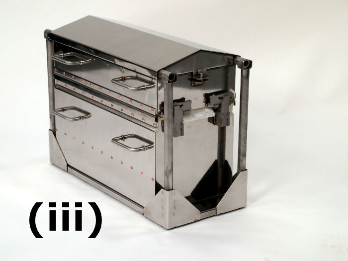
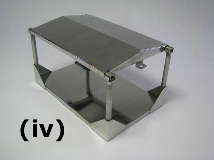
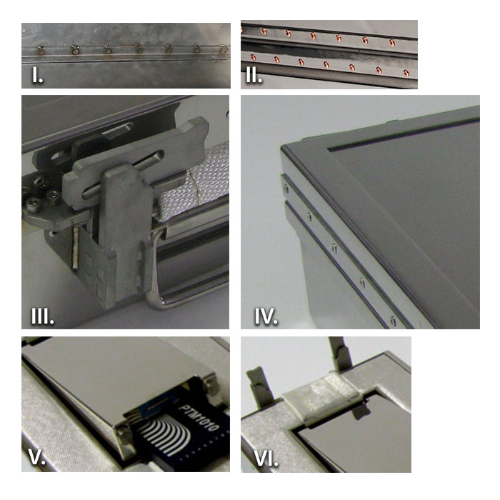
Fig 1: Thermal Barrier Designed Specifically for LPC with Gas Quench.

(i) TS02-130 low height barrier designed for space limiting LPC furnaces with low-performance gas quenches (<1 bar). Only 130 mm/5.1-inch high so ideal for small parts. Available with Quench Deflector kit. (0.9 hours at 1740°F/950°C).

(ii) Open barrier showing PTM1220 logger installed within phase change heatsink.

(iii) TS02-350 High-Performance LPC barrier fitted with quench deflector capable of withstanding 20 bar N2 quench. (350 mm/13.8-inch WOQD 4.5 hours at 1740°F /950°C).

(iv) Quench Deflect Kit showing that lid supported on its own support legs so pressure not applied to barrier lid.

The barrier design is made to allow robust operation run after run, where conditions are demanding in terms of material warpage.

Some of the key design features are listed below.

I. Barrier – Reinforced 310 SS strengthened and reinforced at critical points to minimize distortion (>1000°C / 1832°F HT or ultra HT microporous insulation to reduce shrinkage issues)

II. Close-pitched Cu-plated rivets (less carbon pick up) reducing barrier wall warpage

III. High-temperature heavy duty robust and distortion resistant catches. No thread seizure issue.

IV. Barrier lid expansion plate reduces distortion from rapid temperature changes.

V. Phase change heat sink providing additional thermal protection in barrier cavity.

VI.  Dual probe exits for 20 probes with replaceable wear strips. (low-cost maintenance)


LPC or Continuous Carburizing with Oil Quench – the Design Challenge

Although commonly used in carburizing, oil quenches have historically been impossible to monitor. In most situations, monitoring equipment has been necessarily removed from the process between carburizing and quenching steps to prevent equipment damage and potential process safety issues. As the quench is a critical part of the complete carburizing process, many companies have longed for a means by which they can monitor and control their quench hardening process. Such information is critical to avoid part distortion and allow full optimization of hardening operation.

When designing a quench system (thermal barrier) the following important considerations need to be taken into account.

  • Data logger must be safe working temperature and dry (oil-free) throughout the process.
  • The internal pressure of the sealed system needs to be minimized.
  • The complexity of the operation and any distortion needs to be minimized.
  • Cost per trial has to be realistic to make it a viable proposition.

To address the challenges of the oil quench, PhoenixTM developed a radical new barrier design concept summarized in Figure 2 below. This design has successfully been applied to many different oil quench processes providing protection through the complete carburizing furnace, oil quench and part wash cycles.

Fig 2: Oil Quench Barrier Design Concept Schematic

(i) Sacrificial replaceable insulation block replaced each run.

(ii) Robust outer structural frame keeping insulation and inner barrier secure.

(iii) Internal completely sealed thermal barrier.

(iv) Thermocouples exit through water/oil tight compression fittings.


In the next and final installment in this series, Dr. O will address AMS2750E and CQI-9 Temperature Uniformity Surveys, which often prove to be challenging for many heat treaters. "To achieve this accreditation, Furnace Temperature Uniformity Surveys (TUS) must be performed at regular intervals to prove that the furnace set-point temperatures are both accurate and stable over the working volume of the furnace. Historically the furnace survey has been performed with great difficulty trailing thermocouples into the heat zone. Although possible in a batch process when considering a semi-batch or continuous process this is a significant technical challenge with considerable compromises." Stay tuned for the next article in the series of Temperature Monitoring and Surveying Solutions for Carburizing Auto Components.

Temperature Monitoring and Surveying Solutions for Carburizing Auto Components: Thermal Barrier Design Read More »

Hot Zone Insulation Materials Critical in Preventing Heat Loss


Source: Solar Atmospheres of Western PA


With electricity costs increasing, heat treat facilities are looking for ways to harness energy and minimize heat loss through a variety of insulating methods and applications. Heat Treat Today‘s Technical Tuesday feature comes from Reál J. Fradette of Solar Atmospheres Inc of Souderton, PA (with Nicholas R. Cordisco of Solar Manufacturing Inc. contributing), analyzing the different types of furnace hot zone insulation materials with the following points taken into consideration:

A) Hot Zone Designs

  • All-Metal Designs
  • Ceramic Fiber Included Designs
  • Graphite Type Insulated Hot Zones

B) Defining Hot Zone Losses For Different Hot Zone Configurations

  • Calculating Power Losses For A Given Size Furnace
  • Effect Of Hot Zone Losses On Heating Rates and Peak Power

C) Effect on Power Losses With Various Insulation Layers and Thicknesses

  • Projecting Relative Losses Versus Felt Thicknesses

D) Equating Insulation Designs To Actual Power Usage

  • Projecting Cycle Costs For Different Areas Of Operation
  • Impact of Hot Zone Type on Total Cycle Cost

E) Summary And Conclusions

An excerpt:

The heating rate of a load will dictate the total energy required to heat that load at that heating rate. Heating as fast as possible is not often the best solution to the application.


Read more: “Understanding Power Losses In Vacuum Furnaces”

Hot Zone Insulation Materials Critical in Preventing Heat Loss Read More »

Reader Feedback: On Ceramic Coatings

Here is what readers are saying about recent posts on Heat Treat Today. As is our policy, we allowed the original author to preview and respond to this reader feedback. See Greg Odenthal’s response at the bottom of this post.

Submit your reader feedback comments to editor@heattreattoday.com.


William (Bill) Jones of Solar Atmospheres Inc. on the Heat Treat Radio podcast interview with Greg Odenthal of ITC Coatings. Click here for the podcast (transcript here):

William R. Jones, FASM, Solar Atmospheres Inc.

Re: Heat Treat Radio: ITC Coatings

This would be a poor selection for a vacuum furnace as it is well known that ceramic coatings and the like are hydroscopic and will absorb water from the atmosphere when opening the furnace to air for work unloading and reloading, with adverse effects on following vacuum pump down, i.e., to pump out the absorbed water vapor.

With respect to ceramic lined refractory insulated atmospheric furnaces: I can respect the coating for sealing an older furnace lining for porosity and lining leaks to the outer furnace wall and for improving re-radiation to the work load with well-known surface emissivity improvement. This is not an easy coating to apply and will require maintenance “man-hours”. So one has to balance the coating time and coating cost compared to furnace out of production cost. Furnaces are like airplanes, when sitting on the ground for any purpose, they lose money.

Now, when looking at furnace hot zone efficiency, one has to review power losses both before and after changes such as coatings. With an electric furnace a totalizing wattmeter or with a gas totalizing gas meter similar to our utility company meters. Such data needs to be presented for both furnace before and after coatings on an exact furnace and production cycle.

William R. Jones, FASM

Solar Atmospheres Inc.


We offered Greg Odenthal of ITC Coatings the opportunity to respond:

Greg Odenthal, Director of Engineering & Technical Operations, ITC| International Technical Ceramics, LLC

Mr. Jones,

I cannot agree or disagree with you regarding your opinion that ITC Coatings are a poor selection for vacuum furnaces as we have never tested in nor targeted this industry. It is true that ceramic coatings are hydroscopic; however, I’m not sure just how much water/moisture a layer of ceramic coating only 1 to 2 mils thick will absorb. With that being said, any moisture absorbed would wick away in a very short period of time. Whether or not they are good for the vacuum heat treating industry is still up for discussion.

As for your comment regarding that this is not an easy coating to apply, I must tell you that you are wrong. I have been onsite on just about every installation that we have done and our crew size can be very small. For an average size heat treat or forge furnace — for example, 32’ L x 16’ H x 15’ W with a new ceramic fiber lining — a crew of two men can and have coated the entire square foot surface area in an eight (8) hour shift. The cost of the coatings and labor to install is pennies on the dollar compared to the cost of regularly scheduled downturns every 3 to 4 months to pack joints and cracks with new fiber, trying to prevent heat loss and increasing fuel consumption. We have current customers that have not done any refractory maintenance in four to five years and now only have one outage per year for their yearly furnace inspection. Once installed, the ITC Coatings increase a furnace’s efficiency by reducing refractory maintenance, reducing fuel consumption, improving temperature uniformity, improving product quality, improving turnaround times, along with a host of additional benefits, thus preventing the furnace from costing the customer money, unlike your grounded airplane analogy.

In regard to hot zone efficiency and gas/power reduction, we have been working with the gas supply companies in Canada who are currently monitoring our customers’ fuel usage and see the reductions. They are now beginning to give current and potential customers money for this type of upgrade, upwards of 50% of the cost to install ITC Coatings. We do not just sell ceramic coatings, we provide the customer with a complete engineered solution along with a total Btu savings analysis for each furnace we quote. Each Btu savings analysis is unique to that furnace and based on operational data supplied by the customer. We have also provided before and after thermal imaging of the furnace as proof that the heat transfer/loss through the refractory and to the shell is less, so you do not necessarily need totalizing meters to prove energy savings.

If you would like to learn more about ITC Coatings and our technology, I encourage you to contact me and discuss this topic in greater detail.

Regards,

Greg Odenthal

Director of Engineering & Technical Operations

ITC| International Technical Ceramics, LLC


We welcome your inquiries to and feedback on Heat Treat Today articles. Submit your questions/comments to editor@heattreattoday.com.

Reader Feedback: On Ceramic Coatings Read More »

Novel Refractory Relines Boost Furnace Performance

Original Content by Contributing Writer Ken Stanford


Furnace refractories are an essential consideration in thermal process equipment operations for optimizing efficiency, productivity, and performance as well as cutting operating costs.

To optimize furnace refractory lining, operational factors must be considered, such as furnace type, alloy composition, operating temperatures and melt rate, type of fuel used and charging and drossing practices. Furnace design is also critical, with factors including equipment type, static or tilting, capacity, desired casting temperature and position of freeze plane.

The service life of a furnace refractory lining is typically between four to 15 years, depending on the type of furnace and other variables including alloy type, melt rate, combustion system, scrap charging size and furnace practice. Contributing factors to refractory failure include corundum growth, mechanical damage, metal penetration, thermal shock, erosion and chemical attack.

Since 1974, the Pyrotek TAB Refractory Services team, based in Warrington, UK, has developed lining compositions and materials that can withstand harsh environments. The systems are pre-fired to 932°F (550°C), which eliminates water to allow for faster commissioning. A strong ceramic bond is developed and firing shrinkage is allowed that results in less stress relief cracking. Installation is not affected by ambient temperatures. Big-block systems can also be combined with castable or brick furnace linings, and to maximize service life, the company provides “zoned” refractory linings consisting of both cast-in-place and precast monolithic blocks. Employing the most suitable refractory materials for each different area of the furnace extends the lining’s durability and reduces furnace maintenance and downtime.

Figure 1. Big-block linings improve furnace performance and productivity


Examples of the work illustrate the key issues and routes to effective refractory relines. Here are recent projects where the company has provided refractory technology input:

  • The company designed and installed refractory components for a South African aluminum operation, then relined those components in 12 smelting furnaces.
  • Logan Aluminum Inc in Russellville, Kentucky, commissioned refractory lining for a new furnace designed to process flat-rolled aluminum sheet primarily for use in the beverage can market. The 340,000-pound (154-ton) tilting holding furnace, one of the largest in the world, was supplied by UK-based manufacturer Mechatherm International Ltd. Two low nitrogen-oxide burners allow the furnace to have holding and melting capacity. Furnace features include a large 33 foot (10 meter)-wide door, roof-mounted radar molten metal sensor and integration for an under hearth electromagnetic stirrer, Mechatherm says. The furnace is expected to begin operating later this year.
  • The refractory lining of six new aluminum melting furnaces was contracted by Mechatherm for the Novelis recycling plant in Nachterstedt, Germany. The plant was commissioned in 2014 and processes 881.8K pounds (400,000 tons) of aluminum scrap annually. Mechatherm believes that the melting furnaces are the biggest dual-chamber recycling units in the world. They comprise three 400,000-pound dual-chamber side well furnaces, which each has over 1 million pounds (500 tons) of refractory, and three 286.6K-pound (130-ton) side well furnaces with 661.4K pounds (300 tons) of refractory each. The company was later awarded the casthouse refractory maintenance contract.
  • A greenfield project in Saudi Arabia jointly owned by Alcoa and the Saudi Arabian Mining Co. (Ma’aden) were supplied turnkey refractory furnace linings by the company’s Saudi Arabian operation, TAB KSA. The integrated aluminum facility, which began pouring metal in 2012, includes an alumina refinery, a smelter, a casthouse and a rolling mill. The smelter has a capacity of 1.63M pounds (740,000 tons) per year. Pyrotek participated in what was reportedly the largest aluminum furnace refractory project in history. The equipment scope comprised: five 220,000-pound (100-ton) ingot furnaces, five 298,000-pound (135-ton) slab furnaces, three 187,000-pound (85-ton) billet furnaces, one 80,000-pound (36-ton) coil melter, one 198,000-pound (90-ton) remelt furnace, and two 265,000-pound (120-ton) used beverage can (UBC) side-well melters,

The company’s global refractory team and engineering centers work with aluminum operations to select the optimal refractory design and materials for their particular applications. In some cases, upgrading from brick to a non-wetting, corundum-resistant lining in smelting furnaces can increase ingot and billet casting capability. After a 5-year period, some customers reported that furnace downtime due to refractory repairs was reduced by up to 65 percent. Total furnace availability increased by up to 12.6 percent, and output increased by up to 26 percent. Refractory costs per pound of aluminum produced were reduced by up to 22.8 percent.

Furnace relines and maintenance for major aluminum companies around the world have been carried out with over 1,100 completed projects in more than 30 countries.


Ken Stanford formerly served as Group Managing Editor and Technical Director at DMG World Media in the UK, responsible for various metal, foundry, steel, and furnaces publications and associated conferences and exhibitions in the UK and overseas, including Aluminium International Today, and the ALUMINIUM series of events, which presents in Germany and the US. Particular industry interests center on new technologies, innovation, and applications, as well as sustainability and environmental issues.


Novel Refractory Relines Boost Furnace Performance Read More »

Walking Beam Furnace Energy Savings: New Skid Pipe Insulation Concept

BOTW-50w  Source:  Heat Processing On-Line

This paper discusses how energy consumption and energy loss can be reduced in reheating furnaces of hot rolling mills by using new lightweight refractory materials and a new lining concept for the skid pipe insulation.

Walking Beam Furnace Energy Savings: New Skid Pipe Insulation Concept Read More »