INDUCTION HEATING EQUIPMENT TECHNICAL CONTENT

Message From the Editor: Survey: Heat Treaters Who Use Induction Heating Equipment

OCEver wonder what the status of induction heat treating is in North America? Well you can stop wondering: Check out these Induction Heating Survey results that represent approximately 450 induction units.

This original content article was written by Karen Gantzer, editor of Heat Treat Today, for Heat Treat Today's May 2021 Induction print edition. Feel free to contact Karen Gantzer at karen@heattreattoday.com if you have a question, comment, or any editorial contribution you’d like to submit.


Karen Gantzer
Managing Editor
Heat Treat Today

Heat Treat Today conducted a survey with those companies that perform in-house heat treating as well as commercial heat treaters who use induction heating equipment. The results represent approximately 450 induction units, and we received very interesting and beneficial information from the questions posed. Below is a sampling of the questions and responses.

When asked the number of induction coils owned, 27% have over 100 coils, 16% own 50 to 100, and 13.5% have ownership of between 16 to 30 coils. Interestingly, 50% of respondents design and make the vast majority of their induction coils.

There were eight different power supply and transformer selections noted in the results. 62.5% use IGBT generators, while 33.3% use vacuum tube generators, and tied for third with 25% of respondents using thyristor or MOSFET generators.

Surveys. Polls. While well-designed ones can require time to complete authentically, the effort is worth the data received because it helps many make informed decisions. Heat Treat Today believes that people make better decisions when they are well-informed, and so, with that thought in mind, if you’re interested in seeing the full report of this induction survey, please email me at Karen@heattreattoday.com.

Message From the Editor: Survey: Heat Treaters Who Use Induction Heating Equipment Read More »

How to Improve the Performance and Longevity of Induction Tooling Components

OCWhat is the most common cause of induction tooling failures? What is essential for the longevity of induction tooling? What is a vital component for induction tooling’s successful performance? This informative article shares the answers to these questions and provides valuable guidance for your induction needs.

This Technical Tuesday is provided by David Lynch, vice president of Engineering at Induction Tooling, Inc. and was featured in the Heat Treat Today’s 2021 May Induction print edition. Check out more original content articles in this digital edition or other editions here.


David Lynch
Vice President, Engineering
Induction Tooling, Inc.

Most induction heat treating applications are challenged with a harsh environment often dealing with high frequencies, high power, heat, smoke, steam, dirt, oil, quench fluid, quench additives, and contaminates. How induction tooling components are maintained in these harsh environments greatly impacts their performance and longevity.

The induction power supply, workstation, and material handling system should all be properly grounded. The work holding system should be level, square, and have proper alignment between the inductor coil and the workpiece for it to be heat treated. Part-holding fixtures should be held to a dimensional tolerance to ensure proper positioning and repeatability with minimal runout. The heat-treating process should include documentation of parameters including positioning (the air gap of the inductor coil relative to the workpiece), scan rates (in/sec), power (kw), frequency (kHz), heat time (sec), dwell time (sec), and quench time (sec). If auxiliary quench lines or nozzles are used, recording positioning data with pictures will guarantee repeatability of the process. Keeping track of quench water temperature, pressure, and flow along with percentage of polymer (aka viscosity) will help ensure consistent results. Keeping track of cooling water temperature, pressure, and flow is important in troubleshooting water cooling issues. The power supply should be routinely serviced and calibrated along with having an active preventative maintenance schedule.

Ball Race Inductors

Inductor coils should be properly designed to not only produce a heat treat specification, but also be of high quality, manufactured from quality materials with maximized water cooling and robust construction. Flux intensifiers should be properly matched to the operating frequency and attached to the inductor coil securely. Teflon insulators should be virgin grade and replaced if damaged or worn. Fasteners, fittings, and hose clamps should be non-ferrous such as brass or 300 series stainless steel. Hoses should be specified non-conductive and rated to meet or exceed supplied water pressure. Epoxies used should be rated for high temperatures and allow for expansion and contraction. Electrical contacts should be silver plated to provide superior contact and prevent oxidation.

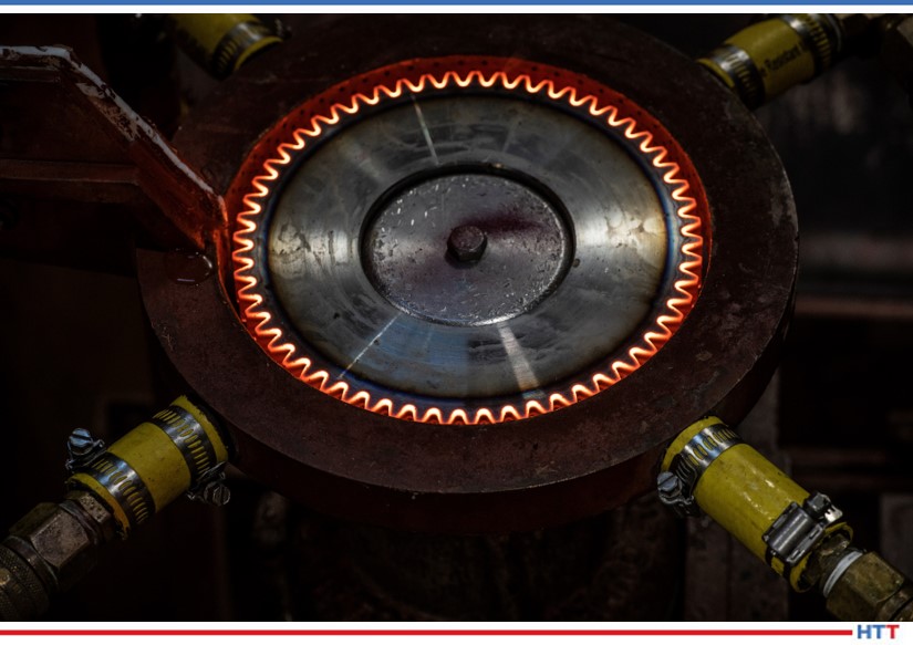
Gear Tooth Scan Inductor

Manufacturing inductor coils is a skill that takes years to develop and several more to master. These tools can be made from copper tubing utilizing fabrication techniques with the use of bending fixtures and forming dies. Most tools today are machined from solid, raw materials often with complex geometries. To ensure quality and consistency, 5-axis CNC machining is often used. Thirty to forty percent silver braze should be used for joining the inductor coil components and sealing water-cooling passages. Designs should avoid sharp corners and provide smooth transitions for optimal current flow and minimal stress risers. Computer-solid models, engineering drawings, and process forms following ISO 9001:2015 certified standards guarantee a quality manufactured induction coil.

Ring Bearing Inductor

Inductor coils are precision handmade tools and should be treated as such. Inductor coils should be supplied in a heavy-duty case with packing materials to provide the proper support and protection during shipping and storage. Identification should be clearly marked on the case. Many cases are lockable as theft may be a concern. When inductor coils are removed from service, they should be cleaned with soap and water using a Scotch-BriteTM cleaning pad. Steel wool and steel bristle brushes should be avoided as the steel can imbed into the copper and may cause more harm than good. Once the inductor is cleaned, it should be closely evaluated for signs of wear or damage. If there are any signs of wear or damage, it should be sent out for maintenance or repair so it will be ready for the next use. After tools are cleaned and evaluated, cooling passages should be blown out with air and the inductor should be dry before sealed in the case and put into inventory. Notes and pertinent data related to the inductor can also be stored with it such as the number of parts processed, any modifications made to the inductor coil, and recorded setup data.

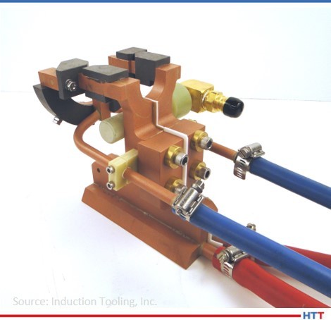
All of what was stated above about design and manufacture of inductor coils also applies to bus bars and quick-change adapters. These devices are used between the workstation and the inductor coil to bridge the gap closer to the workpiece. Originally developed for the automotive industry, quick-change adapters can drastically reduce changeover time, often without the use of hand tools. Since these devices are typically kept on the machine for long periods of time, it is important to check the condition and perform maintenance when needed. Scheduled maintenance of removal and cleaning of these devices will exceedingly increase their life. As with inductor coils, soap, water and a Scotch-BriteTM cleaning pad is all that is needed for these items; steel wool and steel bristle brushes should be avoided.

Multi-Turn O.D. Scan & Quench

When installing bus bars, adapters, and inductor coils with a bolted contact, it is extremely important to make sure that each of the mating surfaces are clean and free from debris. When dirt accumulates or ferrous debris is contained between the contacts, severe arcing and melting can occur.

It is also very important to use proper fasteners. For correctly fastening contact surfaces, 300 series stainless steel bolts with heavy brass washers are preferred. The heavy brass washers help distribute the load evenly and help prevent damaging the copper. The bolt threads should be inspected for wear and replaced new if there is any sign of wear or damage. It is also very important to verify that the length of the bolts will properly clamp without bottoming out before tightened. The recommended torque procedure for 3/8-16 stainless steel bolts is to tighten each bolt twice at 35 to 40-foot pounds. Special "break-away" bolts are available that are designed to fail beneath the washer if they are over tightened. This prevents damage to the threaded insert inside the copper contact. The remainder of the bolt can then be removed with pliers. This is much easier and less expensive than having to repair a bus bar contact or workstation transformer.

O.D. Scan with Quench

The workstation contacts, bus bars, adapters, and inductor coils are all electrical components that when energized are a live circuit, often with high power. The inductor coil produces a strong magnetic field used to heat the workpiece. There are also stray magnetic fields in the surrounding area. It is very important that everything in the surrounding area of these components be non-ferrous to prevent them from heating up. Something as simple as a steel hose clamp in close proximity to the magnetic field could heat up, causing a hose to melt, or a hose to come off, preventing water cooling and severely damaging the induction tooling or the induction machine. Steel fittings can rust and contaminate a water system very rapidly, choking the water flow internally and causing premature failure from low water flow. Any support structure to the induction tooling components should be a quality non-porous insulating material. Non-porous materials prevent liquid and contaminates from being absorbed and ultimately may cause a short circuit.

Proper water cooling is essential to the performance and longevity of tooling components. Both the induction power supply components and induction tooling components need to be properly cooled. Most power supply manufactures have a closed loop cooling system requiring deionized or distilled water. Most power supply manufacturers require that the cooling water temperature be maintained from 80 to 90 degrees Fahrenheit to prevent condensation inside the cabinet and on the circuitry. For cooling the inductor coil, bus bars, and adapters, deionized or distilled water is not necessary. Cooling water for these induction tooling components is best to be kept below 70 degrees Fahrenheit. This may require a separate cooling supply. Through laboratory experimentation and real-world production trials, it has been proven that lower cooling water temperatures can drastically increase the life of these components, especially in high volume, high power, short cycle applications.

The internal water-cooling passages of the inductor coil can play a significant factor in performance and longevity. Each inductor design should focus on maximizing water flow while minimizing sharp transitions.

The cooling water supply should come from a clean water source with a filtration unit of 25 microns placed just before it enters the induction tooling components. This guarantees that contaminates are filtered out, which may otherwise cause a low-flow or no-flow condition.

Quality non-ferrous fittings should be properly sized and configured to ensure the hoses are attached correctly to the induction tooling. It is very common to see 3/8" quick-change fittings used for cooling lines and 1/2" or 3/4" quick-change fittings used for quench lines. Using quick-change sockets for supply lines and quick-change plugs for return lines ensures the proper connections are made every time. Color-coding the hoses also helps in identifying water lines. It is very common to see blue hose for supply lines, red hose for return lines, and black hose for quench lines.

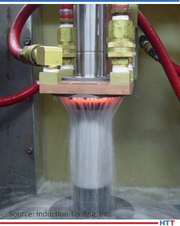
Single Shot Stem Inductor

Some inductor coils can be very small, having very limited water-cooling passages due to physical space. With these small inductors, it is even more important to have proper water cooling. In these situations, the use of a high-pressure booster pump may become necessary. These pumps can ensure cooling water continues to flow through these tight passages. Positive displacement pumps can also overcome steam pockets and help prevent vapor locks.

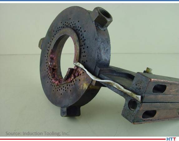
Problems with a cooling system can be detrimental to the performance and longevity of induction tooling components. Contamination in the cooling system can lead to low water flow. Problems with the water pump can also cause a low water flow condition. Then, low water flow can cause a steam vapor lock in the inductor coil leading to a rupture at a braze joint, a rupture through the tubing in a fabricated inductor coil, or a breach in the copper exposing the cooling chamber. Low water flow can also cause laminar flow internally which leads to thermal failure, resulting in exposed surface cracks through to the cooling chamber. Low water flow is sometimes identified by darkening of copper with purple color tones on the cooling return side of the inductor coil.

Wheel Bearing Single Shot Hardening

Induction tooling components cannot survive without water cooling. Symptoms include darkening of copper with purple color tones, melted copper, and catastrophic failure. Catastrophic failures caused by a no-water condition cannot be patched and require a major rebuild or replacement. It is a wise investment to have a flow indicator on the machine that prevents operation if there is no water flow or a low water flow condition.

All of what is stated earlier about the design and manufacture of inductor coils, bus bars, and adapters can also apply to quenches. These devices are used to evenly cool the part after heating to transform the structure consistently. Let’s discuss some of the important details in a quench system such as their design, fitting and hose requirements as well as pumps, filtration, and maintenance.

Quenches should be designed to provide a sufficient amount of quench to fully transform the metallurgical structure as specified. The quench pattern should be a uniform array of holes to quench the part at a proper impingement angle. The volume of water required should be matched with a supply having an inlet to outlet ratio not to exceed 1 in: 2 out. Hoses should be specified non-conductive and rated to meet or exceed supplied water pressure. Fittings should be high quality, non-ferrous without auto shutoffs, which can hinder quenching action and tend to clog more often.

Quenches can be a component that is kept on the machine for long periods of time. It is important to check the condition of these devices and perform routine maintenance. Scheduled maintenance of removal and cleaning these devices will exceedingly increase their life. Soap, water and a Scotch-BriteTM cleaning pad works well, and again, steel wool and steel bristle brushes should be avoided. Having a quench designed with bolted removable quench plates allows easy clean out.

Quench water needs to be filtered and contaminates kept at a minimum to improve performance and increase longevity of induction tooling components. A typical quench filter consists of a stainless-steel filter housing and a 100-microns bag filter. It is also very important to have a system for magnetic particle removal. Magnetic rod filters are available in many configurations, some that install inside the filter housing with the bag filter. Automatic separators are also often used. A low-cost alternative is to install a rubber coated magnet in the quench tank. In a non-ferrous tank, it can simply be dropped to the bottom. In a ferrous tank, it must be suspended to prevent the tank itself from becoming magnetized. All these methods can work, but only if they are properly maintained. A solid preventative maintenance schedule for these filters is essential.

Low Water Flow Failure

When filters are not used or maintained, tooling repairs are required more frequently. Common contaminates found inside quenches include oil dry, metal chips, and chewing tabaco. We see inductor coils come in for rebuild with a heavy patina of dirty, crusty contaminates. These contaminates are commonly a buildup of magnetic particles attracted by the magnetic field generated by the inductor coil. This patina accumulates and can create a short circuit, damaging the inductor coil.

To summarize, contamination is by far the most common cause of induction tooling failures. Water cooling is essential for longevity of induction tooling. Maintenance is essential for the performance of induction tooling. High quality, well-designed, robust induction tooling should be used for best results and consistency. Analyze induction tooling failures when they occur. Troubleshoot induction tooling rebuilds for possible machine issues. Look for methods of improvement with each opportunity. In closing, the best way to improve the performance and longevity of induction tooling components is to have open and frequent lines of communication with your tooling vendor.

About the Author: David Lynch is vice president of engineering at Induction Tooling, Inc. with 36 years of experience and is also the Deputy of the ISO quality system. He has created and developed the system and templates being used today for creating and tracking engineering drawings, job history, rate tracking, and job performance. David holds several design patents, has authored several published articles, and has often presented at technical sessions. He enjoys working closely with customers to develop valued solutions across a wide range of induction heating applications from initial design concepts to implementation, customer support and troubleshooting.

For more information, Contact David at dlynch@inductiontooling.com.

How to Improve the Performance and Longevity of Induction Tooling Components Read More »

Moving Beyond Combustion Safety

op-edIn this month’s column, John Clarke will expand his discussion beyond combustion safety to include the economic issues that are concerns to all equipment owners and operators.

This column appeared in Heat Treat Today’s 2021 Induction May print edition.

 John Clarke is the technical director at Helios Electric Corporation and is writing about combustion related topics throughout 2021 for Heat Treat Today.


John B. Clarke
Technical Director
Helios Electric Corporation
Source: Helios Electric Corporation

The furnace's or oven’s burner management system (BMS) and its associated components are all that stand between us and an incident. The severity of these incidents ranges from the very expensive — a damaged furnace or oven — to the tragic — loss of a human life. It is a testament to the good work of hundreds of people that combustion system explosions are so rare. That said, the risk to life and property mandates that we revisit this subject frequently, and the risk to profitability dictates we expand our consideration beyond safety to include uptime and quality, as well.

National Fire Protection Association Standard 86 (NFPA 86), or “Standard for Ovens and Furnaces,” provides a standard that is the most common guide to the application of combustion components used in the US. This excellent prescriptive standard reflects the common thinking of people with hundreds of years of combined experience; but it still requires expertise to properly interpret and apply its requirements. It is important to not only understand what component must be provided, but also why.

NFPA 86 is used as a guide for the design of your BMS which includes the various control components to properly monitor the startup and operation of the burner. NFPA 86 also applies to the fuel train, constructed of components that regulate the flow of fuel and air and includes blowers, regulators, valves, filters, and sensors. What BMS and fuel train safety system issues should most concern an end user? An end user must know what it really means when your system is stamped “NFPA 86 Compliant.” To paraphrase Clint Eastwood: The end user needs to know their system’s limitations.

The NFPA 86 standard has been developed to protect life and property, but not production and profits. It is also a prescriptive standard, providing specific guidance to what components need to be applied and in what order. The shortcoming of a prescriptive code is that it must be mostly generic, that is, it applies to types or classes of equipment as opposed to specific applications. Given the variety of burner applications used in industry, it would be impractical to specify every component, order, and wiring for every conceivable process heating application.

Why is this a concern for end users? A specific application may have unforeseen risks or are out of the scope of NFPA 86 . Critical failure modes may be indirectly associated with a burner failure. For example, loss of a process air flow may allow a heat exchanger to overheat before a high temperature limit instrument detects the temperature rise. In this case, the process air flow must be monitored, and the flow or pressure switch monitoring the air flow must be added to the interlock string. This way, the burner will shut off as soon as the air flow failure is detected and not wait for the heat exchanger’s temperature to rise to an unsafe temperature. Another reason to “exceed” the code is that often ovens or furnaces are one element in a much larger manufacturing system. An example would be a continuous paint line, where a failure of the curing oven might shut down an entire facility.

What should an end user do? Ensure the system provided meets the standards and codes, NFPA 86, the Fuel Gas Code (NFPA 54), NEC, etc. This level of compliance is the minimum – and is often not the optimal. Additionally, invite the OEM who built the system to apply their experience and exceed the standards if it provides a more robust system. It may cost a few dollars up front, but it will be pennies when compared to the cost of an incident or, in many cases, an outage.

Encourage your supplier to apply a recognized process to the system review, perhaps a failure mode effects analysis (FMEA) and factor in not only the cost of an incident, but the cost of lost production or quality rejects as well. Consider an independent third-party review – it never hurts to get a second opinion. Review the cost of redundancy, be it online or near online . What is the cost of a second flame rod and flame safeguard when compared to the value of four hours of production?

Next, review the steps to service the system. Look at the mean time to replace (MTTR) a failed component. Has the system been designed to be easily serviced? Are there pipe unions on either side of all critical valves? Where are the spare parts located? What skill trades are required to make the repair? Is post replacement calibration or testing required? And if so, has it been documented?

Ask if the BMS provides a clear indication of the reason for a shutdown. The interlock string, a logical series wiring of critical components where any one component indicating a fault will disable the combustion system, should be monitored in a way where the “first out” or component that will shut down the system, is clearly identified.

Lastly, it is the end user’s responsibility for periodic inspections and equipment maintenance. NFPA 86 prescribes that the BMS and fuel train components are inspected per the manufacturer’s recommendation, but at least once a year.

The annual inspection is a critical step for safe operation but is viewed by many end users as simply a cost. Add to this the relative reliability of most components and we are presented with the ironic risk that maintenance personnel may take short cuts during the periodic inspection. One such person may say, “I always check the low gas pressure switches and they always pass, so I thought, what would it hurt if I skipped the test this year?”

For a more robust inspection, consider adding more value to the process. Combine the safety inspection with an extensive equipment calibration and service: Replace the filters, change the thermocouples, calibrate the control instruments, tune the burner, check the fuel-to-air ratio of the burner, and inspect the BMS components. This adds value to the process and makes it more palatable for the maintenance department.

When the cost of downtime of a key piece of equipment is high, practice the repair, at least on paper. However, if a failed burner shuts down an automotive assembly line, isn’t it worth the time to run actual drills?

In general, most burner trips are the result of a failed sensor, a UV scanner, dirty flame rod, an open thermocouple, or the vibration from an unbalanced fan tripping a pressure switch. In other words, when this type of trip occurs, the greatest cost is lost production, followed by the labor to diagnose the problem and then the cost to replace the component. Generally, the purchase price of the component is far less than the other costs associated with the system trip. Do not be penny wise and pound foolish. Spare parts are a pretty good investment.

If you need the heat from a burner to make your product, it makes sense to not only consider safety, but also plan reduced downtime as well. In the coming articles, we will examine these issues in greater detail, so stay tuned.


References:
[1] https://www.nfpa.org/codes-and-standards/all-codes-and-standards/list-of-codes-and-standards/detail?code=86


About the Author:

John Clarke, with over 30 years in the heat processing area, is currently the technical director of Helios Corporation. John’s work includes system efficiency analysis, burner design as well as burner management systems. John was a former president of the Industrial Heating Equipment Association and vice president at Maxon Corporation.

Moving Beyond Combustion Safety Read More »

Red Hot Basics: The World of Induction

Source: Inductoheat.com

In preparation for Heat Treat Today's May Induction magazine, here is a best of the web to end your week on.

How do they do it? What happens to metals when they are being induction heated? If you've had experience with heat treating using induction, how does it compare to other forms of heat treatment? This helpful article runs down the basics of induction and includes a video with different phases of the process. Check it out!

"As current flows through a medium, there will be some resistance to the movement of the electrons. This resistance shows up as heat (The Joule Heating Effect). Materials that are more resistant to the flow of electrons will give off more heat as current flows through them, but it is certainly possible to heat highly conductive materials (for example, copper) using an induced current."

Read more: "What is Induction Heating?"

Red Hot Basics: The World of Induction Read More »

8 Heat Treaters Improve Processes with Simulation Software

Source: CENOS

Heat Treat Today brings you this best of the web content to highlight how 8 companies have been using simulation in their heat treat processes. In the article, the companies attest to saved time and costs as well as the benefits of visualizing accurate results. Check it out!

An excerpt:

[blockquote author=”CENOS” style=”1″]Old coil design failed and started leaking after 20,000 shots, while the redesigned coil is still running after 122,000 shots – more than five-fold improvement of the coil lifetime. By summing all of the benefits of the simulation software adoption in the engineering routine of the plant, Kevin got a 9% increase of the overall equipment efficiency (OEE).[/blockquote]

Read More: “8 Stories on How Computer Simulation Helped Companies to Improve Induction Heating in 2020”


All images provided by CENOS.

8 Heat Treaters Improve Processes with Simulation Software Read More »

Induction Hardening: Strengthening the Automotive Industry into the Future

Kyle Hummel, Project Engineer, Contour Hardening

Induction hardening has played a critical role for decades in heat treating. In this Heat Treat Today Technical Tuesday feature, Kyle Hummel, Professional Engineer at Contour Hardening, shares his engineering insights on the necessity of induction-hardened components for automotive powertrains. As a manufacturer with in-house induction hardening or a commercial heat treater, learn about viable considerations in moving forward with your induction hardening process.

This article appeared in the edition June 2020 edition of Heat Treat Today's Automotive Heat Treating magazine.


Induction hardening has played a crucial role in the automotive industry for many decades and is poised to continue that role into the future as the industry prepares for the inevitable shift to electric vehicles. Over the past 15 years, the emphasis on fuel economy, increased quality standards, and the emergence of other heat treat methods have drastically altered the design and necessity of induction-hardened components for automotive powertrains.

Transformation of Component Design

Increased residual compressive stress, minimal distortion, and the ability to selectively harden portions of a component are some of the main characteristics that have made induction hardening a popular choice for gears and shafts in the automotive industry. From the early 1980s to the 2000s the number of gears being hardened via induction was tremendous. The strength requirements for gears in four- and six-speed transmissions demanded the added compressive stress coupled with low distortion for noise reduction that induction hardening provides. As transmissions have increased to eight, nine, and 10 speeds over the past 10 years, the peak loading conditions of the gears has decreased, opening up the availability of other heat treat options. Low distortion processes such as nitriding and ferritic nitrocarburizing have now been successfully utilized in these gear applications because the gears do not require the high amounts of residual compressive stress. As the volume of these gears has decreased, other highly complex and high-volume components still remain great candidates for induction hardening.

Constant velocity joints (CVJ) rely on induction hardening and should remain relatively unaffected by the transition to electric vehicles. CVJs are typically designed for individual vehicle platforms rather than transmission platforms which can encompass a number of different vehicles. This leads to a greater variety of different part numbers to be hardened, and most CVJs typically require hardening in more than one region. These aspects require the need for specialized equipment to harden the CVJs that are difficult to adapt to other types of components.

Automated Hardening of CVJs

In addition to CVJs, the advancements in powder metal (PM) capabilities in the past decade have also created a surge in the number of PM components that require induction. PM sprockets and other uniquely shaped components that require high wear resistance are paired with induction hardening to replace traditionally machined components.

As the technology in PM has improved, the ability to achieve full density at varying depths below the surface has recently led to the production of internal gears that can be induction hardened for added strength and wear properties. Other technically complex components such as sliding panels, stator shafts, and input shafts continue to utilize induction to increase strength and wear resistance in specific areas. As engineers continue to push the design limits of components, specialized induction hardening equipment with precision control, higher power, and shorter heat times is required to successfully develop a robust process.

Unique Technical Challenges

Induction Hardening Machine (both figures)

The technical challenges for induction heat treaters have increased with the added complexity of these components and the emphasis on several quality standards. It requires an entire team of engineers to provide input with coil design, process development, and adherence to quality standards. The days of having a print specification simply list a visual case depth and a surface hardness are a distant memory. Specifications now commonly require effective case depths at multiple locations, microstructure evaluations, and hardness and dimensional inspections. CVJs in particular can have over 35 metallurgical inspection points and over 25-dimensional inspection points. The component complexity has also led to the need for increased crack inspection. Sharp corners, thin walls, lubrication holes, and the use of higher carbon steels have led many parts to require nearly 100 percent inspection for cracks.

Along with the print specifications, heat treaters must also comply with the growing number of technical standards required to be an approved automotive supplier. IATF 16949 Quality Management System, AIAG’s Heat Treat Assessment (CQI-9), ASTM standards, and customer specific requirements can create a vast network of conditions that must be examined and constantly monitored to ensure compliance. Although these added requirements can be an inconvenience, the quality of parts being produced has significantly improved and that ultimately leads to safer and more reliable vehicles for the customer.

Adapting to the Future

Unfortunately, the technical challenges and increased quality requirements of automotive parts do not always come with higher margins. With the competition in Mexico and Asia, U.S. manufacturers with their own in-house heat treating and commercial heat treaters must continue to find ways to remain competitive. The volatility of OEM volume predictions and platform start and end dates requires manufacturers and heat treaters to be dynamic in capacity considerations. With induction hardening, having excess capacity at a variety of different frequencies and power capabilities can be crucial to landing the next job. Automotive work can frequently come in due to unplanned downtime at a competitor, or on a customer’s own heat treat line. If your organization does not have the ability to produce test samples almost immediately, that opportunity for valuable work will be missed. Having the knowledge and equipment to understand and provide testing for dimensions is another key to offering value to automotive customers. The ability to test parts green and immediately after hardening can drastically reduce scrap and rework and can be a crucial selling point to customers.

The piece by piece processing of induction hardening is suited well for automation and the benefits reach beyond simply reducing labor costs. The reduction in tooling changeovers not only reduces wasted time, it also improves the quality and consistency of the product. With tight dimensional tolerances on final parts, slight variations in heat treat patterns can be eliminated by dedicating and automating a heat treat line. The ROI for automating a cell, including temper and rust preventative application can be as little as six months with the added bonus of supplying a more consistent part to the customer.

High-volume, complex components provide special challenges for induction heating.

The modern induction hardening facility should be moving to automate not only the production itself, but also the inspections, factory information systems, and ERP systems. Inspections such as eddy current can be automated to reliably inspect 100 percent for proper hardening and even crack detection. Automated microhardness equipment can save lab technicians hours of valuable time they would have spent waiting at the tester. These technologies, when used appropriately, can result in more efficient processes that produce higher quality parts at competitive prices.

Although the landscape of the automotive industry in the next 15 years is as exciting as it is uncertain, induction hardening will continue to be a vital process that is utilized into the future. The changes over the past 15 years have produced more complex components with stricter requirements that must be processed with greater efficiency. Induction hardening suppliers must remain focused on keeping pace with the developments in technology that continue to improve the heat treat industry as a whole in order to remain relevant and be a value-added process for automotive customers.


About the author: Kyle Hummel is a licensed Professional Engineer who has worked for Contour Hardening for 14 years as a metallurgical engineer focusing on process development and quality improvement.

For more information, contact Kyle at khummel@contourhardening.com or (317) 876-1530 ext. 333.


Induction Hardening: Strengthening the Automotive Industry into the Future Read More »

Replacing Heat Treating Induction Coils Just Got Better

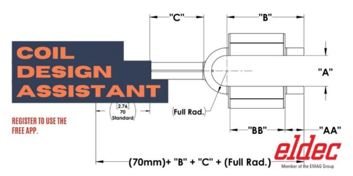
Cut down administrative time, streamline ordering processes, reorder induction coils you can count on. All of these goals sound great, and that's just what eldec LLC.'s new app sets out to do. In this Heat Treat Today Original Content article, eldec Sales Engineer, Greg Holland, shares how their new app, the Coil Design Assistant (CDA) helps heat treaters to efficiently design and order induction coils.


This past month, eldec LLC. released a free app called Coil Design Assistant (CDA) which is intended to streamline the ordering process of induction coils. Specifically designed for cases when customers know what they want, the app will "convey that information to us quickly," says Greg Holland, sales engineer at eldec LLC., "to reduce the time to quote, fabricate and deliver to the job site."

eldec Coil Design Assistant (photo source: inductionheatingexperts.com)

How the app works is by first submitting information about the induction coil. If a customer has an existing eldec coil to replace, the submission only requires the serial number. If the customer wants to replace their coil from a non-eldec coil, or if they want to customize a coil to optimize performance based on part geometry, the CDA can still be used to configure a basic coil design to specifications. This app will then make future order modifications or extensions more streamlined. Even in situations when a customer has forgotten the serial number, Holland says the app helps "to expedite replacement" when describing a homemade coil.

Screenshot of the CDA interface (photo source: eldec LLC.)

In fact, like more conventional modes of requesting, all requests made through the app are handled by the eldec application team prior to giving a quotation, "and approval drawings are provided prior to fabrication." So, the team is on hand both to work with customers on the coil design if the customer desires, and for nuanced questions that arise in the review process regarding topics like current, frequency, or overall process.

The big time saver on this is the interpretation from 2D to 3D imaging. Holland states: "Often, a sketch does not capture the third dimension involved in most, if not all, induction applications. The app allows the coil dimensions to be quickly communicated to eldec for even faster quotations and in a format that our engineering team can use to quickly turn around a 3-D approval drawing for customer review, often within a day or two from order."

While the app works best with eldec machines, many other machine builders have adopted the eldec standard 50 mm foot, making the CDA "valuable for use with all inductor designs." Further, Holland comments, if the power supply, for instance, has a mounting foot which is designed differently than the eldec standard design, the CDA features automatic prompting to a discussion platform with an application team expert.

The app will not fully replace the more complex orders and is selective in the number of categories that it has available, so eldec encourages people with complex design needs to contact the sales team directly to talk with a designer.

Holland shares that although there is no fool-proof timeline for tracking coil life, here are a few things to bear in mind:

Straight Assembly (photo source: eldec LLC.)


  1. Check ceramic coating (if included on the coil) for chipping/flaking and wear to the point of bare copper being exposed.
  2. Check concentrators (laminations or ferrotron) for discoloration, as this is a sign of overheating. Also, check the concentrators for physical damage, cracks, and major chips (minor chips should not significantly affect functionality)
  3. Check the bottom of the coil foot for spots where the coil may have arced to the coax transformer. If there are arc spots, this is an indication that the coil is not tight enough on the coax; loose coils can cause multiple issues that are not limited to just coil failure.
  4. Check for excessive discoloration of the coil leads and gussets. This could be a sign of overheating.
  5. Check for badly warped or bent coil leads as this is an indication that the operator is putting excessive stresses on the coils during operation. Too much stress on the coils can lead to extra wear of the base copper and any brazed joints in the coil construction.
  6. Check white Teflon (between coil leads) for signs of melting. Again, this would be an indication of overheating on that particular coil.
  7. Check the mica on the heating face for signs of excessive wear and replace as needed.


Proper coil design is a critical aspect in the heat treating process. As Holland indicates, the best coil is customized to the specific, intended process. Shapes, features, and coupling distance must be taken account of to evenly and effectively distribute heat and increase process efficiency. Further, he says, "With a more efficient process and coil design, energy usage decreases, workpart quality increases, as does coil life, and overall costs decrease."

eldec team (photo source: inductionheatingexperts.com)


Replacing Heat Treating Induction Coils Just Got Better Read More »

Heat Treat Tips: Induction Heating

One of the great benefits of a community of heat treaters is the opportunity to challenge old habits and look at new ways of doing things. Heat Treat Today’s 101 Heat Treat Tips is another opportunity to learn the tips, tricks, and hacks shared by some of the industry’s foremost experts.

For Heat Treat Today’s latest round of 101 Heat Treat Tipsclick here for the digital edition of the 2019 Heat Treat Today fall issue (also featuring the popular 40 Under 40).

Today’s tips come to us from Rob Medeira and Florie Grant of Inductoheat, covering Induction Heating. This includes advice about correcting irregular part distortion and finding solutions to cracked parts.

If you have a heat treat-related tip that would benefit your industry colleagues, you can submit your tip(s) to anastasia@heattreattoday.com  or editor@heattreattoday.com.


Heat Treat Tip #13

Correcting Irregular Part Distortion

(source: Inductoheat)

Situation: Part is distorting irregularly after induction heat processing
Solution:
1. Check quench concentration, flow, & pressure.
2. Make sure there is proper quench uniformity.
3. Check TIR of the spindles and part holding fixtures
4. Check to ensure the part dimensions are accurate & center drills are on center.
5. Check part nest clearance when the part is cold.
6. Check to make sure the heating time is not too long.

HINTS:
· Check the part holding fixtures and spindles to ensure proper positioning.
· Some processes use a negative quench delay, quench on before heating stops, typically 0.05-0.3 seconds to improve TIR of the part.
· The part nest should not fit snug when the part is col – it will grow during the heating & warp the part.
· If the spline area has distortion or the “Go” gage is tight, try a quench delay of 0.2 to 0.4 seconds.


Heat Treat Tip #14

Cracked Parts?

(source: Inductoheat)

Situation : Cracked Parts
Solution:
1. Check parts positioning.
2. Make sure there are no unexpected hot spots; lack of rotation may be the cause.
3. Check for excessive grain growth around the crack surface area.
4. Check if quench condition is out of spec.
5. Check surface finish of part prior to hardening.
6. Apply temper ASAP.
7. Confirm & inspect steel conditions.

HINTS:
· If the part has excessive grain growth, that may lead to cracking.
· If cracking appears around hole area, then the proper chamfering might help.
· Parts out of higher carbon steels (0.55%C or higher) use higher quenching concentration & avoid surface overheating.


Heat Treat Tips: Induction Heating Read More »

Dr. Valery Rudnev on Equipment Selection for Induction Hardening: Single-Shot Hardening, Part 3

This article continues the ongoing discussion on Equipment Selection for Induction Hardening by Dr. Valery Rudnev, FASM, IFHTSE Fellow. Six previous installments in Dr. Rudnev’s series on equipment selection addressed selected aspects of scan hardening and continuous/progressive hardening systems. This post is the third in a discussion on equipment selection for one of four popular induction hardening techniques focusing on single-shot hardening systems.

Previous articles in the series on equipment selection for single-shot hardening are here (part 1) and here (part 2). To see the earlier articles in the Induction Hardening series at Heat Treat Today as well as other news about Dr. Rudnev, click here


Single-Shot Inductors for Non-Cylinder Parts

Single-shot inductors can be successfully used for hardening not only components of classical cylinder geometries but other geometries as well. This includes workpieces of general conical shapes, such as elliptic, parabolic, hyperbolic geometries—and the list can grow. As an example, Figure 1 shows induction surface-hardened ball joints (ball studs) and the single-shot inductors used to harden them. Ball studs are used in automotive, off-road, and agricultural machinery and can be different in shape and size (Compare images on the left in Figure 1 with images on the right.), requiring noticeably different hardness patterns.

Figure 1. Surface-hardened ball joints (ball studs) and single-shot inductors used for its hardening. (Courtesy of Inductoheat Inc., an Inductotherm Group company.)

In any attempt to scan harden workpieces with appreciable diameter changes, the scan coil must have a sufficient gap to clear the largest diameter. When scanning the section(s) of the workpiece with smaller diameters, an inductor-to-shaft air gap might be very large, resulting in low electrical efficiency and potentially exhibiting difficulties in load matching as well as in controlling the austenitizing pattern along the length of the part producing "cold" and "hot" spots. Additional difficulties may appear in controlling the hardness pattern in regions (e.g., near geometrical irregularities) where good control is most needed.

Thus, the substantially different workpiece-to-inductor electromagnetic coupling variations might not permit using classical multiturn solenoid coils or scan inductors. In contrast, single-shot inductors allow not only better electromagnetic coupling along the entire length of heat treated components (Figure 2) but also better address the geometrical irregularities of heat treated workpieces, producing the required hardness patterns at minimum process times with superior metallurgical quality.

Figure 2.  Single-shot inductors allow better electromagnetic coupling along the length of heat treated components properly addressing the geometrical complexity of the workpiece. (Courtesy of Inductoheat Inc., an Inductotherm Group company.)

As stated in Part 1 of this series, in contrast to scan hardening, a single-shot inductor can be contoured along the length of the part properly addressing the geometrical complexity of the workpiece. Furthermore, the use of flux concentrators helps drive the current into the desired areas and allows producing a well-defined hardness profile with minimum distortion. The trade-off here is that more finesse is required in the design stage to produce the properly profiled single-shot inductor at the lowest possible cost.¹ Errors are costly since these inductors are each custom made for a given part or application and modifications can be quite costly. Thus, computer modeling is a helpful assistant as an attempt to keep the development cost down and shorten the "learning curve".

Proper hardening of such components as output shafts, flanged shafts, planet carriers, yoke shafts, sun shafts, intermediate shafts, driveshafts, turbine shafts, and some others may require extensive copper profiling, making a single-shot hardening inductor a complex electromagnetic device.

Certain geometrical features such as flanges, diameter changes, bearing shoulders, grooves, undercuts, splines, etc., may distort the mag­netic field generated by an inductor, which, in turn, can cause tem­perature deviations, making it challenging to achieve certain hardness patterns.

For components containing fillets, it is often necessary to increase the heat intensity in the fillet region owing to the geometrical specifics. Also, the larger mass of metal in the proximity of the heated fillet and behind the region to be hardened produces a substantial thermal “cold sink” effect.¹ This draws heat from the fillet due to thermal conduction, which must be compensated for by generating additional heating energy in the fillet area.

Needed energy surplus can be achieved by narrowing the current-carrying face of the crossover segment of the single-shot inductor (Figure 3). Here is a simplified illustration of an impact of a copper profiling of the inductor’s heating face: if the current-carrying portion of the inductor heating face is reduced by 50 percent, there is a corresponding increase in current density. This will be accompanied by an increase of the eddy current density induced within the respective region. According to the Joule effect, doubling the induced eddy current density increases the induced power density roughly by a factor of four. Also, attaching a magnetic flux concentrator to certain areas of the hardening inductor further enhances the localized heat intensity.

Figure 3.  Longitudinal leg sections of single-shot indicators and their crossover segments can be profiled by relieving selected regions of the copper to accommodate workpiece geometrical features. Attaching a magnetic flux concentrator to certain areas of the inductor further enhances localized heat intensity. (From V. Rudnev, A. Goodwin, S. Fillip, W. West, J. Schwab, S. St. Pierre, Keys to long-lasting hardening inductors: Experience, materials, and precision, Adv. Mater. Processes, October 2015, pp. 48–52.)

When using a single-shot inductor, it is particularly important that the workpiece is properly located in the heating position because seemingly minor dislocations may noticeably affect the heat treat pattern and metallurgical quality of hardened parts.

Traditionally designed single-shot inductors may exhibit high process sensitivity that is associated with the electromagnetic proximity effect.¹ A change in positioning of the workpiece inside the single-shot inductor attributed to excessive bearing wear of the centers, improper machining of the centers and fixtures, incorrect part loading, and other factors may produce a correspondent appreciable variation in the hardness pattern (particularly within the fillet region, undercut areas, and the part’s end zone). A reduced hardness case depth and the formation of unwanted microstructural products associated with incomplete phase transformation may be the result of that. Magnitude and distribution of transient and residual stresses might also be altered. Thus, attention should be paid to part’s reliable positioning during heating and quenching cycles.

As can be concluded, there are good reasons for using single-shot hardening, scan hardening, or continuous/progressing hardening approaches in induction hardening applications. The decision must be well thought out based on many factors such as geometry specifics, product quality, production rate, design proficiency, limitations of available equipment, reliability requirements, cost considerations, and some other factors.

The next installment of this series, Dr. Valery Rudnev on .  . . , will continue the discussion on design features of induction single-shot hardening systems.


References

  1. V.Rudnev, D.Loveless, R.Cook, Handbook of Induction Heating, 2nd Edition, CRC Press, 2017.
  2. V.Rudnev, "Dr. Valery Rudnev on . . . Equipment Selection for Induction Hardening: Single-Shot Hardening, Part 1", Heat Treat Today, July 9, 2019.
  3. V.Rudnev, A.Goodwin, S.Fillip, W.West, J.Schwab, S.St.Pierre, "Keys to long-lasting hardening inductors: Experience, materials, and precision", Adv. Mater. Processes, October 2015, pp. 48–52.

Dr. Valery Rudnev on Equipment Selection for Induction Hardening: Single-Shot Hardening, Part 3 Read More »

Dr. Valery Rudnev on Equipment Selection for Induction Hardening: Single-Shot Hardening, Part 2

This article continues the ongoing discussion on Equipment Selection for Induction Hardening by Dr. Valery Rudnev, FASM, IFHTSE Fellow. Six previous installments in Dr. Rudnev’s series on equipment selection addressed selected aspects of scan hardening and continuous/progressive hardening systems. This post is the second in a discussion on equipment selection for one of four popular induction hardening techniques focusing on single-shot hardening systems.

The first part on equipment selection for single-shot hardening is here; the third part is here. To see the earlier articles in the Induction Hardening series at Heat Treat Today as well as other news about Dr. Rudnev, click here


Traditional Designs of Single-Shot Inductors

Figure 1 shows a typical shaft-like component (Figure 1,top-left) suitable for a single-shot hardening inductor, as well as a variety of traditionally designed single-shot inductors for surface hardening shaft-like workpieces. Sometimes, these inductors are also referred to as channel inductors.

A conventional single-shot inductor consists of two legs and two crossover segments, also known as bridges, “horseshoes,” or half-loops [1]. The induced eddy currents under the legs primarily flow along the length of the part (longitudinally/axially) with the exception of the regions of the workpiece located under the crossover segments where the flow of the eddy current is half circumferential. Unlike scanning inductors, traditional designs of single-shot inductors can be quite complicated.

Figure 1. A typical shaft-like component (top-left image) suitable for a single-shot hardening and a variety of traditionally designed single-shot inductors for surface hardening shaft-like workpieces (Courtesy of Inductoheat Inc., an Inductotherm Group company)

With a predominantly longitudinal eddy current flow, the heat uniformity in the diameter change areas of the stepped shafts is dramatically improved and the tendency of corners and shoulders to be overheated is reduced significantly compared to applying a single-turn or multi-turn solenoid coils commonly used in scan hardening and continuous/progressive hardening.

Because the copper of single-shot inductors does not completely encircle the entire region required to be heated, rotation must be used to create a sufficiently uniform austenitized surface layer along the workpiece perimeter. Upon quenching, a sufficiently uniform hardness case depth along the circumference of the part will be produced. For single-shot inductors, the rotation speed usually ranges from 120 to 500 rpm.

Different types of magnetic flux concentrators (also called flux intensifiers, flux controllers, flux diverters, magnetic shunts, etc.) complement the copper profiling of an inductor, helping to achieve the required hardness pattern. Flux concentrators may provide several considerable benefits when applied in single-shot inductors. This includes an increase of coil electrical efficiency, a noticeable reduction of coil current, and a significant reduction of the external magnetic field exposure.

As an example, Figure 2 shows a transverse cross-section of a single-shot inductor and a straight shaft. Computer-modeled electromagnetic field distribution of a bare inductor (Figure 2, left) compared to an inductor with a U-shaped flux concentrator (Figure 2, right) is shown. Note that the magnitude of magnetic field intensity on both images is different. The use of U-shaped magnetic flux concentrators in single-shot hardening applications typically results in a 16% to 27% coil current reduction compared to using a bare inductor while having a similar heating effect. A reduction of the external magnetic field exposure while applying flux concentrator is even more dramatic (Figure 2, right).

Figure 2.  Computer-modeled EMF distribution in the transverse cross-section of a bare inductor (left) compared to an inductor with U-shaped flux concentrator (right). Note: the scale of magnetic field intensity on both images is different [1].
Different applications may call for various materials used to fabricate magnetic flux concentrators including stacks of silicon-steel laminations, pure ferrites, and various proprietary multiphase composites. The selection of a particular material depends on a number of factors, including the following [1]:

  • applied frequency, power density, and duty cycle;
  • operating temperature and ability to be cooled;
  • geometries of workpiece and inductor;
  • machinability, formability, structural homogeneity, and integrity;
  • an ability to withstand an aggressive working environment resisting chemical attack by quenchants and corrosion;
  • brittleness, density, and ability to withstand occasional impact force;
  • ease of installation and removal, available space for installation, and so on.

It should be noted that, though in most single-shot hardening applications flux concentrators will improve efficiency, there are other cases where no improvement will be recorded, or efficiency may even drop. A detailed discussion regarding the subtleties of using magnetic flux concentrators is provided in [See References 1, 2.].

Sufficient rotation is critical when using any single-shot inductor design. As an example, Figure 3 shows the sketch of a single-shot induction hardening system.

Figure 3.  Sketch of single-shot induction hardening of an axle shaft. Note: The right half of this induction system is computer-modeled in Fig. 4 [3].
Taking advantage of symmetry, only the right side of such a system was modeled using finite-element analysis. Figure 4 shows the result of computer simulation of initial, interim, and final heating stages, taking into consideration the shaft rotation. Insufficient part rotation resulted in a non-uniform temperature distribution along the shaft perimeter (Figure 4, left). Proper shaft rotation results in a sufficiently uniform temperature pattern (Figure 4, right).

Figure 4.  Results of numerical simulation of heating an axle shaft by using a single-shot inductor [3].
There should be at least eight full rotations per heat cycle (preferably more than 12 rotations), depending on the size of the workpiece and the design specifics of the inductor, though, as always in life, there are some exceptions. Shorter heating times and narrower coil copper heating faces require faster rotation during the austenitization cycle.

An appropriate inductor design with a closely controlled and monitored rotation speed will produce a hardness pattern with minimum circumferential and longitudinal temperature deviations, which will result in sufficiently uniform hardness patterns (Figure 5, left four images). Failure to ensure proper rotation as well as the use of worn centers (lacking grabbing force resulting in slippage and excessive part wobbling) could lead to an unacceptable heat non-uniformity, severe local overheating, and even melting (Figure 5, right). Manufacturers of induction equipment such as Inductoheat have developed various proprietary tools, holders, fixtures, and monitoring devices to ensure proper rotation and high quality of single-shot hardened parts.

Figure 5.  Inductor design with closely controlled rotation speed will produce a hardness pattern with minimum circumferential temperature deviations (left four images). Failure to ensure proper rotation speed as well as the use of worn centers (lacking grabbing force resulting in slippage) could lead to unacceptable heat non-uniformity and can even cause a localized melting (right image).

The next installment of this column, "Dr. Valery Rudnev on . . . ", will continue the discussion of design features of induction single-shot hardening systems.

References

  1. V.Rudnev, D.Loveless, R.Cook, Handbook of Induction Heating, 2nd Edition, CRC Press, 2017.
  2. V.Rudnev, "An objective assessment of magnetic flux concentrators", Heat Treating Progress, ASM Intl., December 2004, pp 19-23.
  3. V.Rudnev, "Simulation of Induction Heat Treating", ASM Handbook, Volume 22B, Metals Process Simulation, D.U. Furrer and S.L. Semiatin, editors, ASM Int’l, 2010, pp 501-546.


Dr. Valery Rudnev on Equipment Selection for Induction Hardening: Single-Shot Hardening, Part 2 Read More »