INDUCTION HEATING EQUIPMENT TECHNICAL CONTENT

The Chemistry Behind the Process: 6 Heat Treat Tips for Brazing, Induction, and Quenching

OCWe’ve assembled some of the top 101 Heat Treat Tips that heat treating professionals submitted over the last three years into today’s original content. If you want more, search for “101 heat treat tips” on the website! Today’s tips will remind you of the importance of materials science and chemistry.

By the way, Heat Treat Today introduced Heat Treat Resources last year; this is a feature you can use when you’re at the plant or on the road. Check out the digital edition of the September Tradeshow magazine to check it out yourself!


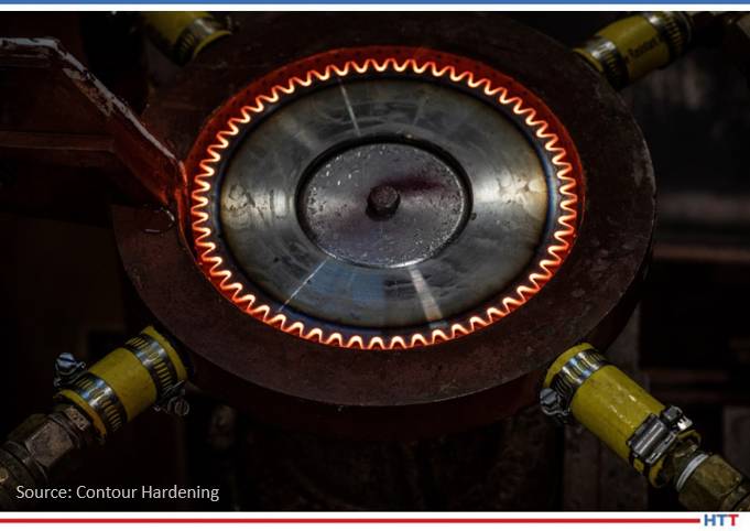
Induction Hardening Cast Iron

Induction hardening of cast irons has many similarities with hardening of steels; at the same time, there are specific features that should be addressed. Unlike steels, different types of cast irons may have similar chemical composition but substantially different response to induction hardening. In steels, the carbon content is fixed by chemistry and, upon austenitization, cannot exceed this fixed value. In contrast, in cast irons, there is a “reserve” of carbon in the primary (eutectic) graphite particles. The presence of those graphite particles and the ability of carbon to diffuse into the matrix at temperatures of austenite phase can potentially cause the process variability, because it may produce a localized deviation in an amount of carbon dissolved in the austenitic matrix. This could affect the obtained hardness level and pattern upon quenching. Thus, among other factors, the success in induction hardening of cast irons and its repeatability is greatly affected by a potential variation of matrix carbon content in terms of prior microstructure. If, for some reason, cast iron does not respond to induction hardening in an expected way, then one of the first steps in determining the root cause for such behavior is to make sure that the cast iron has not only the proper chemical composition but matrix as well.

(Dr. Valery Rudnev, FASM, Fellow IFHTSE, Professor Induction, Director Science & Technology, Inductoheat Inc.)


14 Quench Oil Selection Tips

Here are a few of the important factors to consider when selecting a quench oil. 

  1. Part Material – chemistry & hardenability 
  2. Part loading – fixturing, girds, baskets, part spacing, etc. 
  3. Part geometry and mass – thin parts, thick parts, large changes in section size 
  4. Distortion characteristics of the part (as a function of loading) 
  5. Stress state from prior (manufacturing) operations 
  6. Oil type – characteristics, cooling curve data 
  7. Oil speed – fast, medium, slow, or marquench  
  8. Oil temperature and maximum rate of rise 
  9. Agitation – agitators (fixed or variable speed) or pumps 
  10. Effective quench tank volume 
  11. Quench tank design factors, including number of agitators or pumps, location of agitators, size of agitators, propellor size (diameter, clearance in draft tube), internal tank baffling (draft tubes, directional flow vanes, etc.), flow direction, quench elevator design (flow restrictions), volume of oil, type of agitator (fixed v. 2 speed v. variable speed), maximum (design) temperature rise, and heat exchanger type, size, heat removal rate in BTU/hr & instantaneous BTU/minute.
  12. Height of oil over the load 
  13. Required flow velocity through the workload 
  14. Post heat treat operations (if any) 

(Dan Herring, “The Heat Treat Doctor®”, of The HERRING GROUP, Inc.)


How to Achieve a Good Braze

In vacuum brazing, be certain the faying surfaces are clean, close and parallel. This ensures the capillary action needed for a good braze.

A good brazing filler metal should:

  1. Be able to wet and make a strong bond on the base metal on which it’s to be applied.
  2. Have suitable melt and flow capabilities to permit the necessary capillary action.
  3. Have a well-blended stable chemistry, with minimal separation in the liquid state.
  4. Produce a good braze joint to meet the strength and corrosion requirements.
  5. Depending on the requirements, be able to produce or avoid base metal filler metal interactions.

(ECM USA)


Pay Attention to Material Chemistry

When trying to determine a materials response to heat treatment, it is important to understand its form (e.g., bar, plate, wire, forging, etc.), prior treatments (e.g. mill anneal, mill normalize), chemical composition, grain size, hardenability, and perhaps even the mechanical properties of the heat of steel from which production parts will be manufactured. The material certification sheet supplies this basic information, and it is important to know what these documents are and how to interpret them.

Certain alloying elements have a strong influence on both the response to heat treatment and the ability of the product to perform its intended function. For example, boron in a composition range of 0.0005% to 0.003% is a common addition to fastener steels. It is extremely effective as a hardening agent and impacts hardenability. It does not adversely affect the formability or machinability. Boron permits the use of lower carbon content steels with improved formability and machinability.

During the steelmaking process, failure to tie up the free nitrogen results in the formation of boron nitrides that will prevent the boron from being available for hardening. Titanium and/or aluminum are added for this purpose. It is important, therefore, that the mill carefully controls the titanium/nitrogen ratio. Both titanium and aluminum tend to reduce machinability of the steel, however, the formability typically improves. Boron content in excess of 0.003% has a detrimental effect on impact strength due to grain boundary precipitation.

Since the material certification sheets are based on the entire heat of steel, it is always useful to have an outside laboratory do a full material chemistry (including trace elements) on your incoming raw material. For example, certain trace elements (e.g. titanium, niobium, and aluminum) may retard carburization. In addition, mount and look at the microstructure of the incoming raw material as an indicator of potential heat treat problems.

(Dan Herring, The Heat Treat Doctor®)


Aqueous Quenchant Selection Tips

Determine your quench: Induction or Immersion? Different aqueous quenchants will provide either faster or slower cooling depending upon induction or immersion quenching applications. It is important to select the proper quenchant to meet required metallurgical properties for the application.

  1. Part material: Chemistry and hardenability are important for the critical cooling rate for the application.
  2. Part material: Minimum and maximum section thickness is required to select the proper aqueous quenchant and concentration.
  3. Select the correct aqueous quenchant for the application as there are different chemistries. Choosing the correct aqueous quenchant will provide the required metallurgical properties.
  4. Review selected aqueous quenchant for physical characteristics and cooling curve data at respective concentrations.
  5. Filtration is important for aqueous quenchants to keep the solution as clean as possible.
  6. Check concentration of aqueous quenchant via kinematic viscosity, refractometer, or Greenlight Unit. Concentration should be monitored on a regular basis to ensure the quenchant’s heat extraction capabilities.
  7. Check for contamination (hydraulic oil, etc.) which can have an adverse effect on the products cooling curves and possibly affect metallurgical properties.
  8. Check pH to ensure proper corrosion protection on parts and equipment.
  9. Check microbiologicals which can foul the aqueous quenchant causing unpleasant odors in the quench tank and working environment. If necessary utilize a biostable aqueous quenchant.
  10. Implement a proactive maintenance program from your supplier.

(Quaker Houghton)


Container Clarity Counts!

Assure that container label wording (specifically for identifying chemical contents) matches the corresponding safety data sheets (SDS). Obvious? I have seen situations where the label wording was legible and accurate and there was a matching safety data sheet for the contents, but there was still a problem. The SDS could not be readily located, as it was filed under a chemical synonym, or it was filed under a chemical name, whereas the container displayed a brand name. A few companies label each container with (for instance) a bold number that is set within a large, colored dot. The number refers to the exact corresponding SDS.

(Rick Kaletsky)


Check out these magazines to see where these tips were first featured:

The Chemistry Behind the Process: 6 Heat Treat Tips for Brazing, Induction, and Quenching Read More »

Industry-Academia Partnership Developing New Jominy End-Quench Test

OCHeat Treat Today was honored with the opportunity to visit the University of Akron and meet several senior engineering students in a Senior Capstone Program focused on a collaboration with heat treat industry leaders.

Applying their academic knowledge and background experience of heat treat and engineering, the students collaborated with and were mentored by Bill Stuehr of Induction Tooling, Inc. and Joe Powell of Akron Steel Treating Co. and Integrated Heat Treating Solutions. The result was an innovative new approach to push the bounds of heat treat. Read about how these students were a part of developing an induction and intensive quench heat treat solution.

By Bethany Leone, Editor, Heat Treat Daily 


“You'll never be bored of learning from others. And then, people learn to work as a team and come up with crazy ideas and make that dream a reality! That's [why] this is God's own country. Again, invention country.”
– Dr. Gopal Nadkarni Ph. D., University of Akron

Introduction

At the University of Akron, innovation and invention are being pushed to their limits. Senior engineering students under the guidance of Dr. Gopal Nadkarni have, for the second consecutive year, taken on heat treat theory and practice to test accepted norms in heat treat. But this isn’t just for an academic grade. Their collaboration with professional heat treaters in Ohio makes them engineers on the frontlines of advancing heat treat methodologies and part design.

Left to Right: (Top Row) Dennis Kopacz, Jared McLean, Shadoe Beatty, Tom Benenati, Matthew Yokosuk; (Bottom Row) Dr. Gopal Nadkarni, Bill Stuehr, Joe Powell

Dennis Kopacz, University of Akron ‘21: Age 23. “I’ve always been a problem-solver when I was in class and anything. I loved it . . . As a mechanical engineer, I feel we have a very, very broad spectrum of different avenues we can take.”

Jared McLean, University of Akron ‘21: Age 28. Prior to college, he worked four years in industry and would troubleshoot operations at his former manufacturing employer and was a big part of transitioning them to automation. Jared will return to his former employer and hopes to get his foot back into automation and learn more about design.

Shadoe Beatty, University of Akron ‘21: Age 23. Shadoe shared, “I do enjoy manufacturing. . . but I would like to be a design engineer as well.”[/tab][tab title ="Thomas (Tom) Benenati"]

Thomas Benenati, University of Akron ‘21: Age 22. “Understanding different material properties and how you can get those properties in different ways was really interesting. The induction and quenching project, just put a whole new perspective on that. . . As of right now, I just really like learning I really like. . . Every single engineering process, I’ve just been really interested in.”

Matthew Yokosuk, University of Akron ‘21: Age 23. “I’ve always been a hands-on learner, I’ve always loved to build things. . .So it just felt kind cool that I could go into something engineering where I could just build more.” Matthew is focused on looking for jobs in manufacturing.

Dr. Gopal Nadkarni Ph. D.: Academic professor who initiated the Capstone Senior Project between University of Akron students and Bill Stuehr and Joe Powell.

Bill Stuehr: Bill started his company in his parents’ garage. Now, Induction Tooling, Inc. is helping clients — and students — out of Ohio. Bill’s contributions in both a financial and mentorship capacity were thanked by students from both phases of the project.

Joe Powell: Joe Powell is a leading expert in quenching technology who leads Akron Steel Treating Company and Integrated Heat Treating Solutions in various, innovative heat treat applications. His knowledge on intensive water quenching, molten salt quenching, and gas quenching brought him into the fold, particularly in the second year of this project’s development of the patent pending modified Jominy + HPIQ™ end-quench tester that was developed with co-inventor, Bill Stuehr.

The Guinea Pigs

A senior project collaboration between the University of Akron and Induction Tooling, Inc. (ITI) began in the Fall of 2019. Can a heat treater conduct a Jominy end-quench test* by integrating induction heating above the quenching system versus using a furnace and having to carry the sample across the laboratory floor? This was the question that  this first group of students and their professor, Dr. Nadkarni, had for Bill Stuehr, president of ITI.

“I remember us telling Bill exactly what [we] wanted to do,” one senior engineer student recalled, “and his response was ‘So what is your budget?’ My answer was simply, ‘Well kind of [. . .] zero.’ I still look back and laugh, because I know that's not what he was expecting to hear. But that didn't stop Bill from wanting to help, and I know most companies would have laughed at us and walked us out.”

With Bill from ITI and Joe Powell from Integrated Heat Treating Solutions, the University of Akron students did design an induction to quench process with new machinery to perform a Jominy end-quench test in one space.

Bill Stuehr with Senior Project 2020: Induction Quench Tub.

“It's a green energy process,” described Stuehr, “so, we can put in an induction unit, heat the rod to a proper temperature using IR [infrared] to control that temperature to the feedback [going] to the induction unit, and then transfer it, drop it right into the Jominy quench, and do your testing. That way, it eliminates heating up a furnace and the energy it takes to [use it] and the dissipated energy that's wasted. And the transfer is almost immediate, because we're going to be heating in the same position [that] we're going to be quenching [the heated sample] with the Jominy tester.”

The students, having learned about traditional and innovative heat treat practices in this hands-on process, walked away with a deeper knowledge of heat treat and a deeper understanding of the  equipment that goes into the development of new processes. A graduating student from this first group in 2020 succinctly stated: “Working with Induction Tooling Inc. really made me want to understand more and more about induction heating. This technology, to me, used to be black magic, but now, getting to understand what is happening, it just keeps getting more and more fascinating.”

Taking the Induction Jominy End-Quench Test to the Next Level

Seeing the success of the first projects, the 2021 seniors and their professional heat treating partners decided to redesign the set-up based on the previous class’s work on integrating these two processes in order to intensively quench the part. Instead of a “drinking fountain,” the team set the goal on 400 PSI “instant-impact” quench on the end of the rod.

Going from a standard Jominy end-quench to an intensive quench with a blast of 400 PSI, said Jared, 2021 senior engineering student, was unthinkable. “At first,” Jared McLean, 2021 senior engineering student reflected, "I thought there's no way. But with the help of Bill and Joe in the design process, [we were] able to capture all that water . . ., and we got great results.” Further, Jared noted, the results mimicked the traditional Jominy end-quench test and “help prove intensive water quenching" can enhance the inherent hardenability for a given alloy.

The team went through a variety of designs, eventually deciding on the use of a different shaped sample rod, versus the traditional flat ended rod, for the test; the high pressure necessitated the use of a lid with one hole to contain the 400 PSI water coming from a “pepper shaker head” and redirect the excess water into the holding tank. In the words of the students, they used an inverted stainless steel “salad bowl” with a hole in the center that went on top of this structure to contain the high pressure quench media. An induction heated Jominy end-quench test rod (of a patent pending design) was lowered into the “salad bowl” hole to be quenched in situ.

Stuehr narrated how Jared, Dennis, and other students developed this construction:

“We [Jared, Dennis, and Bill] tested the [multi-hole] saltshaker [. . .] out in a parking lot on a cold day like today getting wet [. . .]. It didn't work.

“So, we decided, Okay, now what? Let's go down to one hole, so we have a [single-hole] pepper shaker. Now the pepper shaker [. . .] it's got a hole in it, right? And the water comes in through from the pump into the pepper shaker and shoots up and hits the end of this rounded rod. So, we tested it again in the parking lot, just shooting it out there, and [some of the] students did measurements in the tank to measure the flow to see if we could reach the four gallons per minute, at least 400 PSI, because we felt that's about what maximum we're going to be able to get out of this pump.

“We tested in the parking lot, and we're shooting it up to the roof. It looked pretty good. We were measuring the outflow, and we were matching the 4 gpm at about 400 PSI. So, then we took that, and then with the students help, we built a container.

“[We began testing.] First test worked perfectly. Worked perfectly, it just quenched out. You had to hold the handle down because we were afraid of ejecting the Jominy rod from the high pressure, but it contained the quench and did everything it was supposed to do[. . .] hitting the end of the rod and dissipating the quench around this end into this salad bowl, and then delivering the water back into the 55-gallon drum…”

The project was a success, and Dr. Nadkarni accepted the work between the students, Joe Powell, and Bill Stuehr. The students walked away with a better understanding of both traditional Jominy hardenability test standards and had actually developed a new heat treating tool to test the “maximum” hardenability of a given alloy of martensitic steel – all from this “crazy idea.”

2021 Student Reflections on Phase 2

Several of the senior students from the 2021 graduating class noted that their experience was a smooth transition from academics to hands-on heat treat equipment. Jared and another 2021 senior, Dennis Kopacz, said that they were constantly learning on the job; and with the knowledge of Joe Powell and Bill Stuehr, the work transition was smooth, since they had so much to do in such a short time.

Left to Right: Jared McLean, Bill Stuehr, Tom Benenati, Dennis Kopacz, and Shadoe Beatty.

Jared added that they learned a lot using the CNC computer numerical control router controls for the induction heater used to moderate the induction heating temperature and heating rate as well as the quenching process; everything was so precise, and it was incredible to see those types of processes.

“When I first got into the Senior Capstone Project,” Jared reflected, “I had very little knowledge of material science and getting into hands-on and really involved projects; I had to do a bunch of research on what was going on, and I learned a great deal, specifically about how heat treating works.”

These senior engineering students were also surprised at the success of the high pressure intensive water quenching method that Joe Powell and Bill Stuehr introduced to them. “We were in shock,” Dennis admitted, “because we didn't expect it to [work]." The expectation, Dennis continued, was that something would go wrong, like the lid would not be able to clamp down, or the container would leak. But when he and his classmate, Shadoe Beatty, 2021 senior engineering student, witnessed the successful increase in hardness, “it blew our expectation out of the water.”

Not only that, but the passion of this new method struck a chord with several students: “I think the most surprising thing for me was just even with the whole gravity of this project,” Matthew stated. “I think I speak for all of us: we didn't really know that much about material properties coming into this, but quickly, I realized that this project was . . . something almost groundbreaking, even.” He later added, “The opportunity to work with Bill especially has been eye opening to what is possible. Bill and his team at Induction Tooling were so eager to help, and our team is very appreciative of their willingness to support this project.  Their knowledge on this subject is invaluable for us graduating engineers.”

The Future

According to Dr. Gopal Nadkarni, each year, the process develops further: “Successive generation of student who [come] in get fired up, red hot; they learn the material properties. They learn the value in manufacturing.” He expressed his hope for changing heat treatment practice, saying that as each new round of students come through, they will raise the bar of heat treatment by working through this one project and developing new standards.”

Rising seniors, Josh Ramirez and James MacKita, are both looking forward to getting into the in-depth co-op as they finish their academics in 2021-2022.

Bill Stuehr said that as one sees the enthusiasm of the students on this project, “one can see underlying aspects of their personalities and how they contribute to the overall process of manufacturing in the United States in the future. This is their future, and this is what we're trying to encourage.”

*Editor’s note: Our friends over at Thermal Processing published an insightful article by D. Scott MacKenzie, PhD., FASM on this test. Find it here.

Industry-Academia Partnership Developing New Jominy End-Quench Test Read More »

Induction Heating + Radiation Heat Transfer

Source: heatprocessing

Today's shared content is provided by the global information partnership between leading European heat treat news provider heatprocessing and the team at Heat Treat Today.

What's next in heat treating carbon materials? In this best of the web feature from our European industry partner, heatprocessing, take a moment to see how computer modelling demonstrates the technical feasibility and the efficiency of this dynamic combination of induction heating and radiation heat transfer. Could this method be a practical integration in your heat treating process needs? Would adopting this method save you energy? Take a read and let us know!

An excerpt:

"This dynamic combination of induction heating and radiation during the baking process improves greatly the energy efficiency and permits a very precise control of the temperature profile in the carbon."

While we typically try to send our readers to free content, this article requires a nominal fee to access. We hope that you will find this content beneficial.

Read more at: "Modeling and experimental study of induction heating of carbon materials"

Induction Heating + Radiation Heat Transfer Read More »

Top 5 Benefits of Using Induction Heating for EV Manufacturing

Alternatives to internal combustion engines have long dominated conversations in the automotive world. Discover why induction heating is playing a vital role in the production of the electric vehicle in this Technical Tuesday original content article written by Michael Zaharof, regional sales and marketing manager at Inductoheat.

This article first appeared in Heat Treat Today's May 2021 Induction print edition. Find the digital upload and other past editions here.


Michael Zaharof
Regional Sales and Marketing Manager
Inductoheat

The electric vehicle (EV) sector of the automotive market is gaining momentum. Government mandates, fuel economy standards, and increasing consumer interest are all driving the push to EV. Some platforms are further along in the process, while others are just starting to enter the space. Many new ideas and vehicle configurations are being developed to deliver the best alternative to the internal combustion engine (ICE).

This industry is learning about the best way to configure drive mechanisms and control acceleration, be it a centralized power source operating a driveline or multiple motors powering different areas of the vehicle. Heat treating the necessary components properly to impart enough strength for the much higher torque delivery is more critical than ever compared to the traditional performance characteristics of those equipped on a standard ICE platform. Induction heating plays a critical role in the EV market as it permits several unique benefits over other thermal processing methods. Whether it is heat treating, shrink fitting, curing, or surface hardening, induction heating is one technology that has already proven itself to be beneficial for the manufacturing of electric vehicles.

Deeper Case Depth

Because of the almost instant torque delivery and fast acceleration characteristics of electric motors, EV driveline components must be more robust to handle the added torsional stresses. Combined with the need for wear resistance and fatigue life, these components must be heat treated to deliver these critical properties.

Induction heat treating of an automotive pinion

The powertrain components generally made with carbon steels (such as bearings, raceways, constant velocity joints, pinions, shafts, hubs, and gears), must be sufficiently hardened to provide enough strength, while remaining ductile enough to prevent premature failure. Induction hardening is ideal in many cases since it can deliver deeper hardened case depths, if desired, compared to other methods like conventional gas carburizing and nitriding. These alternative heat treatment methods must rely on diffusion mechanisms associated with a sustained and prolonged environment.

Alternatively, induction utilizes subsurface heating through electromagnetic current applied to a specified and customizable area achieving the desired casehardened depths. Because heat can be applied quickly to the specific area, electromagnetic induction produces much less metallurgical distortion compared to thermochemical methods that rely on through-heating and diffusion processes at high temperatures, which in some instances eliminates or diminishes the need for post heat treatment grinding or machining.

Fast & Flexible

The speed of manufacturing is an essential factor in keeping a supply chain moving and having enough product available. Many manufacturers and automotive part suppliers have adopted just in time (JIT) manufacturing workflow methodologies to increase speed to market while controlling production and inventory costs.

Induction heating of an automotive CV inner race

Induction hardening allows for parts to be processed as needed and in a way that does not require hours of processing time in contrast to alternative thermochemical heat treating methods. Because of the constant flow of individual parts and almost instantaneous time to heat, production can be incremental and consistent while still being flexible enough to adjust rates as needed. This flexibility and lean approach to inventory management can be more difficult when batches of parts are being processed together.

Also, because material distortion after induction heat treatment can be much lower, as previously mentioned, post-heat-treatment manufacturing operations can be reduced or eliminated.

Single Part Flow: Repeatability & Traceability

Part process flow is an important consideration when repeatability and traceability become essential, like in automotive manufacturing. When multiple parts are being processed simultaneously, such as in a furnace operation, individual parts cannot be validated while the heat treatment is in process. The part variability in batch operations can be impacted by part spacing, location in the furnace, gas concentration, and temperature from one batch to another.

Many quality standards require tight control of the heating process and data collection during heat treatment to ensure that acceptable parts are being made. Induction heating allows precise monitoring and real-time evaluation of each stage in the heat treat process. The parameters of the process cycle – such as quench temperature, quench concentration percentage, quench pressure, quench flow, energy used, frequency, and part rotation – are just some of the points that can be analyzed by today’s sophisticated sensors and signature monitoring systems.

Signature monitoring system by Inductoheat

Some of the more advanced monitoring systems, like those offered by Inductoheat, allow the user to “teach” the induction machine what a “good part” signature looks like as all the data points of the process are plotted throughout the cycle and compared to established acceptable limits. As the process runs in production, the user can validate that all critical factors being monitored are in specification.

In the event of an issue in which one or more points are out of specification, the part will be rejected by the quality system. The cycle processing data can be instantly associated with each heattreated piece through part marking/reading or the most suitable such as radio frequency identification (RFID),u for example, for storage and later use by the manufacturer.

Environmentally Friendly

Induction heating uses electricity as its means of heat generation. Other methods such as carburizing and different batch heating processes employ gases such as ammonia and other chemicals in conjunction with fossil fuel-powered furnaces. Induction heating is considered a clean and environmentally friendly option for heattreating.

The process uses electrical energy and can quickly cycle through the desired operation and then sit idle until needed again. Most alternative systems require warm-up and cooldown time before and after production runs. In some cases, it is less expensive to keep the furnace running while continuing to burn natural resources and vent exhaust gases into the environment compared to shutting the system down in between uses.

More Efficient 

Induction heating is a fast and efficient operation and can be scaled up easily to meet production requirements. Induction heating machines generally take up much less floor space than gas-powered batch furnaces. As mentioned above, they can be operated when needed without lengthy preheat or cooldown sequences.

Induction heating is associated with greater heat intensity, transferring more power directly to the workpiece in a concentrated fashion, compared to most other methods that rely on heating a surrounding environment. Induction coils can be designed to apply the required current density into an exact area of the part to be heat-treated instead of heating the entire piece.

The induction process is also more efficient as energy output can be controlled precisely to apply only the necessary power needed to obtain the desired temperature profiles at the desired production rate.

Induction heating of an automotive input shaft

Conclusion

Induction heating is a proven and environmentally friendly process that has a long history of precision and repeatability. The ability to heat parts quickly and more effectively is why many companies have opted for induction heating over other heat treat methods. Some other popular applications utilizing induction heating employed in EV production include shrink fitting, brazing, bonding, curing, battery production, stamping, forming, and varnishing of motor components.

Induction heating technologies are also dynamic, changing every day to meet new requirements and manufacturing goals. The use of multiple power levels and frequencies from a single induction inverter is one such innovation changing how some parts are being engineered and produced. Induction heating is a solution that will continue to assist the automotive manufacturing industry for years to come.

About the Author: Michael Zaharof is a regional sales and marketing manager at Inductoheat in Madison Heights, Michigan. He has been with the company since 2011 and has worked in the sales application, digital media marketing and outside sales departments. Michael has a bachelor of computer science in Information System Security. Michael currently works with customers in several states with their induction heat treating and induction forging needs.

Contact Mike at mzaharof@inductoheat.com.

Top 5 Benefits of Using Induction Heating for EV Manufacturing Read More »

Induction Hardening: Understanding the Basics

OCInduction is a curious member in the family of heat treating. Its presence is valuable, yet there’s a mystery surrounding it that has even veteran heat treaters exploring it to gain understanding. Journey through this induction hardening primer to learn about this important misfit of the heat treating world.

This Heat Treat Today Technical Tuesday original content feature, written by Kyle Hummel, P.E., COO at Contour Hardening, first appeared in Heat Treat Today's May 2021 Induction print edition. Feel free to contact Karen Gantzer at karen@heattreattoday.com if you have a question, comment, or any editorial contribution you’d like to submit.


Kyle Hummel, P.E..
Chief Operations Officer
Contour Hardening

In the world of heat treat, induction hardening just doesn’t fit in. There is no big furnace, cycle times are a matter seconds, and the entire process takes place right before your eyes rather than behind the walls of a furnace chamber. Many heat treaters have one old induction machine sitting in the corner of the shop floor, with one remaining employee who knows how to operate it.

Induction is different than all other types of heat treatment, and even many metallurgists shy away from the "black magic" that occurs during the process. When I ask customers how familiar they are with induction hardening, they usually state that they have seen it before, mention something about a coil, but that’s about the extent of their knowledge.

The purpose of this article is to give readers, who are not familiar with the induction hardening process, some background on the fundamental aspects and terminology of the process. The information encompasses the most common questions I am asked by new customers as well as information I would provide in training new employees. My hope is that it will give you enough familiarity with the process to become more comfortable engaging in a conversation about induction hardening.

Why Use Induction?

Selective hardening – Induction allows you to harden only the desired portion of a part, whereas most furnace-based heat treat processes treat the entire component. This means you can harden the particular area that you want to harden, while leaving the rest of the component soft enough to machine further.

Strength – Not only does the part become harder, but the stress (called residual compressive stress) that is induced into the part will make it stronger. Other processes can meet the improved wear resistance of the added hardness but fail to strengthen the part at all, or not as much as induction hardening.

Single piece flow – Because induction hardening is not a batch process (typically one part is hardened at a time), induction machines can be placed in a manufacturing cell, allowing the process flow to be uninterrupted.

Induction hardening in action

Equipment and Tooling

Induction Hardening Machine – Systems will vary significantly in size and complexity depending on the components they are hardening. The primary components of the machine consist of a power supply, heat station (transformer), workstation, and HMI. The fluids system is composed of quenchant to cool the part being hardened and distilled water to cool the internal components of the machine. Heat time, power supply output, part rotation, and quenchant parameters should be controlled, monitored, and logged for each part.

Power Supplies – Power supplies are the most important component of the induction hardener. For the purpose of this article, we will discuss the two most important outputs of the power supply, frequency and power.

Frequency is important because it will help determine the depth of heating. Lower frequencies heat deeper into the part, and higher frequencies heat closer to the surface. To remember this, I like to use the analogy of whales using very low frequency calls to communicate over miles and miles of ocean, whereas the high-pitched squeak of a mouse can only be heard several feet away. For induction hardening, frequencies are split into two groups: medium frequency (MF) and radio frequency (RF). The MF range is typically from 3-50kHz, and RF is from 100-400kHz.

Power is important because it will determine how large of a part you can harden, and how long the heat time will need to be. The more power that a machine can output, the larger the part it can harden and the faster it can harden to a specified case depth. Typical power supply outputs for induction hardening range from 25kW to 1MW.

Coils – The induction coil is a copper conductor that is shaped in order to harden the specified area of the part. The current that flows through the coil is what produces the magnetic field, which in turn heats the part. Coils are typically part specific, since they need to be precisely constructed to heat a particular portion of the part.

Modern induction coils are water cooled and can be made of tubing or machined copper pieces that are brazed together to make a particular shape to fit the part. They are frequently equipped with sections of a material called flux intensifier, which helps to drive the magnetic field in a certain direction in order to intensify heating in that area and make the coil more efficient.

It is also common to have the quenching designed into the coil (machine integral quench, or MIQ) so that quenchant can be applied immediately after heating without the need to move the part to an auxiliary quench mechanism.

Process Basics

Single Shot – Single shot hardening is the most common method of induction hardening where the part and coil remain in the same spot during the heating process. Typically, the part is brought into proximity of the coil, the heating and quenching processes are applied to the part, and then the part is removed from the coil.

Scanning – Scanning involves heating and quenching a small portion of the part while moving either the coil or the part until the desired area is hardened. Quench is directionally applied to the part so that as a new portion of the part is heated, the previously heated section is being quenched appropriately. Scanning is frequently used to harden shafts because heating the entire shaft at once would require too much power.

Dual Frequency – Dual frequency hardening combines the benefits of the deeper heating of the lower MFs with the surface heating capabilities of higher RFs. By utilizing two different frequencies, it is possible to contour the hardening pattern more effectively on gear-like components, which further improves the strength of the part. The frequencies can either be applied consecutively (low frequency preheat followed by a high frequency final heat) or simultaneously.

Induction Tempering – Induction can also be used to complete the temper process in a few seconds rather than furnace tempering which could take hours. Induction tempering takes place after the hardening process and involves heating the part to a much lower temperature than is required during hardening. The targeted temperature for induction temper is higher than that of furnace tempering due to the decreased temper time. This softens the hardened area slightly in order to increase the toughness of the part and improve crack susceptibility.

Quenching – The quench process is just as important as the heating process with induction hardening. Almost all modern systems use a water/polymer quenchant mixture in the range of 5-20% polymer instead of using oils. The quench media is typically sprayed on to the part rather than submerging it into a bath. Quench concentration, temperature, flow, and pressure must all be monitored closely for a robust process. These parameters all function to guarantee that the part is quenched properly and consistently to ensure the correct hardness is achieved and crack susceptibility is minimized. Quench media must also be filtered to remove any process waste that could potentially clog the quench spray holes.

Inspection – Like most other forms of heat treatment, the two most common specifications with induction hardening are case depth and hardness. Most specifications will require surface hardness measurements along with effective case depths to determine the depth of hardening.

Materials – The most common materials to be induction hardened are medium to high carbon and alloy steels, cast irons, and powder metal. Induction is also becoming a popular heat treat method on certain stainless steels in different industries.

Induction hardening in action

What to Look Out For

Cracking – The rapid expansion of the part during heating followed by shrinkage from the accelerated cooldown during quenching increases crack susceptibility of induction hardened parts. Not all parts have a high risk of cracking, but part characteristics such as internal holes, sharp edges, and certain higher carbon materials will require more consideration. If cracking is an issue, the first two areas to investigate are overheating and quench severity. Reducing the quench severity (increasing quench temperature and concentration, reducing flow and pressure) is typically the most effective means of reducing cracking within an induction hardened part.

Distortion – Another side effect of the rapid expansion and contraction is part distortion. It is impossible to not distort the part with induction hardening due to the phase changes in the metal. However, with a robust and carefully monitored process, it is possible to minimize and accurately predict process distortion. Faster heating times and technical expertise in fixturing methods are two common methods to reduce distortion.

Conclusion

Although this information just begins to scratch the surface of the terminology and fundamentals of the process, hopefully it provides a starting point to those with limited experience. Like many other forms of heat treatment, it can take years to develop the knowledge and skills to gain expertise in induction hardening. I have been involved in induction for almost fifteen years, and I find there is always a new application that gives me the opportunity to learn even more.

About the Author: Kyle Hummel is a licensed Professional Engineer who has worked for Contour Hardening for 15 years as a metallurgical engineer and currently manages operations of Contour’s Indianapolis location.

For more information, contact Kyle at khummel@contourhardening.com or 317.876.1530 ext. 333

Induction Hardening: Understanding the Basics Read More »

Message From the Editor: Survey: Heat Treaters Who Use Induction Heating Equipment

OCEver wonder what the status of induction heat treating is in North America? Well you can stop wondering: Check out these Induction Heating Survey results that represent approximately 450 induction units.

This original content article was written by Karen Gantzer, editor of Heat Treat Today, for Heat Treat Today's May 2021 Induction print edition. Feel free to contact Karen Gantzer at karen@heattreattoday.com if you have a question, comment, or any editorial contribution you’d like to submit.


Karen Gantzer
Managing Editor
Heat Treat Today

Heat Treat Today conducted a survey with those companies that perform in-house heat treating as well as commercial heat treaters who use induction heating equipment. The results represent approximately 450 induction units, and we received very interesting and beneficial information from the questions posed. Below is a sampling of the questions and responses.

When asked the number of induction coils owned, 27% have over 100 coils, 16% own 50 to 100, and 13.5% have ownership of between 16 to 30 coils. Interestingly, 50% of respondents design and make the vast majority of their induction coils.

There were eight different power supply and transformer selections noted in the results. 62.5% use IGBT generators, while 33.3% use vacuum tube generators, and tied for third with 25% of respondents using thyristor or MOSFET generators.

Surveys. Polls. While well-designed ones can require time to complete authentically, the effort is worth the data received because it helps many make informed decisions. Heat Treat Today believes that people make better decisions when they are well-informed, and so, with that thought in mind, if you’re interested in seeing the full report of this induction survey, please email me at Karen@heattreattoday.com.

Message From the Editor: Survey: Heat Treaters Who Use Induction Heating Equipment Read More »

How to Improve the Performance and Longevity of Induction Tooling Components

OCWhat is the most common cause of induction tooling failures? What is essential for the longevity of induction tooling? What is a vital component for induction tooling’s successful performance? This informative article shares the answers to these questions and provides valuable guidance for your induction needs.

This Technical Tuesday is provided by David Lynch, vice president of Engineering at Induction Tooling, Inc. and was featured in the Heat Treat Today’s 2021 May Induction print edition. Check out more original content articles in this digital edition or other editions here.


David Lynch
Vice President, Engineering
Induction Tooling, Inc.

Most induction heat treating applications are challenged with a harsh environment often dealing with high frequencies, high power, heat, smoke, steam, dirt, oil, quench fluid, quench additives, and contaminates. How induction tooling components are maintained in these harsh environments greatly impacts their performance and longevity.

The induction power supply, workstation, and material handling system should all be properly grounded. The work holding system should be level, square, and have proper alignment between the inductor coil and the workpiece for it to be heat treated. Part-holding fixtures should be held to a dimensional tolerance to ensure proper positioning and repeatability with minimal runout. The heat-treating process should include documentation of parameters including positioning (the air gap of the inductor coil relative to the workpiece), scan rates (in/sec), power (kw), frequency (kHz), heat time (sec), dwell time (sec), and quench time (sec). If auxiliary quench lines or nozzles are used, recording positioning data with pictures will guarantee repeatability of the process. Keeping track of quench water temperature, pressure, and flow along with percentage of polymer (aka viscosity) will help ensure consistent results. Keeping track of cooling water temperature, pressure, and flow is important in troubleshooting water cooling issues. The power supply should be routinely serviced and calibrated along with having an active preventative maintenance schedule.

Ball Race Inductors

Inductor coils should be properly designed to not only produce a heat treat specification, but also be of high quality, manufactured from quality materials with maximized water cooling and robust construction. Flux intensifiers should be properly matched to the operating frequency and attached to the inductor coil securely. Teflon insulators should be virgin grade and replaced if damaged or worn. Fasteners, fittings, and hose clamps should be non-ferrous such as brass or 300 series stainless steel. Hoses should be specified non-conductive and rated to meet or exceed supplied water pressure. Epoxies used should be rated for high temperatures and allow for expansion and contraction. Electrical contacts should be silver plated to provide superior contact and prevent oxidation.

Gear Tooth Scan Inductor

Manufacturing inductor coils is a skill that takes years to develop and several more to master. These tools can be made from copper tubing utilizing fabrication techniques with the use of bending fixtures and forming dies. Most tools today are machined from solid, raw materials often with complex geometries. To ensure quality and consistency, 5-axis CNC machining is often used. Thirty to forty percent silver braze should be used for joining the inductor coil components and sealing water-cooling passages. Designs should avoid sharp corners and provide smooth transitions for optimal current flow and minimal stress risers. Computer-solid models, engineering drawings, and process forms following ISO 9001:2015 certified standards guarantee a quality manufactured induction coil.

Ring Bearing Inductor

Inductor coils are precision handmade tools and should be treated as such. Inductor coils should be supplied in a heavy-duty case with packing materials to provide the proper support and protection during shipping and storage. Identification should be clearly marked on the case. Many cases are lockable as theft may be a concern. When inductor coils are removed from service, they should be cleaned with soap and water using a Scotch-BriteTM cleaning pad. Steel wool and steel bristle brushes should be avoided as the steel can imbed into the copper and may cause more harm than good. Once the inductor is cleaned, it should be closely evaluated for signs of wear or damage. If there are any signs of wear or damage, it should be sent out for maintenance or repair so it will be ready for the next use. After tools are cleaned and evaluated, cooling passages should be blown out with air and the inductor should be dry before sealed in the case and put into inventory. Notes and pertinent data related to the inductor can also be stored with it such as the number of parts processed, any modifications made to the inductor coil, and recorded setup data.

All of what was stated above about design and manufacture of inductor coils also applies to bus bars and quick-change adapters. These devices are used between the workstation and the inductor coil to bridge the gap closer to the workpiece. Originally developed for the automotive industry, quick-change adapters can drastically reduce changeover time, often without the use of hand tools. Since these devices are typically kept on the machine for long periods of time, it is important to check the condition and perform maintenance when needed. Scheduled maintenance of removal and cleaning of these devices will exceedingly increase their life. As with inductor coils, soap, water and a Scotch-BriteTM cleaning pad is all that is needed for these items; steel wool and steel bristle brushes should be avoided.

Multi-Turn O.D. Scan & Quench

When installing bus bars, adapters, and inductor coils with a bolted contact, it is extremely important to make sure that each of the mating surfaces are clean and free from debris. When dirt accumulates or ferrous debris is contained between the contacts, severe arcing and melting can occur.

It is also very important to use proper fasteners. For correctly fastening contact surfaces, 300 series stainless steel bolts with heavy brass washers are preferred. The heavy brass washers help distribute the load evenly and help prevent damaging the copper. The bolt threads should be inspected for wear and replaced new if there is any sign of wear or damage. It is also very important to verify that the length of the bolts will properly clamp without bottoming out before tightened. The recommended torque procedure for 3/8-16 stainless steel bolts is to tighten each bolt twice at 35 to 40-foot pounds. Special "break-away" bolts are available that are designed to fail beneath the washer if they are over tightened. This prevents damage to the threaded insert inside the copper contact. The remainder of the bolt can then be removed with pliers. This is much easier and less expensive than having to repair a bus bar contact or workstation transformer.

O.D. Scan with Quench

The workstation contacts, bus bars, adapters, and inductor coils are all electrical components that when energized are a live circuit, often with high power. The inductor coil produces a strong magnetic field used to heat the workpiece. There are also stray magnetic fields in the surrounding area. It is very important that everything in the surrounding area of these components be non-ferrous to prevent them from heating up. Something as simple as a steel hose clamp in close proximity to the magnetic field could heat up, causing a hose to melt, or a hose to come off, preventing water cooling and severely damaging the induction tooling or the induction machine. Steel fittings can rust and contaminate a water system very rapidly, choking the water flow internally and causing premature failure from low water flow. Any support structure to the induction tooling components should be a quality non-porous insulating material. Non-porous materials prevent liquid and contaminates from being absorbed and ultimately may cause a short circuit.

Proper water cooling is essential to the performance and longevity of tooling components. Both the induction power supply components and induction tooling components need to be properly cooled. Most power supply manufactures have a closed loop cooling system requiring deionized or distilled water. Most power supply manufacturers require that the cooling water temperature be maintained from 80 to 90 degrees Fahrenheit to prevent condensation inside the cabinet and on the circuitry. For cooling the inductor coil, bus bars, and adapters, deionized or distilled water is not necessary. Cooling water for these induction tooling components is best to be kept below 70 degrees Fahrenheit. This may require a separate cooling supply. Through laboratory experimentation and real-world production trials, it has been proven that lower cooling water temperatures can drastically increase the life of these components, especially in high volume, high power, short cycle applications.

The internal water-cooling passages of the inductor coil can play a significant factor in performance and longevity. Each inductor design should focus on maximizing water flow while minimizing sharp transitions.

The cooling water supply should come from a clean water source with a filtration unit of 25 microns placed just before it enters the induction tooling components. This guarantees that contaminates are filtered out, which may otherwise cause a low-flow or no-flow condition.

Quality non-ferrous fittings should be properly sized and configured to ensure the hoses are attached correctly to the induction tooling. It is very common to see 3/8" quick-change fittings used for cooling lines and 1/2" or 3/4" quick-change fittings used for quench lines. Using quick-change sockets for supply lines and quick-change plugs for return lines ensures the proper connections are made every time. Color-coding the hoses also helps in identifying water lines. It is very common to see blue hose for supply lines, red hose for return lines, and black hose for quench lines.

Single Shot Stem Inductor

Some inductor coils can be very small, having very limited water-cooling passages due to physical space. With these small inductors, it is even more important to have proper water cooling. In these situations, the use of a high-pressure booster pump may become necessary. These pumps can ensure cooling water continues to flow through these tight passages. Positive displacement pumps can also overcome steam pockets and help prevent vapor locks.

Problems with a cooling system can be detrimental to the performance and longevity of induction tooling components. Contamination in the cooling system can lead to low water flow. Problems with the water pump can also cause a low water flow condition. Then, low water flow can cause a steam vapor lock in the inductor coil leading to a rupture at a braze joint, a rupture through the tubing in a fabricated inductor coil, or a breach in the copper exposing the cooling chamber. Low water flow can also cause laminar flow internally which leads to thermal failure, resulting in exposed surface cracks through to the cooling chamber. Low water flow is sometimes identified by darkening of copper with purple color tones on the cooling return side of the inductor coil.

Wheel Bearing Single Shot Hardening

Induction tooling components cannot survive without water cooling. Symptoms include darkening of copper with purple color tones, melted copper, and catastrophic failure. Catastrophic failures caused by a no-water condition cannot be patched and require a major rebuild or replacement. It is a wise investment to have a flow indicator on the machine that prevents operation if there is no water flow or a low water flow condition.

All of what is stated earlier about the design and manufacture of inductor coils, bus bars, and adapters can also apply to quenches. These devices are used to evenly cool the part after heating to transform the structure consistently. Let’s discuss some of the important details in a quench system such as their design, fitting and hose requirements as well as pumps, filtration, and maintenance.

Quenches should be designed to provide a sufficient amount of quench to fully transform the metallurgical structure as specified. The quench pattern should be a uniform array of holes to quench the part at a proper impingement angle. The volume of water required should be matched with a supply having an inlet to outlet ratio not to exceed 1 in: 2 out. Hoses should be specified non-conductive and rated to meet or exceed supplied water pressure. Fittings should be high quality, non-ferrous without auto shutoffs, which can hinder quenching action and tend to clog more often.

Quenches can be a component that is kept on the machine for long periods of time. It is important to check the condition of these devices and perform routine maintenance. Scheduled maintenance of removal and cleaning these devices will exceedingly increase their life. Soap, water and a Scotch-BriteTM cleaning pad works well, and again, steel wool and steel bristle brushes should be avoided. Having a quench designed with bolted removable quench plates allows easy clean out.

Quench water needs to be filtered and contaminates kept at a minimum to improve performance and increase longevity of induction tooling components. A typical quench filter consists of a stainless-steel filter housing and a 100-microns bag filter. It is also very important to have a system for magnetic particle removal. Magnetic rod filters are available in many configurations, some that install inside the filter housing with the bag filter. Automatic separators are also often used. A low-cost alternative is to install a rubber coated magnet in the quench tank. In a non-ferrous tank, it can simply be dropped to the bottom. In a ferrous tank, it must be suspended to prevent the tank itself from becoming magnetized. All these methods can work, but only if they are properly maintained. A solid preventative maintenance schedule for these filters is essential.

Low Water Flow Failure

When filters are not used or maintained, tooling repairs are required more frequently. Common contaminates found inside quenches include oil dry, metal chips, and chewing tabaco. We see inductor coils come in for rebuild with a heavy patina of dirty, crusty contaminates. These contaminates are commonly a buildup of magnetic particles attracted by the magnetic field generated by the inductor coil. This patina accumulates and can create a short circuit, damaging the inductor coil.

To summarize, contamination is by far the most common cause of induction tooling failures. Water cooling is essential for longevity of induction tooling. Maintenance is essential for the performance of induction tooling. High quality, well-designed, robust induction tooling should be used for best results and consistency. Analyze induction tooling failures when they occur. Troubleshoot induction tooling rebuilds for possible machine issues. Look for methods of improvement with each opportunity. In closing, the best way to improve the performance and longevity of induction tooling components is to have open and frequent lines of communication with your tooling vendor.

About the Author: David Lynch is vice president of engineering at Induction Tooling, Inc. with 36 years of experience and is also the Deputy of the ISO quality system. He has created and developed the system and templates being used today for creating and tracking engineering drawings, job history, rate tracking, and job performance. David holds several design patents, has authored several published articles, and has often presented at technical sessions. He enjoys working closely with customers to develop valued solutions across a wide range of induction heating applications from initial design concepts to implementation, customer support and troubleshooting.

For more information, Contact David at dlynch@inductiontooling.com.

How to Improve the Performance and Longevity of Induction Tooling Components Read More »

Moving Beyond Combustion Safety

op-edIn this month’s column, John Clarke will expand his discussion beyond combustion safety to include the economic issues that are concerns to all equipment owners and operators.

This column appeared in Heat Treat Today’s 2021 Induction May print edition.

 John Clarke is the technical director at Helios Electric Corporation and is writing about combustion related topics throughout 2021 for Heat Treat Today.


John B. Clarke
Technical Director
Helios Electric Corporation
Source: Helios Electric Corporation

The furnace's or oven’s burner management system (BMS) and its associated components are all that stand between us and an incident. The severity of these incidents ranges from the very expensive — a damaged furnace or oven — to the tragic — loss of a human life. It is a testament to the good work of hundreds of people that combustion system explosions are so rare. That said, the risk to life and property mandates that we revisit this subject frequently, and the risk to profitability dictates we expand our consideration beyond safety to include uptime and quality, as well.

National Fire Protection Association Standard 86 (NFPA 86), or “Standard for Ovens and Furnaces,” provides a standard that is the most common guide to the application of combustion components used in the US. This excellent prescriptive standard reflects the common thinking of people with hundreds of years of combined experience; but it still requires expertise to properly interpret and apply its requirements. It is important to not only understand what component must be provided, but also why.

NFPA 86 is used as a guide for the design of your BMS which includes the various control components to properly monitor the startup and operation of the burner. NFPA 86 also applies to the fuel train, constructed of components that regulate the flow of fuel and air and includes blowers, regulators, valves, filters, and sensors. What BMS and fuel train safety system issues should most concern an end user? An end user must know what it really means when your system is stamped “NFPA 86 Compliant.” To paraphrase Clint Eastwood: The end user needs to know their system’s limitations.

The NFPA 86 standard has been developed to protect life and property, but not production and profits. It is also a prescriptive standard, providing specific guidance to what components need to be applied and in what order. The shortcoming of a prescriptive code is that it must be mostly generic, that is, it applies to types or classes of equipment as opposed to specific applications. Given the variety of burner applications used in industry, it would be impractical to specify every component, order, and wiring for every conceivable process heating application.

Why is this a concern for end users? A specific application may have unforeseen risks or are out of the scope of NFPA 86 . Critical failure modes may be indirectly associated with a burner failure. For example, loss of a process air flow may allow a heat exchanger to overheat before a high temperature limit instrument detects the temperature rise. In this case, the process air flow must be monitored, and the flow or pressure switch monitoring the air flow must be added to the interlock string. This way, the burner will shut off as soon as the air flow failure is detected and not wait for the heat exchanger’s temperature to rise to an unsafe temperature. Another reason to “exceed” the code is that often ovens or furnaces are one element in a much larger manufacturing system. An example would be a continuous paint line, where a failure of the curing oven might shut down an entire facility.

What should an end user do? Ensure the system provided meets the standards and codes, NFPA 86, the Fuel Gas Code (NFPA 54), NEC, etc. This level of compliance is the minimum – and is often not the optimal. Additionally, invite the OEM who built the system to apply their experience and exceed the standards if it provides a more robust system. It may cost a few dollars up front, but it will be pennies when compared to the cost of an incident or, in many cases, an outage.

Encourage your supplier to apply a recognized process to the system review, perhaps a failure mode effects analysis (FMEA) and factor in not only the cost of an incident, but the cost of lost production or quality rejects as well. Consider an independent third-party review – it never hurts to get a second opinion. Review the cost of redundancy, be it online or near online . What is the cost of a second flame rod and flame safeguard when compared to the value of four hours of production?

Next, review the steps to service the system. Look at the mean time to replace (MTTR) a failed component. Has the system been designed to be easily serviced? Are there pipe unions on either side of all critical valves? Where are the spare parts located? What skill trades are required to make the repair? Is post replacement calibration or testing required? And if so, has it been documented?

Ask if the BMS provides a clear indication of the reason for a shutdown. The interlock string, a logical series wiring of critical components where any one component indicating a fault will disable the combustion system, should be monitored in a way where the “first out” or component that will shut down the system, is clearly identified.

Lastly, it is the end user’s responsibility for periodic inspections and equipment maintenance. NFPA 86 prescribes that the BMS and fuel train components are inspected per the manufacturer’s recommendation, but at least once a year.

The annual inspection is a critical step for safe operation but is viewed by many end users as simply a cost. Add to this the relative reliability of most components and we are presented with the ironic risk that maintenance personnel may take short cuts during the periodic inspection. One such person may say, “I always check the low gas pressure switches and they always pass, so I thought, what would it hurt if I skipped the test this year?”

For a more robust inspection, consider adding more value to the process. Combine the safety inspection with an extensive equipment calibration and service: Replace the filters, change the thermocouples, calibrate the control instruments, tune the burner, check the fuel-to-air ratio of the burner, and inspect the BMS components. This adds value to the process and makes it more palatable for the maintenance department.

When the cost of downtime of a key piece of equipment is high, practice the repair, at least on paper. However, if a failed burner shuts down an automotive assembly line, isn’t it worth the time to run actual drills?

In general, most burner trips are the result of a failed sensor, a UV scanner, dirty flame rod, an open thermocouple, or the vibration from an unbalanced fan tripping a pressure switch. In other words, when this type of trip occurs, the greatest cost is lost production, followed by the labor to diagnose the problem and then the cost to replace the component. Generally, the purchase price of the component is far less than the other costs associated with the system trip. Do not be penny wise and pound foolish. Spare parts are a pretty good investment.

If you need the heat from a burner to make your product, it makes sense to not only consider safety, but also plan reduced downtime as well. In the coming articles, we will examine these issues in greater detail, so stay tuned.


References:
[1] https://www.nfpa.org/codes-and-standards/all-codes-and-standards/list-of-codes-and-standards/detail?code=86


About the Author:

John Clarke, with over 30 years in the heat processing area, is currently the technical director of Helios Corporation. John’s work includes system efficiency analysis, burner design as well as burner management systems. John was a former president of the Industrial Heating Equipment Association and vice president at Maxon Corporation.

Moving Beyond Combustion Safety Read More »

Red Hot Basics: The World of Induction

Source: Inductoheat.com

In preparation for Heat Treat Today's May Induction magazine, here is a best of the web to end your week on.

How do they do it? What happens to metals when they are being induction heated? If you've had experience with heat treating using induction, how does it compare to other forms of heat treatment? This helpful article runs down the basics of induction and includes a video with different phases of the process. Check it out!

"As current flows through a medium, there will be some resistance to the movement of the electrons. This resistance shows up as heat (The Joule Heating Effect). Materials that are more resistant to the flow of electrons will give off more heat as current flows through them, but it is certainly possible to heat highly conductive materials (for example, copper) using an induced current."

Read more: "What is Induction Heating?"

Red Hot Basics: The World of Induction Read More »

8 Heat Treaters Improve Processes with Simulation Software

Source: CENOS

Heat Treat Today brings you this best of the web content to highlight how 8 companies have been using simulation in their heat treat processes. In the article, the companies attest to saved time and costs as well as the benefits of visualizing accurate results. Check it out!

An excerpt:

[blockquote author=”CENOS” style=”1″]Old coil design failed and started leaking after 20,000 shots, while the redesigned coil is still running after 122,000 shots – more than five-fold improvement of the coil lifetime. By summing all of the benefits of the simulation software adoption in the engineering routine of the plant, Kevin got a 9% increase of the overall equipment efficiency (OEE).[/blockquote]

Read More: “8 Stories on How Computer Simulation Helped Companies to Improve Induction Heating in 2020”


All images provided by CENOS.

8 Heat Treaters Improve Processes with Simulation Software Read More »