Ernesto Perez, Director of Engineering, Nutec Bickley
In today’s Heat Treat TodayTechnical Tuesday feature, Ernesto Pérez, Director of Engineering, at Nutec Bickley, introduces readers to different options when it comes to furnace temperature control.
The main aim of the temperature control function is to keep a furnace operating within certain predefined values and it is composed of two main parts:
Electronic control element, usually a PID (proportional–integral–derivative) controller
Mechanical components
In this article we will look at the various control modes used in industrial furnaces, and their applications for various heat treatment processes.
Back to the Beginning: “Zero Control” Mode
Figure 1
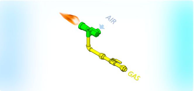
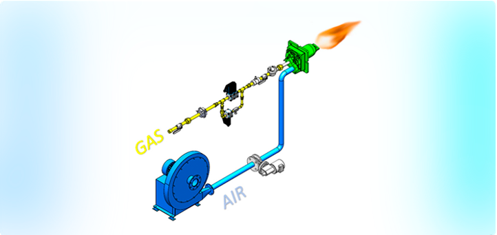
Before considering the modes currently used, we should briefly mention the “zero control” mode found in earlier furnace models, employed some time back, also known as “atmospheric mode.”
This mode operates by taking air from the environment by means of the venturi effect to perform combustion without controlling the air flow, resulting in an inefficient use of energy. (Figure 1)
Fuel-Only Control System
Figure 2
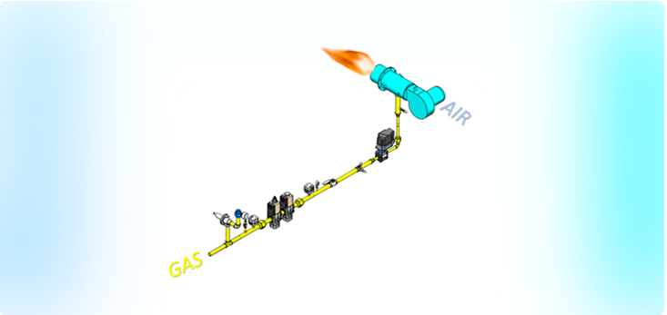
This operates in a similar way to zero mode, where only the gas is controlled. However, instead of the air being introduced by the venturi effect, there is a turbo fan that provides a constant flow to the process, while the gas is regulated during the different stages of combustion. (Figure 2)
Economic system having a single line of control.
It provides good temperature uniformity in applications where all items being fired in the furnace need to be at the same temperature.
Ideal for low temperature furnaces, kilns for ceramics and applications that require high-level heating homogeneity.
Possible Disadvantages This technique leads to high gas consumption due to the heating of all the air present, irrespective of the size of the load in the furnace.
Proportional Control System
Figure 3
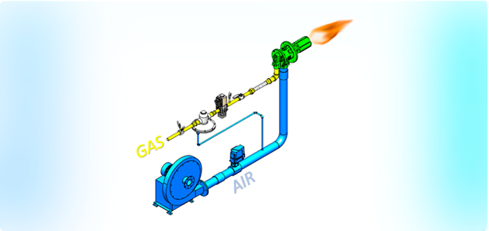
With this control mode, the air and the gas are controlled proportionally. (Figure 3)
The operation starts with a small flame, and as the temperature rises, it grows as the air and gas levels increase.
This system allows you to adjust the amount of gas based on the air present in order to achieve perfect combustion and optimal fuel consumption.
Ideal for any type of furnace, for example for heat treatments such as aging, tempering, forging and normalizing.
Possible Disadvantages At the beginning of the heating process, it can be the case that temperature uniformity across the entire furnace is not so good due to the small flame, so it is not a system recommended for the treatment of very fragile pieces that can break.
Mass Flow Control System
Figure 4
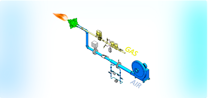
This system controls air/gas in the same as the previously described method, but it also gives allowance to vary the air/gas ratio during combustion process in order to optimize the fuel. (Figure 4)
It enables for the achievement of optimal combustion conditions with less energy input.
If more air is needed in a particular heat treatment stage (usually at the beginning), it can be temporarily increased.
Ideal for any type of furnace, like heat treatments such as aging, tempering, forging, normalizing and applications involving fragile products.
Possible Disadvantages Because of the technology behind the system, it is more expensive.
Pulse Control System
Figure 5
This is one of the most recently introduced methods that provides a fixed air/gas ratio, but unlike the previous mentioned systems, flame velocity for product heating is always high, which generates ideal temperature uniformity right from the beginning of the cycle. (Figure 5)
The burners pulse from high-fire to low-fire, repeating this cycle every 15 to 60 seconds.
It is cheaper to operate than the mass flow system, allowing users to handle the entire range of products with a smaller investment.
It provides greater fuel efficiency by heating the product evenly from the beginning.
Ideal for any furnace, for example for heat treatments such as aging, tempering, forging, normalizing and applications involving fragile ceramic products.
Possible Disadvantages The radiation of the flame can affect certain products; however, by installing an additional instrument it is possible to control this effect and to reduce flame radiation.
Experts in Temperature Control
Nutec Bickley can offer all current systems, advise on the most appropriate choice with the best cost benefits, update old systems with current technology, and provide repair and spare parts services for existing temperature control systems.
About the author: Ernesto has been sharing his expertise at Nutec for 18 years. As an electronic system engineer with a master’s degree in artificial intelligence, the 25-year industry veteran has been focused on the control aspect of software and hardware.
Climate change and fossil fuels are topics that can spur many lively conversations. In today’s Heat Treat TodayTechnical Tuesday feature, explore their connection as it relates to heating industrial furnaces in the future with Dr. Joachim G. Wüenning, president, WS Inc. and an expert in clean efficient combustion.
Many people view climate change as the biggest threat to mankind. Technical and social efforts will be required to meet the goals, formulated in the “Paris Climate Agreement,” to limit global warming to less than 35.6° F (2° C).
Combustion of fossil fuels is by far the largest human contribution to global warming. Fossil fuel-fired power plants and internal combustion engines are already in the public focus. The transformation to alternative drives for vehicles has just started, and the days of coal-fired power plants are numbered.
Combustion of fossil fuels for industrial furnaces is also a large contributor to greenhouse gases and air pollution. The industrial heating sector is not in the public focus yet, but that will change soon; therefore the topic should be addressed proactively.
For mid- to long-term future industrial process heating, there are three main scenarios:
heating with renewable electricity, or
heating with non-fossil fuels, or
a combination of both.
Humans used non-fossil fuels for hundreds of thousands of years and are returning to that habit after a short period of about 250 years where fossil fuels were primarily used.
Reducing CO2 Now and In the Future
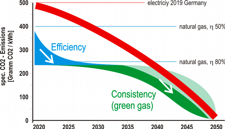
Heating a furnace using electricity is locally CO2 free, but an even greater amount of CO2 is emitted at power plants since the majority of electricity is generated by burning fossil fuels. For every kilowatt hour (kWh) produced, roughly one pound (~0.45kg) of CO2 is emitted into the atmosphere [1]. This is true for Germany, and the figures for the United States are in the same range.
Heating an industrial furnace with a typical temperature of around 1832°F (1000°C) with natural gas produces about 0.4kg CO2 for every kWh of available heat for a cold air burner, and less than 0.25kg/kWh CO2 when using a recuperative or regenerative burner where waste heat is recovered using a heat exchanger.
So, the short-term measure to reduce CO2 emissions is to use an efficient burner with heat recovery or to switch from electric to natural gas heating, which can cut CO2 emissions by 50% or more.
For a further reduction, we have to wait until electricity generation becomes predominantly regenerative, or we have to use green, non-fossil fuels. The possible paths to non-fossil heating of industrial furnaces are drafted in Figure 1. It shows that the short-term action should be improving the efficiency of burner systems or a switch from electric to gas heating. In the mid- to long-term future, there should be a healthy competition between non-fossil fuel gas and electricity, driving the prices for non-fossil energy down.
Figure 1
Changing Fuel Compositions
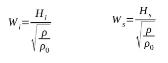
The most relevant characteristic for the interchangeability of fuel gases is the Wobbe Index (Figure 2), with the lower or upper heating value (Hi, Hs), the density of the fuel gas (r) and the density of dry air (r0). Fuel gases with the same temperature, pressure, and the same Wobbe Index will provide the same energy output from a burner. If the Wobbe Index is changing, the flow must be corrected by changing the fuel gas pressure or a flow throttle device to keep the burner power constant.
Figure 2
In most cases, the air does not need to be corrected since the ratio between stoichiometric air ratio and lower heating value is about 0.95 m3/kWh for common hydrocarbons. That means that a burner with a given heating power needs the same amount of air even when different fuel gases are used. A good rule of thumb is that one cubic meter per hour of air is required for every kilowatt of heating power.
If hydrogen is used as a fuel, about 15% less air is required. So, when hydrogen is added to natural gas and the fuel gas flow is corrected but the air flow is left unchanged, the system would be operated with somewhat more excess air, slightly less efficient but safe.
If gas fluctuations will occur in the future, adjusting the burners with more excess air would be an easy measure to ensure safe operation. With an effective heat recovery system and low exhaust gas temperatures, efficiency losses would be minimal.
Fuel Gases With High Hydrogen Content or Pure Hydrogen
The flame speed of hydrogen is much faster compared to hydrocarbons. That can cause some problems, especially in premixed burners where a flashback can occur. Another challenge resulting from faster combustion could be higher flame peak temperature leading to higher thermal NOx emissions. Modern low NOx methods are available to address this problem.
A positive effect of hydrogen can be a more reliable and easier ignition of burner systems. Many industrial burner systems can be operated with high percentages of hydrogen or with pure hydrogen with little or reasonable modifications.
Fuel Gases Containing Fuel Bound Nitrogen
Using ammonia or bio-gases with fuel bound nitrogen will produce excessive amounts of NOx-emissions when burned in most burner systems. There are a number of options to achieve low NOx-combustion with fuel bound nitrogen.
One method is fuel conditioning where fuel bound nitrogen is broken up into molecular nitrogen. This was successfully demonstrated using a stainless steel reactor in combination with a flameless oxidation burner system.[2] Another method would be exhaust gas cleaning by selective (SCR) or non-selective (SNCR) catalytic exhaust gas cleaning. Both processes require large investments and operating costs and should only be used if other options are not available.
The development of combustion systems with integrated treatment of fuel bound nitrogen would be the preferred method and will be an important topic for combustion research in the coming years. One approach is multi-stage flameless oxidation [3].
Fuel Conditioning
Fuel conditioning might be required to keep fuel gas properties within regulated limits inside the gas transport and distribution grid or for certain customers with special requirements. Fuel conditioning can be performed by blending different gases or by changing their compositions by using reformers or gas separation units like pressure swing adsorption (PSA) or membrane technology.
If future regulations propose a certain hydrogen content in the fuel gas grid, strategically placed steam reformers could keep the hydrogen content within certain ranges, even if there is no regenerative electricity available to operate electrolysers.
Reformers could also crack ammonia, ethanol, or methanol before being used as fuel gas to heat processes.
Outlook
There are several options towards non-electric, fossil-free industrial process heating. All these options have to be thoroughly investigated to keep a number of options open for future energy systems. The energy system of the future will be based on regenerative power generation but it will involve additional energy carriers to store and transport the energy. There are some challenges for combustion but there is no doubt that these can be overcome.
A fair and open competition between the different energy options will create the best solutions for society and the planet. A planned economy will not provide the fertile soil for innovations and entrepreneurship necessary to meet the challenges.
References
[1] German Environment Agency, CO2 Grid Emission Factors from 1990 – 2018 for the German Energy Mix, March 2019
[2] Domschke T., Becker C., Wüenning J.G., Thermal Use of Off‐Gases with High Ammonia Content – a Combination of Catalytic Cracking and Combustion, Chem. Eng. Technol., 21: 726-730
About the Author: Joachim G. Wüenning is president of WS Wärmeprozesstechnik GmbH and his area of expertise is in clean efficient combustion, FLOX—flameless oxidation, heat recovery, radiant tubes, and recuperative, regenerative burners. This article originally appeared in Heat Treat Today’sMarch 2020 Aerospace print edition.
This article on the critical role of valve safety trains in the prevention of catastrophic fuel-delivery accidents at heat treating facilities is authored by Robert Sanderson, P.E., Director of Business Development in the Combustion Safety division of Rockford Systems, LLC, based in Rockford, Illinois. Valve safety trains require regular inspections, maintenance, and training.
Heat treating, a thermal process used to alter the physical, and sometimes chemical, properties of a material or coating, is a high-temperature operation that involves the use of heating or chilling, normally to extreme temperatures, to modify a material’s physical properties — making it harder or softer, for example. Applications for heat treating are virtually endless, but at the heart of all thermal processes is the valve safety train.
These fuel-delivery devices maintain consistent conditions of gasses into furnaces, ovens, dryers, and boilers, among others, making them crucial in assuring safe ignition, operation, and shutdown. Equally important, they keep gas out of the system whenever equipment is cycled or shut off.
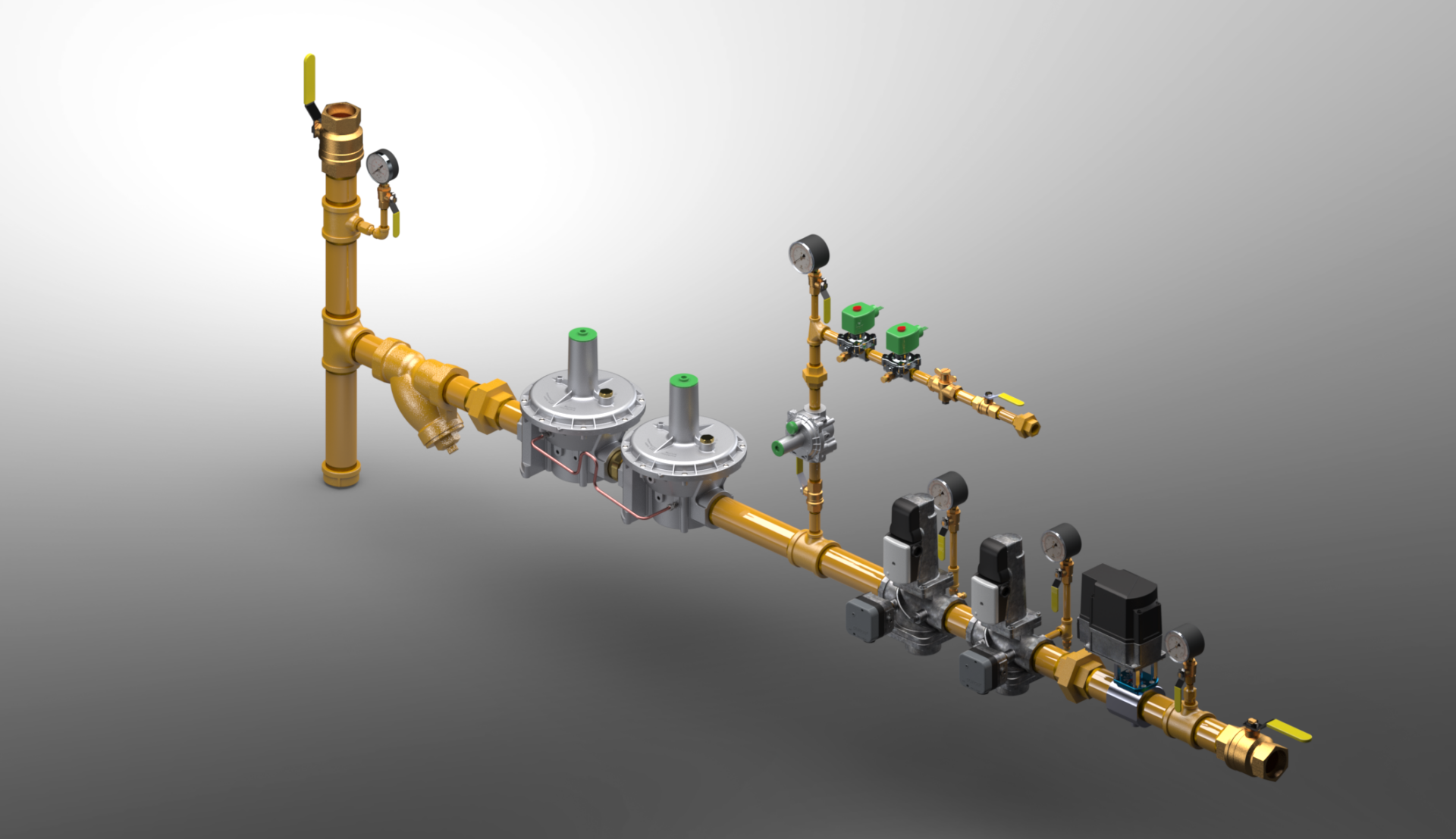
A valve safety train isn’t a single piece of equipment. Instead, it has many components including regulators, in-line strainers (“sediment traps”), safety shut-off valves (SSOV), manual valves (MV), pressure switches, and test fittings logically linked to a burner management system.
Flame-sensing components make sure that flames are present when they are supposed to be, and not at the wrong time. Other components may consist of leak-test systems, gauges, and pilot gas controls. At a minimum, there are two crucial gas pressure switches in a valve safety train, one for low pressure and one for high pressure. The low gas pressure switch ensures the minimum gas pressure necessary to operate is present. As you would assume, it will shut off fuel to the burner if the gas pressure is below the setpoint. The high gas pressure switch ensures excessive pressure is not present. It too will shut off fuel if the gas pressure is too high. Both switches must be proven safe to permit operation. Additionally, there will be an air pressure switch to ensure sufficient airflow is present to support burner operation.
Some systems have supplementary pressure switches, such as a valve-proving pressure switch. Switches such as these are typically used to enhance safety or provide other safety aspects specific to that application’s needs. A multitude of sensors within the valve safety train — pressure switches, flame detectors, position indicators — and isolation and relief valves work together in concert to prevent accidents.
Valve safety trains must be compliant with all applicable local and national codes, standards, and insurance requirements. The most common of these for North America are NFPA, NEMA, CSA, UL, FM. Annual testing and preventive maintenance are not only an NPFA requirement, but also oftentimes required by insurance agencies, equipment manufacturers, and national standards, including ANSI, ASME, and NEC.
Set Your Trap
The primary function of a valve safety train is to reliably isolate the inlet fuel from the appliance. Safety shut-off valves are purposely selected to do this. To protect these valves, the initial section of a safety train is used to condition the fuel and remove debris that could potentially damage or hinder all downstream safety components.
The first conditioning step is a sediment trap (a.k.a. dirt leg, drip leg). This trap captures large debris and pipe scale and provides a collection well for pipe condensates. The proper orientation of a sediment trap is at the bottom of a vertical feed. This downwards flow arrangement promotes the capture of debris and condensate into the trap. A horizontal feed across a sediment trap is an improper application. The second conditioning step is a flow strainer or filter element. These devices are fine particulate sieves. The removal of fine particulates from the fuel stream further protect the downstream safety devices from particulate erosion and abrasion. Taken together these conditioning steps remove particulates and condensates that might block, hinder, erode, or otherwise compromise the safety features of the downstream devices.
The Explosive Force of a Bomb
Owing to the presence of hazardous vapors and gases, a poorly designed or inadequately maintained safety train can lead to catastrophic accidents, ranging from explosions and fires to employee injuries and death. When this explosive force is unleashed, the shock wave carries equipment, debris, materials, pipes, and burning temperatures in all directions with tremendous force.
The following incidences provide just a few examples of why it is important to purchase the highest quality valve safety train and to keep it professionally maintained, inspected, and tested.
In 2018, a furnace explosion at a Massachusetts vacuum systems plant killed two men and injured firefighters as a result of fuel malfunction.
In Japan, an automobile manufacturer lost tens of millions of dollars when it was forced to shut down production for nearly a month after a gas-fueled furnace exploded due to flammable fumes building up in the tank.
In a Wisconsin bakery, an employee was seriously injured when he ignited an oven’s gas and was struck by a door that was blown off. A malfunctioning valve had allowed natural gas to build up inside the oven.
In 2017, a van-sized boiler exploded at a St. Louis box company, killing three people and injuring four others. The powerful, gas-fueled explosion launched the equipment more than 500 feet into the air.
In 2016, a boiler explosion in a packaging factory in Bangladesh enveloped the five-story building in flames, killing 23 people.
Two Dangers: Valves and Vents
Valves are mechanical devices that rely upon seats and seals to create mechanical barriers to control flow. Over time, these barriers wear out for a variety of
Glassblowing Furnace with Pipes
reasons, whether it is age, abrasion, erosion, chemical attack, fatigue or temperature. Increased wear contributes to leaks, and leaks lead to failures and hazards. Defective valves can allow gas to leak into a furnace even when the furnace is not in operation. Then, when the furnace is later turned on, a destructive explosion could occur.
Testing a valve’s integrity is an evaluation of current barrier conditions and may be used to identify a valve that is wearing out prior to failure. As such, annual valve leakage tests are an important aspect of a safety valve train inspection program. Along with annual testing, valves should be examined during the initial startup of the burner system, or whenever the valve maintenance is performed. Only trained, experienced combustion technicians should conduct these tests.
Improper venting is another danger. Here is the problem: Numerous components in a valve safety train require an atmospheric reference for accurate operation. Many of these devices, however, can fail in modes that permit fuel to escape from these same atmospheric points. Unless these components are listed as “ventless,” vent lines are necessary. Vent lines must be correctly engineered, installed, and routed to appropriate and approved locations. In addition, building penetrations must be sealed, pipes must be supported, and the vent terminations must be protected from the elements and insects. In short, vent lines are another point of potential failure for the system.
Even when vent lines are properly installed, building pressures can vary sufficiently enough that they prevent optimal burner performance. Building pressures often vary with seasonal, daily weather, and manufacturing needs, further complicating matters. Condensate in vent lines can collect and drain to low points or into the devices themselves. Heating, cooling, and building exhausters are known to influence building pressures and device responses, but so can opening and closing of delivery doors for shipping and receiving. Hence a burner once tuned for optimal operation might not be appropriately tuned for the opposite season’s operation.
The smart alternative to traditional vented valve trains is a ventless system that will improve factory safety and enhance burner operation. Ventless systems reference and experience the same room conditions where the burners are located, resulting in more stable year-round operating conditions, regardless of what is happening outside. Additionally, ventless designs typically save on total installation costs, remove leaky building penetrations, eliminate terminations that could be blocked by insects, snow or ice, improve inspection access, and ensure a fail-safe emergency response.
Final Thoughts
Valve safety trains are critical to the operation of combustion systems. Despite being used daily in thousands of industrial facilities, awareness of their purpose and function may be dangerously absent because on-site training is minimal or informal. To many employees on the plant floor, this series of valves, piping, wires, and switches is simply too complex to take the time to understand. What is known can be dangerously misunderstood.
Understanding of fuel-fired equipment, especially the valve safety train, is necessary to prevent explosions, injuries, and property damage. The truth is, although valve safety trains are required to be check regularly, they are rarely inspected, especially when maintenance budgets are cut. And while codes require training, they offer very little in terms of specific directions.
As a safety professional, the onus is on you. You and your staff must have a core level of knowledge regarding safe practices of valve safety trains, even if a contractor will be doing the preventive maintenance work. Most accidents and explosions are due to human error and a lack of training when an unknowing employee, for example, attempts to bypass a safety control. Preventive maintenance is essential to counter equipment deterioration, as is the documentation of annual inspection, recording switch set points, maintaining panel drawings, and verifying purge times. Accidents happen when this type of documentation is not available. Don’t wait for a near-miss or accident to upgrade your valve safety train.
During the day-to-day operation of heat treat departments, many habits are formed and procedures followed that sometimes are done simply because that’s the way they’ve always been done. One of the great benefits of having a community of heat treaters is to challenge those habits and look at new ways of doing things. Heat TreatToday‘s 101 Heat TreatTips, tips and tricks that come from some of the industry’s foremost experts, were initially published in the FNA 2018 Special Print Edition, as a way to make the benefits of that community available to as many people as possible. This special edition is available in a digital format here.
Today, we offer one of the tips published under the Combustion category.
Combustion
Heat TreatTip 50
Effect of Exhaust Gas Temperature vs. O2 on Efficiency
Tuning a burner properly is important for safety. Tuning can also have a significant effect on efficiency in some but not all cases.
The efficiency of a conventional cold air burner varies significantly with the amount of excess air (related to % O2 in the exhaust products). Since a cold air burner does not use the exhaust gas to preheat the combustion temperature, the exhaust gas temperature is essentially equal to the furnace temperature. For a cold air burner operating at a 1,850°F, reducing excess air from 20% to 10% (reducing O2 from 4% to 2%) will increase efficiency by almost 5%.
Modern high-efficiency burners use the exhaust gas to preheat the combustion air as it enters the burner. Therefore, the temperature of the exhaust gas leaving the burner is significantly lower. The lower the exhaust gas temperature, the smaller the effect of a change in excess air on efficiency. For example, a self-regenerative burner operating at 1,850°F may have an exhaust gas temperature around 480°F. In this case, reducing excess air from 20% to 10% (reducing O2 from 4% to 2%) will only increase efficiency by about 1%.
As a general rule of thumb, reducing exhaust gas temperature by 180°F will increase efficiency by about 5%. So while proper tuning is important for many reasons, it does not have a significant effect on the efficiency of burners with advanced heat recovery systems.
During the day-to-day operation of heat treat departments, many habits are formed and procedures followed that sometimes are done simply because that’s the way they’ve always been done. One of the great benefits of having a community of heat treaters is to challenge those habits and look at new ways of doing things. Heat TreatToday‘s101 Heat TreatTips, tips and tricks that come from some of the industry’s foremost experts, were initially published in the FNA 2018 Special Print Edition, as a way to make the benefits of that community available to as many people as possible. This special edition is available in a digital format here.
In today’s Technical Tuesday, we continue an intermittent series of posts drawn from the 101 tips. The category for this post is Combustion, and today’s tip is #23.
Combustion
Heat TreatTip #23
Burner adjustment to nominal gas and air ratios is a typical component of your combustion equipment maintenance. However, this process cannot be minimized in importance as any adjustment can affect operation, efficiency, exhaust emissions & equipment life. Factors to consider and address during any burner adjustment:
Burner adjustment should always be done when possible at normal furnace operating temperature under typical production to maintain best conditions for final calibration.
Provide clean combustion air: maintain blower filter & consider the source of any plant air.
An increase of gas may not increase power to the system due to heat transfer or throughput issues.
A decrease in combustion air will not create a hotter flame or add power to the system as this may only create a gas-rich operation resulting in reduced power and CO in the exhaust.
Verify gas & combustion supply pressures & consider creating a monthly log of incoming pressures.
While a visual inspection of flame can help to verify operation or proper combustion, burner gas /air adjustment can not accurately be performed by simply looking at color or size of a flame.
A working understanding of burner system is important to determine and verify values to gas/air and excess O² to a specific application.
If you have any questions, feel free to contact the expert who submitted the Tip or contact Heat TreatToday directly. If you have a heat treat tip that you’d like to share, please send to the editor, and we’ll put it in the queue for our next Heat TreatTipsissue.
Running a heat treat shop is more than just firing up a furnace to treat components; it’s doing so in a way that is both efficient and safe.
Today’s Technical Tuesday is a helpful article from Control Engineering about burners for gas-fired heat treating furnaces, their differences and how they are best utilized in different heat treating applications, technological advances in controls engineering, and combustion safety. The article draws on the skills and knowledge of several in the industry who have contributed to the advances and development in burner manufacturing, operation, and safety.
A couple of excerpts:
“With a careful engineering analysis, it often is possible to obtain more efficiency by optimizing either process or system control. As an added benefit, in many cases, such optimization does not require substantial physical hardware upgrades.” ~ Michael Cochran, marketing engineer, combustion systems at Bloom Engineering Company Inc.
“The goal of both regenerative and recuperative designs is to capture heat energy that would otherwise be wasted.” ~ Control Engineering
Nico Schmitz, Christian Schwotzer, and Herbert Pfeifer with the Department for Industrial Furnaces and Heat Engineering (IOB) in Germany have collaborated on an analysis of metallic recirculating radiant tubes, their purpose in the heat treating process, and their design and installation. In particular, the authors, with access to a furnace-equipped pilot plant operated by IOB, investigate the factors that affect tube productivity and contribute to tube failures. They have reported on these findings in an exclusive paper published at heat processing online, the official publication of the European Committee of Industrial Furnace and Heating Equipment Association (CECOF).
An excerpt:
“It is common to assume a homogeneous temperature distribution for construction calculations. In real operation, inhomogeneous temperature distributions occur. The temperature gradients induce thermal stresses that can substantially influence the lifetime of the tubes. In addition to that, higher furnace temperatures come along with an increasing thermal load.”