quenching heat treat process

News From Abroad: Initiatives, Processing for a Better World

In today’s News from Abroad installment, we highlight processing and initiatives that aim to improve operations and improve sustainability. Read more about a method used in the production of parts with complex geometries; a venture to create the world’s first fossil-free, ore-based steel with renewable electricity and green hydrogen; and a production plant that will generate around 9,000 tons of green hydrogen a year to be used for the production of carbon-reduced steel.

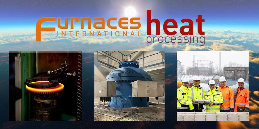
Heat Treat Today partners with two international publications to deliver the latest news, tech tips, and cutting-edge articles that will serve our audience – manufacturers with in-house heat treat. Furnaces International, a Quartz Business Media publication, primarily serves the English-speaking globe, and heat-processing, a Vulkan-Verlag GmbH publication, serves mostly the European and Asian heat treat markets.


Press Hardening Prevents Part Deformation

Press hardening neccessary due to part deformation during the rapid cooling phase induced by quenching
Source: Thermi-Lyon

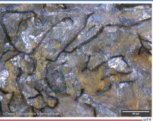
“Press hardening serves a very specific purpose: to prevent part deformation during the rapid cooling phase induced by quenching. This process improves the performance of steels by giving them a martensitic structure without the need for reworking. Designed for high volume production of parts with complex geometries, press hardening is both highly effective and economical….

This process was initially developed for automotive manufacturers, to process large series of parts with complex geometries. In fact, this method is perfectly suited to the processing of large numbers of parts on a production line: since the cooling cycle is automatically programmed, it can be repeated ad infinitum. What’s more, the circulation of quenching fluid around the part held in the press results in uniform, controlled cooling that can easily be reproduced many times over.”

READ MORE: Focus on Press Hardening and Its Advantages at heat-processing.com. 

HYBRIT Platforms Shift to Fossil-Free Steel

An electricity-based process gas heater for the hydrogen-based direct reduction process developed by HYBRIT (Hydrogen Breakthrough Ironmaking Technology)
Source: Kanthal

“Launched in 2016 as a joint venture owned by SSAB, LKAB, and Vattenfall, with support from the Swedish Energy Agency, HYBRIT aims to create the world’s first fossil-free, ore-based steel with renewable electricity and green hydrogen.

This involves shifting from coal-powered blast furnaces that use coal as a reduction medium to a direct reduction process using hydrogen produced via renewable energy. The first HYBRIT pilot plant in Luleå, Sweden, began operations in 2020, with commercial-scale production targeted by 2027.

Kanthal is proud to have contributed to HYBRIT’s groundbreaking journey by developing an electricity-based process gas heater for the hydrogen-based direct reduction process under the name Prothal®. This project showcased the feasibility of fossil-free industrial heating solutions and laid the groundwork for scaling up these technologies to meet the steel industry’s future needs.”

READ MORE:Innovations by Kanthal Drive the HYBRIT Revolution for Fossil-Free Steelat heat-processing.com

Largest Green Hydrogen Production Facility Underway

From left: Andrea Prevedello, Global Director Project Management of Green Hydrogen, at ANDRITZ; Walther Hartl, Project Manager of Electrolysis, at ANDRITZ; Sami Pelkonen, Executive Vice President of Green Hydrogen, at ANDRITZ; Gerd Baresch, Managing Director of the Technical Division, SZFG; Thorsten Hinrichs, Head of Pipeline Infrastructure, SZFG
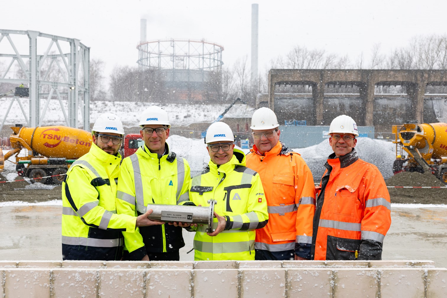
Source: Andritz Group

“On February 12, 2025, the cornerstone was laid for one of the largest production plants for green hydrogen in the whole of Europe.

[Beginning in] 2026, the plant will generate around 9,000 tons of green hydrogen a year to be used for the production of carbon-reduced steel. This will mark the start of the industrial use of hydrogen in SALCOS®-Salzgitter low CO2 steelmaking. SALCOS® is aiming for virtually carbon-free steel production. The 100 MW electrolysis plant will be supplied on an EPC basis by the international technology company ANDRITZ, using the pressurized alkaline electrolysis technology of HydrogenPro.”

READ MORE: SALCOS®: Cornerstone Laid for the Production of Green Hydrogenat heat-processing.com


Find Heat Treating Products And Services When You Search On Heat Treat Buyers Guide.Com

News From Abroad: Initiatives, Processing for a Better World Read More »

Heat Treat Radio #112: Lunch & Learn: How To Use a Hardenability Chart  

In this episode of Heat Treat Radio, Doug Glenn discusses the hardenability of materials with guest Michael Mouilleseaux, general manager at Erie Steel LTD. Michael walks us through how to interpret hardenability charts and provides detailed insights on reading these charts, including addressing the importance of understanding the nuances of complicated part geometry. 

Below, you can watch the video, listen to the podcast by clicking on the audio play button, or read an edited transcript.


The following transcript has been edited for your reading enjoyment.

Understanding a Hardenability Chart (01:59)

Doug Glenn: What I’d like to do is talk through this chart and learn how to read this a little bit better. And I’d like to ask questions about it because I’m not familiar with this, and I’m sure there are going to be some listeners and viewers who aren’t familiar with it. This will be just a quick tutorial on how to read these charts.

Go to the upper, right-hand corner. First off, SAE 4320H is the grade of the steel that we’re talking about?

The Heat Treat Lunch & Learn crew: Doug Glenn, Publisher of Heat Treat Today; Michael Mouilleseaux, General Manager at Erie Steel LTD.; Bethany Leone, Managing Editor of Heat Treat Today
Use this chart to follow along with the conversation.
Source of chart: Erie Steel, Ltd.

Michael Mouilleseaux: Correct.

Doug Glenn: Then the table right below that you’ve got percentage C (carbon). Is Mn manganese?

Michael Mouilleseaux: Manganese.

Doug Glenn: Thank you very much. Silicon, nickel, chrome, moly. My question is about those ranges. Is this basically saying the percentage carbon on the far left in 4320H goes anywhere from 0.17–0.23?

Michael Mouilleseaux: That is correct.

Doug Glenn: Okay. So that’s variability right there. All of those are basically telling you what the ranges are in those alloys in this grade of steel?

Michael Mouilleseaux: That is correct.

Doug Glenn: Then you go down to the top columns of this table below, and it says “Approximate diameter of rounds with same as quenched HRC in inches.” Right?

Approximate diameter of rounds with same as quenched HRC in inches
Source: Erie Steel, Ltd.

Michael Mouilleseaux: Yeah. Essentially, the first three rows are for water quenching. And the bottom three are for oil quenching.

Doug Glenn: If you go over to the second major column called “Location in round,” what’s the size of the round we’re working on here?

Michael Mouilleseaux: It can vary. Go down to where it says, “Mild Oil Quench,” then left to “Surface,” then left then go to “2 inches.” Then, go straight down to the bottom, and that’s approximately J5. So, the “Distance from Quenched End — Sixteenths of an Inch” is Jominy position 5.

Michael Mouilleseaux: If you go to Jominy position 5 on the left-hand chart, you can see the hardness limits for that; the maximum is Rockwell C 41, and the minimum is Rockwell C 29. So, the chemistry can vary provided the hardenability at J5 is 29–41.

Doug Glenn: That’s the acceptable range?

Michael Mouilleseaux: That’s the acceptable range. That’s one way of looking at it. The chemistry would allow you to do that.

Now, go back to the chart on the right-hand side and to “Surface,” move down one row to “¾ radius from center,” and go left to two inches. Moving down from there you see that is Jominy position 8. So, the surface of a two-inch round is Jominy position 5, and the ¾ radius is Jominy position 8.

If you go to the hardness chart on the left-hand side, that says that if you had a two-inch round of 4320H, and it was oil quenched, and you check the hardness at ¾ radius, then the expectation is that it would be 23–34.

Now, go back to the same chart that we were just at, and go to the “Center” row of “Mild oil quench.” Continue left to two inches, and that’s J12. Go back to the left-hand chart, and J12 is 20–29 in the center of the part.

So, the surface of the part could be 41, ¾ radius, center of the part would be 34, and the center of the part would be 29.And that would all meet the criteria.

Doug Glenn: The maximum for J5 would be 41.But at J12 you could get a 20 in the middle.

Michael Mouilleseaux: Right. That is one way to look at this chart. But there is another way.

Notice that it says “rounds.”There are some nuances to having flats and rectangles because, if you think about it, for the cross-sectional area of a rectangle, the hardenability is going to be determined by the direction that it is thinnest, not by the direction that it is thickest.

Take a gear tooth, for example: in the chart that we just made up the gear teeth, the root of the gear was about a half inch, just slightly more; and if we go to this same chart, go to “Center” of “Mild oil quench,” and then go to a “0.5 inch,” and when you go straight down, that’s the J3.

Is a gear necessarily a round? Of course, the answer to that is no. So, in complex shapes you can use this data, but you have to interpolate it in order to understand it.

To some extent, the first time you run this, you’re going to say, “I have a gear, and the root is a half inch across. And I know that the J3 is 40. And I’ll run this part, and I’ll section it and I’ll measure it and it’s 40. And I’ll say that’s a good approximation of that.” And experientially, you build confidence in this, that is, it’s your operation, your quenching operation, and your components. It allows you to interpolate these, and they become extremely useful.

So, is it definitive? No. Is it useful? Yes.

Doug Glenn: It gives you a ballpark, right? I mean, it’s giving you something, maybe guardrails.

Michael Mouilleseaux: It gives you a ballpark; it gives you guardrails. And I can tell you that after having run gear product in the same equipment for ten years, I can say that it’s definitive. I can say that if I have this hardenability, and I get this hardenability number for this heat, and these gears are made from this heat of steel, and it has a J3 of 42. If I’m at 38, I know something is going on other than just hardenability. And, at that point, I would suspect my heat treat operation.

Doug Glenn: Yeah. I have one more question about this chart: On the bottom right part of the graph there are two plot lines on there. What do those represent? I was thinking one represented the water quench and the bottom one represents the oil quench.

Plot lines representing maximum hardenability and minimum hardenability
Source: Erie Steel, Ltd.

Michael Mouilleseaux: The top one represents the maximum hardenability. And the lower the lower one represents the minimum hardenability.

Doug Glenn: That’s your band. Okay. Those are basically your values over on the left-hand side then. Very good.

I don’t know about you, but I found that helpful. I really didn’t ever know how to read these tables. So, maybe someone else will find that useful. Thanks, Michael. I appreciate your expertise.

Michael Mouilleseaux: It’s been my pleasure.

About The Guest

Michael Mouilleseaux
General Manager at Erie Steel, Ltd.
Sourced from the author

Michael Mouilleseaux is general manager at Erie Steel LTD. Mike has been at Erie Steel in Toledo, OH, since 2006 with previous metallurgical experience at New Process Gear in Syracuse, NY, and as the Director of Technology in Marketing at FPM Heat Treating LLC in Elk Grove, IL. Having graduated from the University of Michigan with a degree in Metallurgical Engineering, Mike has proved his expertise in the field of heat treat, co-presenting at the 2019 Heat Treat show and currently serving on the Board of Trustees at the Metal Treating Institute.

Contact Mike at mmouilleseaux@erie.com.


Search Heat Treat Equipment And Service Providers On Heat Treat Buyers Guide.Com


Heat Treat Radio #112: Lunch & Learn: How To Use a Hardenability Chart   Read More »

Deep Cryogenics 101

OCHeat treaters often target gas nitriding and carburizing as key additions to their facility, but sometimes they miss a low-cost opportunity for big wear improvement called Deep Cryogenic Treatment. What is it and could it be a game changer for your business?

This Technical Tuesday feature was written by Jack Cahn, president of Deep Cryogenics International and was first published in Heat Treat Today's May 2022 Induction Heating print edition.


Jack Cahn
President
Deep Cryogenics International
Source: Deep Cryogenics International

Benefits

Deep Cryogenic Treatment (DCT) is a thermal process which provides 20–70% increased wear life, 10–20% increased ultimate tensile strength (UTS )/yield strength, and up to a 30% reduction in corrosion effect (Figures 1 & 2). Unlike case hardening or surface coating there is no part distortion, and cryogenically treated items are not prone to fatigue cracking. Whereas nitriding leaves a recast or white layer, DCT does not. Unlike all three processes, dissimilar materials (such as ferrous and non-ferrous) with varying geometric thicknesses can be treated together to increase mechanical and chemical properties. DCT can also be combined with gas nitriding to yield fine precipitates of carbo-nitrides and thru-core eta carbides — combining the best of diffusion and quenching with a diffusion-less thermo-kinetic process (Figure 3). DCT offers permanent, non-reversible wear improvement with no degradation over time.

(Left) Figure 1. Yield strength improvement;
(Right) Figure 2. Corrosion reduction
Source: Deep Cryogenics International

Many knife and tool steel manufacturers recommend the use of DCT after austenitizing and quenching but before tempering. It is standard industry practice to employ DCT to increase the wear life of D2, H13, S7, 440C, and several mold steels used in the plastic injection, stamping, and forging die industries.

DCT is also one of the lowest cost thermal processes available to heat treaters who already support exothermic and endothermic processes using onsite liquid nitrogen. Environmentally, DCT is neutral: it improves metallic wear life but leaves behind no chemicals, waste, or cleanup and requires no flammable, hazardous, or explosive gases. Fifteen of the 20 largest commercial heat treaters in North America promote their own DCT services and hundreds more have small DCT equipment.

Figure 3. Wear resistant carbides
Source: Deep Cryogenics International

How It Works

The DCT process usually follows austenitizing and quenching and is, effectively, a continuation of the quench process below martensite start and finish temperature. Items are placed in a specially designed chamber and slowly cooled from ambient to approximately -320°F (-195.5°C) over six to eight hours and then maintained in a dry, nitrogen gas environment for 8–30 hours before slowly returning to ambient — followed by 1–3 tempering steps. Round, vacuum-insulated processors use less liquid nitrogen (LN2 ) than rectangular chambers and can temper heavy items in-situ (Figure 4).

Figure 6. 14,000 lbs of Mn crusher cone mantles in the 36K
Source: Deep Cryogenics International

DCT is a diffusion-less thermal process that causes the transformation of retained austenite into martensite without embrittlement and the precipitation of primary and secondary eta carbides. With a low enough temperature and soak time there is a phase change from face-centered cubic (FCC) into body-centered cubic (BCC) or hexagonal close packed (HCP) slip systems. DCT relieves both cyclic and imposed stresses in metals caused by heat treating or manufacturing, further reducing the migration of crystalline defects such as stacking faults, dislocations, inclusions, and vacancies (Figures 5a & 5b). With the reduction in defect migration comes a reduction in interatomic spacing — directly lowering fatigue crack nucleation and propagation.

The process is effective on castings, forgings, additive manufactured, and fully machined items because DCT is a through-material process — maintaining wear protection long after surface coatings and case hardening have eroded. With the recent availability of industrial DCT equipment capable of treating parts 8’ x 8’ x 20’ and up to 30,000 lbs., the process now can be used on large turbine, oil and gas, and mining components previously cast too large for DCT (Figure 6).

So, with all these benefits, why has this process been so overlooked and underused?

Early Adoption and Stall

In the 1980s, heat treaters accepted cold treatment (-80°F) to reduce retained austenite and, later, shallow cryogenic treatment (-140°F to -240°F) to reduce residual stress. However, a lack of DCT test labs that could scientifically demonstrate DCT wear benefits, no large capacity DCT equipment available, and no DCT-specific ASTM test methods were key barriers hampering market growth. Unfortunately, DCT doesn’t show increased wear improvement using the universally adopted Rockwell hardness test ASTM E18-20. Without a specific ASTM test to validate process improvement and no suppliers of large size DCT chambers to complement the existing car bottom industrial furnaces, few heat treaters readily adopted DCT. The DCT chamber frequently sat unused in a corner of the shop.

The Current Opportunity

The key breakthrough for the DCT technology has been the evolution of industrial size equipment. Built and prototyped by Deep Cryogenics International in late 2021, the 36K offers heat treaters a new means to expand their service offerings and new capacity to DCT large parts. Since the 36K cryogenically treats at -320°F but also tempers to 350°F, the entire process (including post-DCT tempering) can be performed in one chamber. No longer will capacity be a technology limiter.

A new business model has also changed the DCT industry: low-cost leasing. By removing the high cost of capital purchase, Deep Cryogenics International’s captive leasing program offers heat treaters access to industrial scale DCT, coupled to an on-site liquid nitrogen generator and a 3,000-gallon storage dewar. Now LN2 can be generated on site at less than bulk supplied gas — dropping the “all in” cost of DCT to less than $0.20 per pound.

Figure 7. DCI VP Linda Williams next to the 36K
Source: Deep Cryogenics International

Lloyd’s Register is currently qualifying both the 36K and the DCT technology using a new approach to a recognized test standard — ASTM E2860 Residual Stress testing using X-ray diffraction. This non-destructive test method will positively identify DC-treated parts and correlate a level of improvement based on the drop in residual stress.

2022 will be a big year for DCT with a lot of firsts: large capacity equipment, a captive leasing program, and industry test and certification.

About the Author: Jack Cahn is president of Deep Cryogenics International — a manufacturer of DCT equipment with an in house DCT research lab. His 25-year background in DCT includes design and development of DCT procedures used in scientific, military, energy, and mining applications. He is the author of several patents, certification marks, and research papers. DCI will be opening a DCT demonstration facility in southern Alberta in June 2022.

Contact Jack Cahn: 902-329-5466 or jack@deepcryogenics.com


Find heat treating products and services when you search on Heat Treat Buyers Guide.com


Deep Cryogenics 101 Read More »

Skip to content