The Heat Treat Doctor® has returned to offer sage advice to Heat Treat Today readers and to answer your questions about heat treating, brazing, sintering, and other types of thermal treatments as well as questions on metallurgy, equipment, and process-related issues.
This informative piece was first released in Heat Treat Today’sFebruary 2025 Air/Atmosphere Furnace Systems print edition.
People often ask two fundamental questions related to normalizing. First, is it necessary? Second, just what and how important is a “still air” cool to the end result? Let’s learn more.
Why Normalize?
Contact us with your Reader Feedback!
Normalizing is typically performed for one or more of the following reasons:
To improve machinability
To improve dimensional stability
To produce a homogeneous microstructure
To reduce banding
To improve ductility
To modify and/or refine the grain structure
To provide a more consistent response when hardening or case hardening
For example, many gear blanks are normalized prior to machining so that during subsequent hardening or case hardening dimensional changes such as growth, shrinkage, or warpage will be better controlled.
Normalizing imparts hardness and strength to both cast iron and steel components. In addition, normalizing helps reduce internal stresses induced by such operations as forging, casting, machining, forming or welding. Normalizing also improves chemical non-homogeneity, improves response to heat treatment (e.g., hardening), and enhances dimensional stability by imparting into the component part a “thermal memory” for subsequent lower temperature processes. Parts that require maximum toughness and those subjected to impact are often normalized. When large cross sections are normalized, they are also tempered to further reduce stress and more closely control mechanical properties.
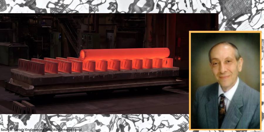
Large paper roll normalized in a car bottom furnace and cooled (due to its mass) using the assistance of a floor fan.
Soak periods for normalizing are typically one hour per inch of cross-sectional area but not less than two hours at temperature. It is important to remember that the mass of the part or the workload can have a significant influence on the cooling rate and thus on the final microstructure. Thin pieces cool faster and are harder after normalizing than thicker ones. By contrast, after furnace cooling in an annealing process, the hardness of the thin and thicker sections is usually about the same.
Micrograph of medium-carbon AISI/SAE 1040 steel showing ferrite grains (white etching constituent) and pearlite (dark etching constituent). Etched in 4% picral followed by 2% nital. (Bramfitt and Benscoter, 2002, p. 4. Reprinted with permission of ASM International. All rights reserved.)
When people think of normalizing, they often relate it to a microstructure consisting primarily of pearlite and ferrite. However, normalized microstructures can vary and combinations of ferrite, pearlite, bainite, and even martensite for a given alloy grade are not uncommon. The resultant microstructure depends on a multitude of factors including, but not limited to, material composition, part geometry, part section size, part mass, and cooling rate (affected by multiple factors). It is important to remember that the microstructure achieved by any given process sequence may or may not be desirable depending on the design and function of the component part.
The microstructures produced by normalizing can be predicted using appropriate continuous cooling transformation diagrams and this will be the subject of a subsequent “Ask The Heat Treat Doctor” column.
In this writer’s eyes, industry best practice would be to specify the desired microstructure, hardness, and mechanical properties resulting from the normalizing operation. Process parameters can then be established, and testing performed (initially and over time) to confirm/verify results.
In many cases, the failure of the normalizing process to achieve the desired outcome centers around the lack of specificity (e.g., engineering drawing requirements, metallurgical and mechanical property call outs, testing/verification practices, and quality assurance measures). Failure to specify the required microstructure and mechanical properties/characteristics can lead to assumptions on the part of the heat treater, which may or may not influence the end result.
“Normalizing is the heat treatment that is produced by austenitizing and air cooling, to produce uniform, fine ferrite/pearlite microstructures in steel … In light sections, especially in alloy hardenable steels, air cooling may be rapid enough to form bainite or martensite instead of ferrite and pearlite.”
What Is Normalizing?
The normalizing process is often characterized in the following way: “Properly normalized parts follow several simple guidelines, which include heating uniformly to temperature and to a temperature high enough to ensure complete transformation to austenite; soaking at austenitizing temperature long enough to achieve uniform temperature throughout the part mass; and cooling in a uniform manner, typically in still air” (Herring, 2014).
It is also important to remember that normalizing is a long-established heat treatment practice. As far back as 1935, Grossmann and Bain wrote:
Normalizing is the name applied to a heat treatment in which the steel is heated above its critical range (that is, heated to make it wholly austenitic) and is then allowed to cool in air.
Since this is one specific form of heat treatment, it will be realized that the structure and mechanical properties resulting from the normalizing treatment will depend not only on the precise composition of the steel but also on the precise way in which the cooling is carried out.
The term ‘normalizing’ is generally applied to any cooling ‘in air.’ But in reality, this may cover a wide range of cooling conditions, from a single small bar cooled in air (which is fairly rapid cooling) to that of a large number of forgings piled together on a forge shop floor … which is a rather slow cool, approaching an anneal. The resulting properties in the two cases are quite different.
In plain carbon steels and in steel having a small alloy content, the air-cooled (normalized) structure is usually pearlite and ferrite or pearlite alone … More rapid cooling gives fine pearlite, which is harder; slow cooling gives coarse pearlite, which is soft. In some few alloy steels, the normalized structure in part may be bainite.
The hardness of normalized steels will usually range from about 150 to 350 Brinell (10 to 35 Rockwell C), depending on the size of the piece, its composition and hardening characteristics.
Importance of Defining Cooling Rate
In 2005, Krauss underscored the importance of defining cooling rate when he wrote: “Air cooling associated with normalizing produces a range of cooling rates depending on section size [and to some extent, load mass]. Heavier sections [and large loads] air cool at much lower cooling rates than do light sections because of the added time required for thermal conductivity to lower temperatures of central portions of the workpiece.”
Microstructures Created by Normalizing
The microstructural constituents produced by normalizing for a particular steel grade can be ferrite, pearlite, bainite, or martensite. The desired microstructure from normalizing adds an important cautionary note, as addressed by Krauss in STEELS (1990 and 2005), namely: “Normalizing is the heat treatment that is produced by austenitizing and air cooling, to produce uniform, fine ferrite/pearlite microstructures in steel … In light sections, especially in alloy hardenable steels, air cooling may be rapid enough to form bainite or martensite instead of ferrite and pearlite.”
Next time: We define a “still air” cool and look at the state of normalizing in North America.
Practical Data for Metallurgists, 17th ed. TimkenSteel.
Totten, George E., ed. Steel Heat Treatment Handbook, vol. 2, 2nd ed., CRC Press, 2007. 612-613.
About the Author
Dan Herring “The Heat Treat Doctor” The HERRING GROUP, Inc.
Dan Herring has been in the industry for over 50 years and has gained vast experience in fields that include materials science, engineering, metallurgy, new product research, and many other areas. He is the author of six books and over 700 technical articles.
As this author notes, “Aluminum’s unique blend of lightness, strength, and purity makes it indispensable across various industries.” Especially for aerospace components, bonding aluminum alloy materials to achieve premium structural integrity is essential to keep pace with the demands of new component designs.
In this Technical Tuesday installment, Horst-Gunter Leng, product manager at PVA TePla discusses recent developments in diffusion bonding technology with increased bonding speed of aluminum and aluminum alloys by up to 50%, decreased energy use by 30%, and improved quality.
This informative piece was first released inHeat Treat Today’sFebruary 2025 Air/Atmosphere Furnace Systems print edition.
Background: Aluminum Innovations and Joining
Aluminum, and its broad family of alloys, is prized as a lightweight metal with high purity, strong structural integrity, high electrical and thermal conductivity, corrosion resistance, and a malleability that makes it easy to shape. In aerospace, its high strength-to-weight ratio is crucial for structural components. For semiconductor equipment, aluminum enables the fabrication of intricate, contamination free channels essential for gas and fluid flow, avoiding the impurities inherent in traditional joining methods like brazing or welding.
Many developments in high demand or high quality industrial sectors involve aluminum as one or more of the layers of metals that are bonded. Diffusion bonding is a joining method used to achieve a high-purity interface when two similar or dissimilar metals require superior structural integrity and a traditional brazing approach fails to yield optimum results. The process involves applying high temperature and pressure to metals mated together in a hot press, which causes the atoms on solid metallic surfaces to intersperse and bond, typically (but not exclusively) in vacuum furnaces.
Aluminum’s compatibility with diffusion bonding has allowed for the creation of complex cooling channels in high-power electronics, injection molds, and specialized heat exchangers — designs often impossible to achieve through conventional machining.
Unfortunately, the thermal conductivity characteristics of aluminum present a challenge for the traditional diffusion bonding process, which involves the application of radiant heat into the metal layers while in a vacuum furnace.
This article explores a new bonding technology that overcomes this challenge with a conductive heating method which more rapidly reaches bonding temperature.
Traditional Diffusion Bonding: Challenges with Aluminum
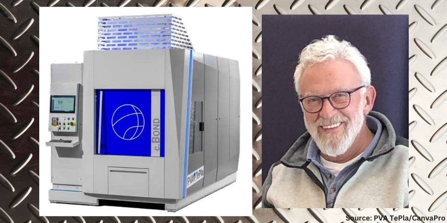
Figure 1. Depiction of a c.BOND machine
In the traditional diffusion bonding process, a vacuum furnace provides radiant heat to the surface of the part. Subsequently, the heat is conducted through the assembly and transmitted to the faying surface (i.e., surfaces in contact at the joint) where required. Aluminum excels at conducting heat, particularly at lower temperatures, making it ideal for applications requiring efficient heat dissipation, such as in electronics and automotive components. However, when radiation is the dominant form of heat transfer, particularly at relatively lower temperatures in vacuum below 1112°F (600°C), aluminum’s thermal conductivity is time consuming.
Aluminum’s high reflectivity poses a challenge in traditional diffusion bonding. It is like trying to heat a mirror with a spotlight — the energy is reflected away instead of being absorbed into the material using the traditional diffusion bonding process.
Diffusion bonding of aluminum requires superior temperature control throughout the process. To prevent overheating of the load, slow heating rates traditionally are applied, leading to long process times.
In addition, aluminum alloys have a narrow processing temperature range for successful bonding. When temperatures fall outside that critical temperature band, a poor bond is produced.
New Diffusion Solution with Conductive Heating
To overcome the existing challenges of bonding aluminum, a global manufacturer of both industrial furnaces and PulsPlasma nitriding systems alongside its partner initiated an extensive development program. The result was an innovative solution: integrating heating elements directly into the press platens. This approach speeds up the bonding process and significantly reduce enhances efficiency by directly transferring heat to the aluminum components.
The culmination of this research and development is the c.BOND machine. The machine features a combination of direct conduction heating through the top and bottom platens, which are in contact with the assembly. This design ensures bi-directional homogenous heating and more precise temperature at the bonding interface where it is required.
The machine utilizes a hot-press tool with advanced software and feedback sensors to achieve micrometer-precise pressure control across the entire component surface. This ensures uniform bonding over large areas. Furthermore, the system allows for selective heating of specific areas, preventing unnecessary heat exposure to other parts of the component.
The high-vacuum atmosphere within the chamber eliminates contamination and prevents voids in the bonded joint.
With this machine, the time to heat the part to the ideal temperature for bonding is cut in half compared to traditional radiant heating. With less processing time required, the energy requirements are reduced by up to 30% as well. Multilayer stacking is also possible, which can further increase productivity.
With the size of components continually getting smaller in sectors like semiconductors and electronics, controlling the amount of time, and by extension heat, introduced into the part becomes more critical.
Horst-Gunter Leng
The technology demonstrates significant quality improvement of bonded aluminum components. It improves temperature homogeneity in the load by 70%, enhancing bonding across the entire surface. This method also improves the parallelism of parts by 50%, which enhances the accuracy of geometric dimensions, tolerances and product specifications.
As this new machine is commercially available for high-volume production, heat treaters can leverage this furnace technology alongside another unique feature that is incorporated within the system: proprietary automatic bonding software (ABP).
With the automatic bonding software, after parts can be placed in the furnace and a few parameters (such as the size of the bonding area) input, the software automatically calculates the optimum processing parameters. No specific diffusion bonding knowledge from the operator is required. The recipes can be modified according to the type of material being bonded, the thickness of the material, its surfaces and other factors. During the process, the software continuously monitors the process in real time and adjusts parameters accordingly.
Real-World Applications
A unit was installed at a national research facility in Germany, The Günter Köhler Institute for Joining Technology and Materials Testing (ifw Jena), an independent, non-university industrial research institution that conducts research in diffusion bonding, additive manufacturing, brazing, welding, laser processing, material science and other forms of bonding.
The system is compact, requires minimal maintenance, and enables high-volume production of aluminum components for diverse industries. Its benefits are being realized in aerospace, where it creates lightweight yet strong aircraft components. In the semiconductor industry, it provides a cleaner alternative to brazing, eliminating the risk of solder contamination. There is also growing demand for diffusion-bonded aluminum heat sinks, crucial for cooling high-power silicon carbide (SiC) electronics.
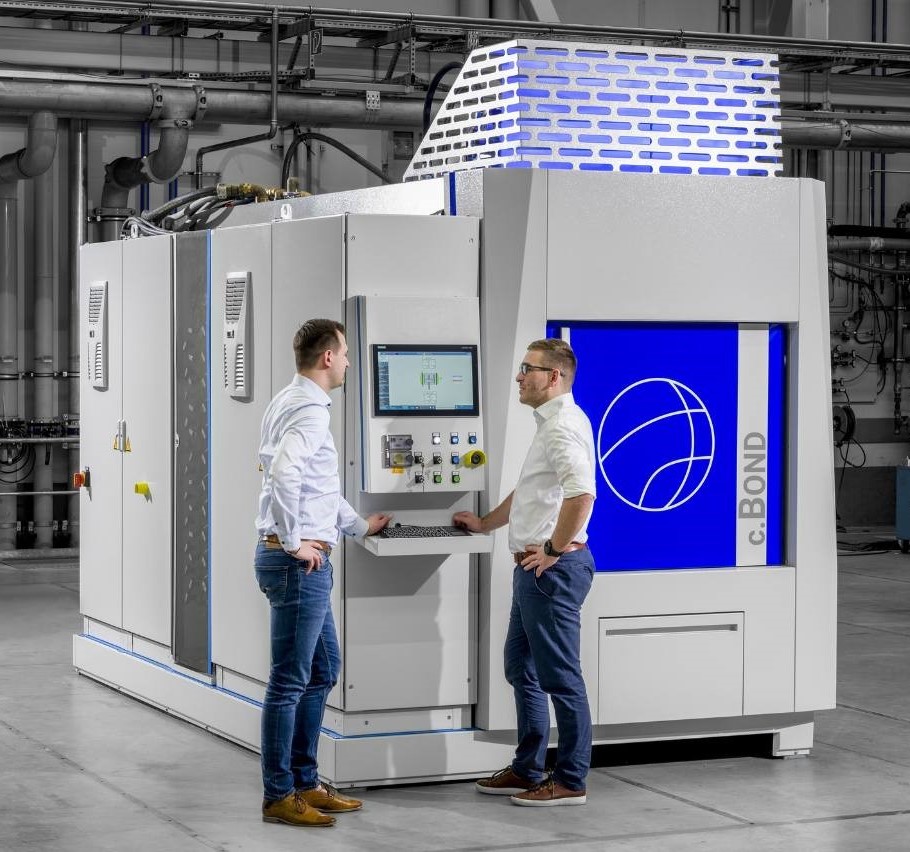
Figure 2. Example of the c.BOND machine
Diffusion bonding also has applications for conformal cooling. The concept is to bond layers of sheet metal that contain machined channel/microchannel structures. When combined, the channels provide a path for heat dissipation. Current applications include power electronics for effective heat management and rapid cooling of molds utilized in injection and blow molding processes.
With the size of components continually getting smaller in sectors like semiconductors and electronics, controlling the amount of time, and by extension heat, introduced into the part becomes more critical.
As the features of the internal channels become more miniaturized, it becomes even more important to control the heating during the diffusion bonding process to avoid any distortion in the part. Shortening the cycle time means introducing less heat into the part. This will facilitate creating parts with conformal cooling channels that have finer and finer features.
As mentioned earlier in this article, diffusion bonding is increasingly valuable for joining dissimilar metals, such as aluminum to steel or titanium. This allows engineers to design components and assemblies with the best properties of each metal. For example, one metal might offer superior corrosion resistance while the other provides greater strength. This “packaging” of dissimilar metals opens up new possibilities in design, particularly for overall weight reduction of design and enhancing performance in challenging environments.
When joining dissimilar surfaces, a liquid-phase diffusion bonding process is utilized, particularly when the bonding interface extends beyond R&D-sized samples. This often involves an interlayer of an alloy that typically melts at the faying surfaces. When the interlayer includes aluminum, the machine can deliver controlled heat to increase the bonding speed.
Conclusion
This new approach to diffusion bonding offers an alternative to the traditional method by circumventing the slow process of radiant heating structural assemblies in a vacuum environment. Although the technology in c.BOND is designed to improve the diffusion bonding of aluminum, it can be modified to the specific needs of the client and customized for the alloy, including copper, an alloy that has many applications in specialized heat exchanger and products used in the microelectronics industry. PVA TePla is exploring options to modify the machine to achieve even higher temperatures above the current maximum of 1472°F (800°C).
As diffusion bonding of aluminum gains importance across industries, contract manufacturers and design engineers must embrace the latest advancements to remain competitive. By adopting fast, energy efficient diffusion bonding technologies for aluminum and other materials, they can unlock higher production volumes, reduce costs, improve or achieve global sustainability targets, and increase profitability.
About the Author:
Horst-Gunter Leng Product Manager PVA TePla
Horst-Gunter Leng is the product manager for PVA TePla, a global manufacturer of industrial furnaces and PulsPlasma nitriding systems.
The Heat Treat Doctor® has returned to offer sage advice to Heat Treat Today readers and to answer your questions about heat treating, brazing, sintering, and other types of thermal treatments as well as questions on metallurgy, equipment, and process-related issues.
This informative piece was first released in Heat Treat Today’sJanuary 2025 Technologies to Watch print edition.
As a very young engineer, I vividly recall our company president had a statue of a three-headed elephant in his office. One head faced forward, one faced slightly to the right, one faced slightly to the left. The moral: looking backwards is not the path forward! Let’s learn more about what the heat treatment industry will look like by the middle of this century.
The Market
A number of market studies and economic forecast models suggest that the global heat treatment market will grow to between 130–150 billion U.S. dollars by no later than 2030 and to around 200–220 billion U.S. dollars by 2040, barring another significant or sustained global economic event. These forecasts assume several minor downturns in the economy of various countries and in manufacturing segments due to economic and geopolitical factors in the coming decades.
Heat Treatment Market Shift
Contact us with your Reader Feedback!
The most significant and fundamental shift that is and will continue is in the makeup of the heat treatment equipment segment of the North American market. What began in the late 1990s and early 2000s as a transition from older, long-established practices and processes to equipment capable of meeting the rapidly evolving demands of technological innovation will continue. Standardization (for cost containment), changes in manufacturing methods and methodologies, and environmental considerations are also fueling this change.
A demand for higher performance products, end-of-life expectations (in some but not all products), an emphasis on systems with single-piece flow or small batch productivity are just a few examples of this change. Other factors such as equipment obsolescence, the need for even higher manufacturing efficiencies, long term operator health and safety concerns, predictive (as opposed to preventative) maintenance, and adaptation to both the speed at which the manufacturing landscape is changing and the type of flexible equipment/processes reinforce these conclusions.
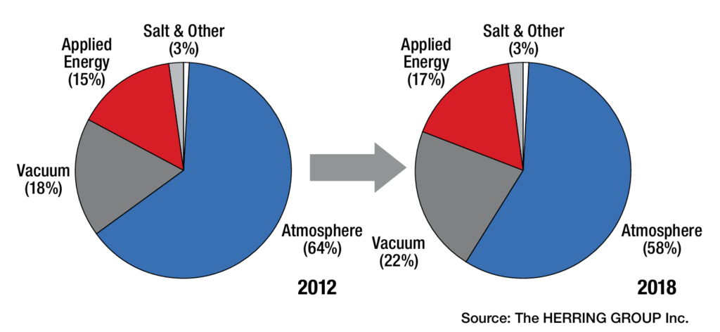
From an equipment standpoint, vacuum furnaces and applied energy systems are and will continue to experience rapid growth at the expense of more traditional atmosphere furnaces. Safety, open flames and emissions of any kind (NOx, CO2, particulates) are driving this change. As such, the dramatic reduction and control of greenhouse gases and the cooling of our planet by the mid-century will be metamorphic. This trend is not only expected to continue but to accelerate (Figures 1–2).
Figure 1. North American Industry by Equipment Segment, 2012–2018 (see Herring, Atmosphere Heat Treatment, Vol. 1, 2014)
For example, the driving force behind the development, use and integration of vacuum technology into manufacturing is not only due to the fact that it is lean, green, and agile, but also that vacuum technology best addresses the identified needs of the heat treatment industry, namely:
Energy efficient equipment
Processing with minimal part distortion
Optimization of heat treatment processes (especially diffusion-related processes)
Environmentally friendly by-products and emissions
Adaptability/flexibility for new and advanced materials
Process controls incorporating intelligent sensors
Designs based on heat treat modeling and simulation
Equipment/process integration into manufacturing
Change — Its Pace and Form
A paradigm shift in the workforce has occurred, transitioning to a vastly more mobile and younger group of individuals relying on the growing role of automation and communication in manufacturing. This shift is principally responsible for accelerating the pace of change in the heat treatment industry, from what has traditionally been a slow moving and slow-to-adapt industry, to one capable of meeting the need for rapid deployment of new products and one that keeps pace with technological innovations.
Moving forward, equipment manufacturers and suppliers to the industry will continue to look at product standardization to maximize profitability, thus driving the industry to “cookie cutter” solutions or, in a diametrically opposite philosophy, looking to provide highly customized solutions, often with risk factors incorporated into the pricing as specialized solutions with high profit margins to application-specific needs.
Figure 2. North American Industry by Equipment Segment, 2024–2035 (see Herring, Atmosphere Heat Treatment, Vol. 1, 2014)
Technology/Innovation Drivers and Industry Trends
Heat treatment will always be a core manufacturing competency, and as such, decisions will continue to be made to either heat treat in-house or outsource to commercial heat treatment shops. It is significant that the percentage of manufacturers with in-house heat treat departments (80–85%) to commercial (10–15%) heat treat shops hasn’t really changed in the last six decades! The consolidation of companies is a trend that is expected to continue.
What is more prevalent today than ever is the tremendous pressure being exerted on manufacturing from senior management to increase product velocity and lower unit cost. While recalls seem to be a way of life these days, product liability and consume demands for product performance are forcing change, even in the most extreme applications.
As a result, the most identifiable trends in today’s North American heat treatment industry are:
Growing the manufacturing portion (percentage) of GDP through mobility and adaptability, coupled with more sophisticated and higher paying jobs
Lowering product unit cost through technology adaptation
Obsoleting older equipment and technologies and replacing them with innovative new and/or high productivity heat treatment systems. Examples include:
New materials development allowing for different processing methods and/or lower temperature heat treatments while maintaining environmentally friendly equipment and processes
Transition of carburizing/ carbonitriding from atmosphere to low pressure vacuum processes with either oil or high-pressure gas quenching, or both
Use of single-piece heating and quenching of parts and/or small (versus large) batch processing to improve product velocity
Changes in product materials and/or designs to allow more low temperature atmosphere treatments (e.g., nitriding, nitrocarburizing)
Use of advanced quenching techniques and quenching technologies to better manage distortion
Implementing artificial intelligence-based modeling and simulation software capable of equipment control and process optimization
Implementing the next generation of intelligent sensors, real-time data collection methods and analytics (including cloud-based computing)
Changing the focus of companies from “generalization” toward “specialization” with respect to products, services, processes (proprietary or unique) and new or innovative technologies to capture greater market share or present opportunities to generate higher profit margins
Accelerating the implementation of lean manufacturing strategies and applying these strategies to heat treatment:
Eliminate high labor costs (via automation and controls), simplify operations (i.e., reduce the number of manufacturing steps), and adopt “build to order” strategies.
Conservation of energy, on-demand part production, shortening of process cycles, and the move toward smaller lot sizes is the order of the day.
Continuing the transition from heat treatment departments to integrated manufacturing cells
In Summary
It is, and will be for decades to come, a truly magical time in the heat treatment industry. The slow-moving, plodding, three-headed elephant has been replaced by a lean and agile animal — technology. This will not only ensure a greener workplace but an environment of innovation for future generations. And as I am fond of saying about the future, there’s “magic in the aire!”
References
ASM International, Vision 2020. 1999.
Herring, Daniel H. “Esoteric Heat Treatment Industry Critique: 2019 and Beyond.” Industrial Heating, January 2019.
Herring, Daniel H. Atmosphere Heat Treatment, Volume 1. BNP Media, 2014.
Wolowiec-Koreka, Emilia. Carburising and Nitriding of Iron Alloys. Springer, 2024.
About the Author
Dan Herring “The Heat Treat Doctor” The HERRING GROUP, Inc.
Dan Herring has been in the industry for over 50 years and has gained vast experience in fields that include materials science, engineering, metallurgy, new product research, and many other areas. He is the author of six books and over 700 technical articles.
Industry experts agree: 2025 is a year of significant, high-tech developments. In this Technical Tuesday, hear from three heat treat industry consultants on current and incoming technological advances, from miniaturization and customization to artificial intelligence.
Michael Mouilleseaux, general manager at Erie Steel, Ltd, opens the discussion by asking what role AI has in a perfect world of heat treating; Thomas Wingens, president of Wingens Consultants, predicts six major technologies to look for in 2025; and Dan Herring, a.k.a. The Heat Treat Doctor® and owner of The HERRING GROUP, Inc., points out how the trend toward smaller is affecting the heat treat industry.
This informative piece was first released inHeat Treat Today’sJanuary 2025 Technologies To Watch in Heat Treating print edition.
AI’s Place in Heat Treating?
by Michael Mouilleseaux
The benefits of AI are purported to be the ability to reduce the time required to complete complex tasks, such as data analysis, while reducing human error and providing both unbiased decision making and data-driven system enhancements … and by the way, it can operate 24/7 without breaks!
Does AI have a place in heat treating?
Here’s what I would want my heat treat AI (HT AI) to be able to do with a gas-fired atmosphere furnace.
Combustion System:
My HT AI will continuously monitor the free oxygen of all the burners and keep them at a perfect ratio, thereby optimizing performance and gas consumption. It will track these changes and provide analysis of any trends that it “perceives,” so to speak.
My HT AI will continuously monitor combustion air pressure and message me in time to have the air filters changed before it affects performance. It will track this and provide historical and prescriptive information.
My HT AI will periodically perform a “tube check,” whereby it will shut off combustion in a tube and monitor the free oxygen, recognizing that any diminishment from “atmospheric” O2 levels indicate the potential of a tube leak. It will track this and provide analysis of any trends that it perceives.
My HT AI will track when system thermal stasis is achieved, monitor gas consumption for each discrete heat treat cycle, provide analysis of trends that it perceives, and recommend thermal cycle changes to optimize these cycles.
My HT AI will facilitate the optimization of the critical human assets in process engineering, product quality and equipment maintenance.”
Michael Mouilleseaux
Atmosphere Control System:
My HT AI will continuously monitor the atmosphere flows required to achieve the requirements for each heat treat cycle. It will track “atmosphere recovery” and provide analysis of any trends that it perceives (i.e., increased usage as a precursor to a furnace leak).
My HT AI will periodically perform a furnace check, whereby it compares the composition of the Endo gas in the furnace to that exiting the generator, providing a measure of furnace integrity. It will track this and provide analysis of any trends that it perceives.
My HT AI will confirm “tube check” data (see above) with atmosphere usage to evaluate its potential effects on process integrity and make actionable recommendations. It will track these incidents and provide analysis of any trends that it perceives.
My HT AI will provide assurance of system performance and actionable information.
Shoot for the Moon:
My HT AI will have the unique ability to integrate metallurgical results with process information and thereby provide the ability to optimize the heat treating process AND metallurgical results.
My HT AI will allow me to input material chemical and hardenability data and, by comparing actual results with the calculated, or prospective results, provide confirmation of the thermal and quenching segments of the process.
My HT AI will be able to correlate IGO results with furnace integrity checks (i.e., leaks) and over time establish hard limits for allowable leak rates.
My HT AI will be able to correlate actual retained austenite levels in carburized case with furnace carbon potential and make data-driven process modifications to optimize this.
My HT AI will be able to correlate the shape of the case depth curve with the carburizing cycle and the material type, and it will make data-driven process modifications to optimize this.
My HT AI will have the ability to develop new heat treat thermal cycles specific to my furnaces extrapolated from existing data.
My HT AI will provide a level of system performance heretofore not achieved, that not only assures adherence to established standards but provides a clear path of continuous improvement via data analysis and actionable actions. Product results will be validated by total process control, and total process control will assure attainment of product results.
My HT AI will facilitate the optimization of the critical human assets in process engineering, product quality and equipment maintenance.
In short, my HT AI will afford the heat treating community the ability to finally jettison the mantle of “black art” and join the community of high-tech engineered processes.
About the Author:
Michael Mouilleseaux General Manager Erie Steel, Ltd
Michael Mouilleseaux has been at Erie Steel in Toledo, OH, since 2006 with previous metallurgical experience at New Process Gear in Syracuse, NY, and as the director of Technology in Marketing at FPM Heat Treating LLC in Elk Grove, IL. Having graduated from the University of Michigan with a degree in Metallurgical Engineering, Michael has proved his expertise in the field of heat treat, co-presenting at the 2019 Heat Treat show and currently serving on the Board of Trustees at the Metal Treating Institute.
2025 will be the year of invention and application. There are six major technologies to be looking out for: AI management software, giga casting for the EV industry, high-pressure quench furnaces, thermal processing specialty materials, processing for steel enrichment, and practices for cleaning consistency.
AI Management Software
Some new heat treat shop management software is now available. It utilizes artificial intelligence to save labor while documenting all processes in real time. The software easily adapts to the way we work and is much easier to learn and implement than the software of the past. I see this as the number one investment item for commercial heat treaters in 2025, as it is the cheapest and easiest way to automate with a great ROI while increasing quality and customer service.
Giga Casting
With Tesla as the main driver, very large so-called “GIGA” H13 aluminum dies of 3 to 8-ton weight have really taken off in the last years, in particular for new electric car models, and the demand for very high pressure quench furnaces is increasing in the U.S. (more to come in a later article).
Vacuum Oil Quenching
However, even with the most advanced designs and high-pressure efforts, gas quenching with nitrogen has its limits, and the use of helium is not considered anymore because of its immense cost, even with a recycling system in place. Vacuum oil quenching has become a viable alternative in recent years not only in combination with LPC (low-pressure carburizing) but also with the use of materials like AISI 52100 that would be typically heat treated in atmosphere integral quench furnaces but show lesser distortion with the variation of pressures over the oil bath, which can shift the oil boiling phase peak to lower temperatures (e.g., from 650°C (1200°F) at atmospheric pressure to 400°C (750°F) at 1 mbar pressure). Some new modern vacuum oil quench furnace designs have recently entered the market, showing excellent surface cleanliness and distortion results. Aside from the better quality, they offer a much safer, cleaner and more pleasant work environment.
Specialty Materials
In general, we see a higher demand for the thermal processing of specialty materials; for example this is seen with the hydrogen decrepitation of titanium, tantalum, niobium, or rare earth element materials, powder processing or sinter processes, and surface diffusion processes.
Steel Enrichment
Enriching stainless steel with nitrogen is not new, but it is gaining momentum and more applications. One method for\ low-temperature processes on austenitic stainless steels around 370°C (690°F) is called S-phase case hardening, and the high temperature version around 1100°C (2010°F) is called solution nitriding. Both processes were initially established in the early 90s in Europe but seem to be gaining momentum and more comprehensive applications worldwide over the last years.
Figure 1. For 2025, “We see more fully enclosed vacuum solvent cleaning in heat treat shops to ensure a higher standard and consistency of the surface cleaning results compared to the fading of water cleaners.” – Thomas Wingens, WINGENS CONSULTANTS
Cleaning Consistency
Speaking of surface processes: The cleaning of components has been a thankless process, especially in commercial heat treatment, as it is seen as a necessity that is not necessarily paid for by the clients but is necessary to have uniform dissociation on the surface of a part to ensure a uniform case (e.g., nitriding case). There are well-defined standards for temperature uniformity and hardness testing, but cleaning consistency needs to be addressed, as it can be very impactful. We see more fully enclosed vacuum solvent cleaning in heat treat shops to ensure a higher standard and consistency of the surface cleaning results compared to the fading of water cleaners.
About the Author:
Thomas Wingens President WINGENS CONSULTANTS
Thomas Wingens has been an independent consultant to the heat treat industry for nearly 15 years and has been involved in the heat treat industry for over 35 years. Throughout his career, he has held various positions, including business developer, management, and executive roles for companies in Europe and the United States, including Bodycote, Ipsen, SECO/WARWICK, Tenova, and IHI-Group.
Everywhere we turn today, the products we use are getting smaller, more compact and more powerful. This is true across all industries, from aerospace to automotive, from medical to electronics, and from energy to semiconductors to name a few. Today, miniaturization, portability and customization have become major design objectives for almost all manufacturing segments.
These trends are irreversible and are, or will be, found even in the most unlikely of places — both in mining of resources taking place deep under the ocean floor and eventually on other planets. The key question then becomes, how will all of this influence our heat treating operations?
Miniaturization, Portability and Customization Today
Given the ever-increasing demand for higher performance in a smaller footprint, we have often focused our energies on taking existing products and adapting them for use. But in the long term, this is not sustainable. For example, not only is gear noise reduction critical in our submarines, but the medical and robotics markets are continuously searching for smaller, more efficient, more application specific and more intelligent drive systems and motors with increased torque density.
Heat treatment will experience a metamorphosis and emerge more broadly as thermal treatment. The age of metals as we have known it has become the age of materials: ceramics, composites, powder materials, glasses, polymers, fiber-reinforced plastics, and even nanomaterials.
Dan Herring, The Heat Treat Doctor®
Another example, although not new, is miniaturization in vehicle electronics, especially as it relates to data collection where demand is high for smaller, more powerful and, yes, cheaper components. Integration into the electronic control units via on-board power systems has seen the need for more cables in vehicles and positioning connectors, which means more contacts/connections on the electronic components without significantly increasing the installation space.
Similarly, there is a huge demand for portability. This is true not only in our electronics (just think about how cell phones or computers have changed over the last ten years), but there is a growing need for portable medical devices so that medical care can be brought to the patient rather than the other way around. For example, longer battery life and lighter weight are critical for devices such as portable oxygen concentrators.
What Does This Mean for the Heat Treatment Industry?
Looking ahead, we will see both short and long-term changes to our industry. Happening today and continuing in the near term, heat treaters are working closer than ever with design and manufacturing engineers as they focus on products that reduce environmental impact, are produced at lower unit cost, and with improved part quality. Still, the era of mass recalls must come to an end. And the cost of heat treating is less than it was even a decade ago. But as manufacturing demand evolves due to consumer expectation, process and equipment flexibility will become keys to meeting the highest quality standards in an on-demand world.
Historically, changes in the heat treat industry has been evolutionary and incremental in both nature and effect. There have been notable exceptions such as the invention of the oxygen probe or low pressure vacuum carburizing. But to meet the manufacturing demands of the future, change will need to be more revolutionary and abrupt in nature, a game changer.
Given the ever-increasing demand for higher performance in a smaller footprint, we have often focused our energies on taking existing products and adapting them for use. But in the long term, this is not sustainable. For example, not only is gear noise reduction critical in our submarines, but the medical and robotics markets are continuously searching for smaller, more efficient, more application specific and more-intelligent drive systems and motors with increased torque density.
Dan Herring, The HERRING GROUP, Inc.
Heat treatment will experience a metamorphosis and emerge more broadly as thermal treatment. The age of metals as we have known it has become the age of materials: ceramics, composites, powder materials, glasses, polymers, fiber-reinforced plastics, and even nanomaterials. As a result, we will find ourselves needing, for example, to expand our heat treat capability and equipment to deal with such items as process temperature ranges from -200°C to 1850°C (-330°F to 3360°F) or greater or at pressure/vacuum levels heretofore only achievable in laboratories or specialty applications.
As product sizes decrease, load sizes will become smaller out of necessity. And as a result, our heat treat equipment must be small lot capable with tighter controls to achieve higher quality along with tremendous process flexibility.
Final Thoughts
History’s enduring legacy is that change is inevitable. Just think back to how the heat treatment industry has evolved, from the campfire to the blacksmith to the modern heat treater, from the artisan to the era of mass production, from the art of heat treating to the science of heat treatment. The lesson is that to adapt, one must constantly innovate and invent. Miniaturization, portability and customization in whatever form they take are here to stay. Perhaps even teleportation (the ultimate miniaturization?) isn’t that far off after all, considering flight was unheard of a little over a century ago.
About the Author:
Dan Herring (The Heat Treat Doctor®) The HERRING GROUP, Inc.
Dan Herring has been in the industry for over 50 years and has gained vast experience in fields that include materials science, engineering, metallurgy, new product research, and many other areas. He is the author of six books and over 700 technical articles.
Processes that utilize electric-powered industrial heaters instead of fossil fuels will necessitate improved power consumption management. Therefore, advanced technologies in power management systems are critical, as in-house operations think about cost savings and electric power requirement compliance.
Janelle Coponen, senior product marketing program strategist, and Christian Schaffarra, director of research and development — Power Control Solutions’ Engineering Team, both of Advanced Energy, address the key to the discussion, SCRs and VSC, in this Technical Tuesday.Read more to understand how the reduction of harmonics allows operations to better manage energy consumption.
This informative piece was first released inHeat Treat Today’sJanuary 2025 Technologies To Watch in Heat Treating print edition.
Processes are increasingly converting to electric-powered industrial heaters instead of fossil fuels to improve process control and comply with the latest energy policies. This transition enables greater operational efficiencies but necessitates improved power consumption management by companies and their heat treat operations.
The integration of advanced technologies in power management systems is critical for both cost savings and to comply with electric power requirements. Among these technologies, silicon-controlled rectifiers (SCRs) and voltage sequence control (VSC) play a pivotal role in optimizing energy consumption. This article explores the significance of the reduction of harmonics by using a special energy-efficient mode to allow facilities to better manage and reduce their energy consumption.
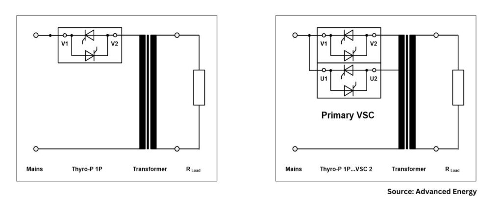
What Are SCR Power Controllers?
Figure 1. SCR power controller
SCR power controllers regulate the power delivered to resistive or inductive loads. Unlike traditional mechanical switches, SCRs offer faster switching times and greater reliability. They are commonly used in applications requiring heating, melting, or bending such as heating elements, motors, and lighting systems.
These devices control electrical power, current, or voltage with high precision and reproducibility. They adjust the phase angle of the AC supply, allowing for finer control over the amount of power sent to the load. This reduces energy consumption and minimizes wear on the equipment, thereby extending its lifespan. Phase-angle firing is designed for high dynamic loads with small thermal inertia and allows for high control dynamic, soft and bump-less loading, and exact current-limit setting.
SCR power controllers produce high manufacturing quality and efficiency through:
Energy efficiency of approximately 99.6%
Power density of approx. 18 W/in3 (for 3-step VSC SCR)
High accuracy up to 1% for output power, 0.5% output voltage
Flexibility
EtherCAT Interface
Traditional SCR operation can be inefficient, especially under partial loads. An energy-efficient mode optimizes the SCR firing angle based on load requirements, reducing energy waste. By adapting to varying loads, these controllers improve system efficiency, lower energy costs, and reduce environmental impact.
Figure 2. Phas-angle firing control mode
Understanding Power Factor
Power factor (PF) is a critical component, representing the ratio of real load power (kW, the actual power consumed) to apparent load power (kVA, the total power supplied). It is a measure of how effectively electrical power is being converted into useful work output. A power factor of 1 (or 100%) indicates maximum efficiency, while lower values indicate wasted energy due to reactive power.
In many industrial settings, a low power factor can lead to higher electricity bills and additional charges from utility companies. Utilities must generate more power to compensate for the inefficiencies caused by reactive power, which does not perform useful work.
Benefits of Improved Power Factor and Reduced Harmonics
One significant advantage of using SCR power controllers is the ability to minimize harmonic distortion. Harmonics are voltage or current waveforms that deviate from the ideal sinusoidal wave, often caused by non-linear loads like electronic devices. These distortions can lead to overheating, equipment damage, and inefficiencies within the electrical system.
Figure 3. Power triangle
Reducing harmonics improves the overall efficiency of power systems and smoother equipment operation, which can prevent costly downtime. Additionally, improving power factor can result in financial savings by reducing energy loss, lowering demand charges, and increasing the capacity of existing electrical infrastructure.
This results in lower energy bills, less wasted energy, and better system reliability. Improved power factor can also help meet regulatory standards requiring specific power factor levels.
Special Energy-Efficient Mode, Voltage Sequence Control (VSC)
VSC complements SCR technology to enhance power system performance by managing voltage levels more effectively. It systematically sequences voltage application to loads, which improves power quality and extends the lifespan of equipment.
VSC is particularly beneficial for applications with inductive loads, where voltage management can significantly reduce inrush currents and mitigate harmonics. By integrating VSC with SCR technology, industries can harness the benefits of both systems, ensuring a stable and efficient power supply.
Combined Advantages of SCRs with Voltage Sequence Control
Improved energy efficiency: By optimizing firing angles and managing voltage sequences, facilities can achieve substantial reductions in energy consumption.
Cost savings: Lower energy usage translates directly into reduced operational costs, making these technologies economically attractive for businesses.
Enhanced equipment longevity: By reducing stress on electrical components through better voltage management, both SCRs and VSC can prolong the operational lifespan of machinery.
Environmental impact: Energy-efficient systems contribute to lower greenhouse gas emissions, aligning with global sustainability goals and regulatory standards.
Figure 4. Comparison phase-angle firing versus VSC
Advantages and Disadvantages of Using SCR in Voltage Sequence Control Mode
Here are several of the advantages:
Improved stability: Helps maintain voltage stability across the system, reducing the risk of voltage fluctuations and outages.
Enhanced performance: Optimizes the performance of electrical equipment by ensuring they operate within their rated voltage range, improving efficiency.
Protection against voltage imbalances: Monitors and adjusts for voltage imbalances in three-phase systems, which can prevent equipment damage and reduce wear.
Energy efficiency: By maintaining optimal voltage levels, VSC can lead to energy savings and lower operational costs.
Automated control: Often incorporates automation, allowing for real-time adjustments without manual intervention, thus improving response times.
Lowest level of harmonics: VSCs can help minimize harmonic distortion in electrical systems.
Lowest level of reactive power: The specific control design of the VSC can significantly impact the minimum achievable reactive power level, even in a weak grid.
Figure 5a. Standard circuit VAR (phase angle) / Figure 5b. VSC circuit
Compare with a few disadvantages:
Large footprint: Larger power controller footprint versus standard SCR power control system.
Initial cost: The initial investment in VSC systems and related technology can be higher, but payback time is less than a year.
Conclusion
Figure 6. Power factor over outpower in VAR (phase angle) blue line vs. VSC red line
In-house heat treat operations aiming for greater efficiency and cost reduction can benefit from VSC, the energy-efficient mode for SCR power controllers. By enhancing power factor and reducing harmonics, these devices optimize energy use and support sustainable, cost-effective operations. Adopting such technologies leads to significant improvements in industrial power consumption and enhanced savings for end users.
About the Author:
Janelle Coponen Senior Product Marketing Program Strategist Advanced Energy
With more than 21 years of experience in the industrial and energy sectors, Janelle Coponen bridges the gap between technical solutions and market needs. At Advanced Energy, she works alongside engineering teams to translate complex technologies into market ready strategies ensuring alignment between engineering innovations and business objectives.
Christian Schaffarra Director of Research and Development Power Control Solutions’ Engineering Team Advanced Energy
With more than 30 years of experience, Christian Schaffarra leads a research team dedicated to developing and advancing innovative power control technologies, ensuring optimal performance and reliability. He has a deep understanding of both the technical and marketing requirements that drive successful product development and engineered solutions.
In this article, a team of researchers describe the technical, technological, and metallurgical characteristics in heating large-sized continuous cast slabs made of low carbon microalloyed steels, using the operation at DanSteel’s rolling complex 4200 as a case study. These characteristics ensure high quality heating process of slabs used for production of high-quality heavy plates weighing up to 63 tonnes*, which are particularly in demand in the offshore wind energy and bridge construction industries.
On the research team are the following: Eugene Goli-Oglu, Sergey Mezinov and Andrei Filatov, all of NLMK DanSteel, and Pietro della Putta and Jimmy Fabro of SMS group S.p.A.
This informative piece was first released inHeat Treat Today’sDecember 2024 Medical & Energy Heat Treat print edition.
*1 metric ton = 2204.6 pounds
The production of structural heavy plate steel is a complex multi-step process, the technological steps and operations of which have an impact on product quality and production economics. Slab reheating for rolling is one of the key process steps in the technological chain, directly linked to the quality and cost efficiency of heavy plate production process.
At DanSteel’s rolling complex 42001, continuously casted (CC) slabs are heated either in pusher type furnaces or walking beam furnaces depending on their cross section. In the case of big-size and heavy tonnage slabs with a cross-section of H x B up to 400 x 2800 mm, heating takes place in the latest generation of the SMS group walking-beam reheating furnace, installed in 2022. The main objectives of the installation of the new reheating furnace were the expansion of the product range towards the production of XXL high-quality heavy plates weighing up to 63 tonnes, which are most in demand in the offshore wind power and bridge construction industries, as well as improving the quality, economic, and environmental parameters of slab reheating process.
Figure 1. Effect of reheating temperature on particle size (a) and austenitic grain size (b) in steels (see reference 5) microalloyed simultaneously with Ti and Nb: 1 — steel with low titanium additions (Ti/N=3.24) 2 — steel with 0.02% Nb and Ti (Ti/N=3.33) 3 — steel with increased titanium content Ti/N=4.55
The aim of this article is to describe the technical, technological, and metallurgical characteristics in heating large-sized continuous cast slabs made of low carbon microalloyed steels and how this looks at the DanSteel’s rolling complex 4200.
Metallurgical Characteristics of Slab Heating
Heating of low carbon microalloyed steel slabs is one of the key technological steps in forming the optimal microstructural condition of heavy plates and their surface quality. In conjunction with microalloying, the technological parameters of heating affect such important characteristics as average grain size and uniformity of the austenitic structure, the composition of the solid solution and the type/thickness of the surface scale. In terms of heavy plate quality, the main realized task at the reheating stage is to obtain at the exit a slab with a setup temperature, the minimum temperature gradient along the thickness, width and length of the slab, optimal quality and quantitative condition of the surface scale.
The heating temperature and its uniformity are important to form a microstructure of increased uniformity. It is known2 that a fine-grained austenitic steel structure has an increased grain boundary surface per volume unit, which leads to an excess of free energy of the system, which creates a driving force that determines the subsequent grain growth. The austenitic grain grows exponentially when heated in certain temperature ranges and this grain growth tendency is always present in low carbon microalloyed steels.
Figure 2. Growth pattern of austenitic grains in steels containing various microalloying elements
There are two general mechanisms of austenitic grain growth when heating slabs: normal and abnormal growth. That is, when reaching a certain temperature, which depends on the chemical composition, the austenite grain begins to increase very rapidly in apparent diameter. Abnormal grain growth can be observed in austenitizing steels containing strong CN-forming elements. Anomalous grain growth is not observed in simple low alloyed Si-Mn steels but at heating temperatures of 2102°F–2192°F, the grain grows to very large sizes (200 μm and larger).3
To avoid exponential grain growth of austenite during heating for rolling, dispersed particles that inhibit grain boundary migration are effectively used.4 The undissolved particles inhibit the migration of grain boundaries and thus inhibit the growth of austenitic grains. The nature of the release of particles and their effect on the average size of the austenitic grains of Ti and Nb alloyed low carbon steels is shown in Figure 1. It is important that the slab at the exit of the furnace has a given heating temperature without gradient limit deviations.
The main microalloying elements that form the optimal (fine grain) austenite structure as a result of the solid-solution effect and the formation of nitrides and carbides during slab heating are titanium, niobium, and vanadium (Figure 2).5 Titanium forms nitrides, which are stable at high temperatures in the austenitic range and allow control of the austenite grain size during heating before hot deformation. The binding of free nitrogen (which has a high affinity for carbide forming elements) by titanium has a positive effect on steel ductility and makes niobium more effective. Niobium is an effective microalloying element for refining the austenite grain during heating for rolling.6 It also has the positive effect of inhibiting austenite recrystallization during thermomechanical rolling.7
It is worth noting a number of works8, 9, 10, in which it was shown that increasing the heating temperature of V-Ti-Nb steel and the associated austenite grain enlargement does not significantly affect the size of the recrystallized grain, formed in the temperature range of complete recrystallization after repeated deformation under the same temperature and deformation conditions. This experimental result at first sight contradicts most recrystallization models11, 12, according to which the size of recrystallized austenite grain depends on the initial (before deformation) grain size and deformation temperature.
The microstructure and mechanical properties of the finished product directly depend on the heating temperature and are determined by the size and homogeneity of the austenitic grains, the stability of the austenite itself, influencing the condition of the excess phase and, consequently, the kinetics of its subsequent transformation. For timely recrystallization processes and control of dispersion hardening, it is necessary to balance the uniform fine grained austenitic microstructure and the transition of dissolved particles into solid solution when defining the heating temperature. Also, the heating temperature must be sufficiently high to fully undergo recrystallization in the interdeformation pauses.13 It should also be considered the possible negative phenomena of local and general overheating that occur when heating a slab above a certain temperature for a given steel and lead to a sharp increase in the austenitic grain size. The decreased heating temperature allows for a number of technological advantages: The possibility of reducing the pause time for cooling before the finishing step of rolling, increasing productivity of furnaces due to reduced heating time for rolling, and therefore the mill as a whole, as well as reducing the cost of the product due to saving fuel and reducing losses on scale. However, it should be remembered that some groups of low carbon steels have an optimal temperature range for heating, target temperatures above or below, which increase the heterogeneity of the microstructure. Thus, ensuring uniform heating to a given holding temperature and discharging slabs from the reheating furnace for subsequent rolling is an important technological task and contributes to the formation of austenitic microstructure and solid solution state of low carbon microalloyed steel with increased uniformity.
DanSteel Walking Beam Reheating Furnace
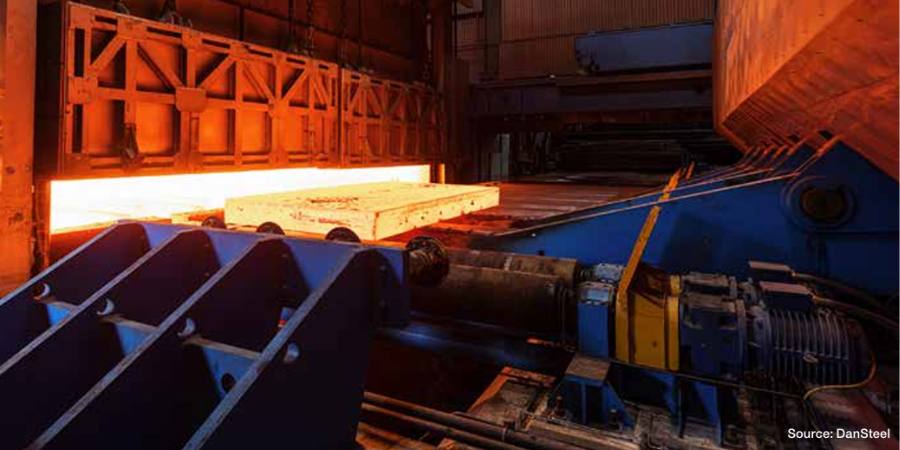
In 2022, DanSteel and SMS commissioned a new walking-beam reheating furnace (Figure 3) with a design capacity of up to 100 tonnes/hour, expanding the range of slabs heated to a maximum cross section of H × B 400 × 2800 mm and improving heating quality. The maximum temperature difference between the coldest and the hottest points on the slabs is not more than 30°C. The new furnace has been designed with a focus on environmental and energy efficiency and has reduced CO2 emissions by 17–18% compared to the furnaces already in operation in the plant.
Figure 3. DanSteel walking beam reheating furnace no. 3, (left) general view of the furnace and (right) slab discharging area
The walking beam reheating furnace is for heating cast carbon, low-carbon, and low-alloy steel slabs weighing up to 63 tonnes. The main production characteristics of the furnace as part of DanSteel 4200 rolling complex are shown in Table 1.
Slabs are moved through the furnace by moving the walking beam in four steps: lifting, moving forward, lowering below the level of the fixed beams, and moving the walking beams backwards. The speed of the slab moving in the furnace is controlled by changing the movement intervals between the movement cycles of the beams and depends on the variety of heated slabs. Slab discharging from the furnace is carried out shock-free, using a special machine that moves the slabs from the furnace beams to the mill roller conveyor. The furnace is equipped with a modern automated process control system and a system of instrumentation and sensors that allows the heating of steel without the direct involvement of technical personnel and provides for the measurement, regulation, control, and recording of all operating parameters.
The furnace type is reheating, walking beam, regenerative, multi-zone, double-row, double-sided heating, frontal charging, and discharging furnace. The furnace is designed for natural gas operation with the possibility of a quick conversion, within three weeks, of up to 40% of the capacity for hydrogen operation. The conversion is carried out by means of a minor modernization of the burner’s inner circuit, the installation of hydrogen storage auxiliary equipment and the regulation of the hydrogen supply to the modified nozzles. It is planned that the replacement of natural gas by hydrogen will also reduce the consumption of natural gas by ~40% and hence reduce the negative impact of the process on the environment. Feeding control as well as optimum pressure is controlled by a special automated control system. Table 2 shows the main technical characteristics of the furnace.
The air is heated in a metal recuperator, located on the furnace roof. The combustion products pass between the tube and the air passes through the recuperator tubes. The air is blown by a blower into the recuperator and transported to the burners through thermally insulated air ducts. The gas and air from the common pipelines are supplied to each zone via zone headers, on which flow meters and actuators for flow controllers are installed to ensure an ideal furnace atmosphere with an O2 content of about 0.7–1.0 %.
The furnace has 6 heating zones, 3 upper and 3 lower, with 24 SMS-ZeroFlameTM burners (Figure 4a) for ultra-low nitrogen oxide concentrations and high thermal efficiency.14 The burners consist of a metal casing with external cladding for heat protection, several fuel and combustion air lines, a pre-combustion chamber and an air deflector made of refractory material with high alumina content.
Figure 4. SMS-ZeroFlameTM burners used in DanSteel’s walking beam furnace: a – burner structure; b – flame operation; c – flameless (“invisible flame”) operation
The particular design of the installed burners allows them to operate using three modes:
Flame mode (Figure 4b), used for ignition and at low temperature, but even then, the NOx level remains low thanks to the triple-stage air supply
Flameless mode (“aka invisible flame,” Figure 4c), which ensures high slab heating uniformity over the cross section creating a homogeneous, invisible flame with minimum NOx emissions
Mixed “booster” mode, allowing a 15% to 20% increase in nominal heat input, and a rapid increase in zone temperature if the furnace setting is changed due to a change in steel grade or increased capacity
Figure 5. Heating curves of a 250 x 2800 mm slab in the new reheating furnace no. 3
The combustion gases from the gas combustion heat the metal through direct radiant heat transfer, as do the combustion gases heat the burner units, the furnace roof and walls, which in turn heat the slabs in the furnace through indirect radiant heat transfer. The optimum combination of burner arrangements ensures intensive and uniform heating. The mutual movement of combustion gases and metal is counter current. Combustion gases from the recuperation zone are conveyed by a waste gas duct to the heat exchanger (where they heat the air) and then through a waste gas intake to the chimney and exhausted to the atmosphere. The rotating valve is installed in the exhaust duct between the recuperator and the chimney and is used to control the pressure in the heater.
Figure 6. Heating curves of a 400 x 2800 mm slab in the new reheating furnace no. 3
The skids are cooled by chemically treated water, which circulates in a closed circuit. A dry fan cooling tower is used to dissipate the heat from the cooling water. Steel is charged into the furnace by a charging machine that moves the slabs from the charging roller table to the furnace skids.
Technical Features of Slab Heating
The highly even heating of slabs in furnace 3 of DanSteel is ensured by the optimum arrangement of the burners, flameless fuel combustion, triple skids shift, and warm riders on the skids. The evenness of the slab heating corresponds to a maximum temperature difference in the longitudinal section of up to 20°C, and the maximum difference between the coldest and hottest points of the slab must not exceed 30°C.
Earlier in work15, it was shown that when heating a 250 mm slab in the old furnace no. 2, the maximum temperature gradient was for a long time within 250-300°C, and at the exit of the furnace the slab had a sensitive temperature difference in cross section. Figure 5 shows an industrial schedule of heating slabs cross-section 250 x 2800 mm in the new furnace no. 3. Analyzing thermal and technical data of slab heating for heavy plate production using the new furnace, it should be noted that the slab temperature uniformity distribution during the whole heating period is essential. When heating slab cross-sections 250 x 2800 mm in the new furnace, the maximum temperature gradient does not exceed 130°C (Figure 5). The peak values of temperature gradients are situational in nature and appear only for a short period of time and at times of adaptation of the control model of heating for each specific slab in the active zones of the furnace. For slabs with a thickness of 250 mm the most critical time is the time interval between approx. 90 and 120 minutes during which the upper and lower surfaces of the slab are actively heated. During the last 20 minutes in the soaking and equalizing phase, the temperatures at ¼, ½, and ¾ of the slab thickness reach a maximum gradient of no more than 20°C. As can be seen from the graph in Figure 5, heating of 250 x 2800 mm slabs to a given temperature of 1150°C takes no more than 4.5 hours. It is possible to reduce the heating time, however, with a certain decreasing of quality.
Figure 7a-b. Temperature gradients of 120 mm heavy plate, produced using TM+ACC modes: a, b — top surface thermoscanner data
A similar schedule for heating 400 x 2800 mm slabs is shown at Figure 6. For large cross-section slabs with a thickness of 400 mm, the heating time is in the range of 9–10 hours. The heating time can be reduced to 8 hours, but also with a decrease in the quality of heating towards an increase in the temperature gradient across the thickness of the slab. It should be noted that the temperature increases smoothly in the heating curves at ¼, ½, and ¾ of the slab thickness. From the peaks of the upper furnace temperature curve, the discreteness of the adaptation adjustments of the furnace heating control model can be evaluated.
Heavy Plate Temperature Profile
The DanSteel 4200 Rolling Complex is equipped with twelve control pyrometers and three thermo scanners that measure the temperature of 100% of the top surface of the plate at reference points in the heavy plate production process. The data obtained can be used to accurately and in real time evaluate the temperature uniformity of the plate in width and length direction.
Figure 7 c-f. Temperature gradients of 120 mm heavy plate, produced using TM+ACC modes: c, d (top) — temperature profile of top surface from pyrometer; e, f (bottom) — temperature profile of bottom surface of plate from pyrometer
As an example, Figure 7 shows the results of a scan of the surface temperature of 120 mm thick rolled steel heavy plate after deformation stage is completed and before the start of final cooling in an accelerated cooling unit. Two states of temperature gradients occurring during production are considered: uneven heating and uniform heating. Figure 7a shows the temperature field of a plate with expressed temperature irregularity. The main reason for the marked irregularity in the temperature field of the rolled plate is non-optimal modes of heating of the slab. It can be seen that the central part of the plate has the temperature specified by the technology, while the head and tail overheated by 50-60° C relative to the specified temperature at a maximum permissible deviation of not more than 30°C. Figure 7b shows the temperature field of a plate with a high degree of uniformity. Approximately 95% of the surface of such a plate is at the process-specified temperature with a deviation of ±3°C. The maximum temperature gradient does not exceed 10°C.
The temperature profiles of the top (Figure 7c and Figure 7d) and bottom (Figure 7d and Figure 7e) rolled surfaces, obtained from control pyrometers, show that the nature of the temperature non uniformity is repeated on the upper and lower surfaces of the plate. In the first “non-optimal” case the temperature gradient of the top surface reaches about 76°C, and on the bottom surface: -54°C. In the case of uniform heating, the gradient of the top surface of the plate does not exceed 3–6°C and the bottom surface: 5–11°C.
Preventive Maintenance System
The DanSteel new walking beam furnace is also equipped with an innovative maintenance support tool named SMS Prometheus PMS (Preventive Maintenance System). It consists of a software platform collecting and elaborating the data provided by an extended number of sensors strategically placed over several mechanical components of the furnace, with the goal of predicting possible malfunctioning. The monitored equipment includes the key handling devices, like the slab charger, the slab extractor or the walking beam system, as well as the hot air recuperator, the combustion air fans of the main components of the water treatment fan. The software algorithm is able to extrapolate some data from the sensor measurements to assess the key performance trends of the related component and anticipate the necessity of intervention for maintenance or repair before any actual damage happens.
Figure 8. Dashboard handling — monitoring of the walking beam system
In the example of Figure 8, the trends are shown that correlate the walking beam movement and the cylinders pressure to the slab load inside the furnace. Any significant deviation in respect to the foreseen pattern denotes a movement anomaly and will trigger a notification to the control system, that allows the plant maintenance team to act preventively in view of a potential failure.
Conclusion
A new walking-beam reheating furnace with a designed productivity of up to 100 t/h was put into operation at DanSteel rolling complex 4200. This allowed expanding the range of heated large-size slabs with a maximum cross-section of H x B 400 x 2800 mm and weighing up to 63 tonnes. The implemented project has provided increased uniformity of heating along the thickness, width and length of slabs with average maximum values of temperature gradients in the three directions not exceeding 30°С (80°F) and reduced consumption of natural gas to the level of 31–32 m3/t of finished product. More uniform heating of slabs ensured improved temperature field uniformity of rolled heavy plates. The constructive possibility of a partial transition to the use of hydrogen instead of natural gas was taken into account.
References
I. Sarkits, Y. Bokachev, E. Goli-Oglu, “Production of heavy plates on the rolling mill 4200 DanSteel A/S,” Stahl und Eisen. 2014. no. 4, 57–61.
Imao Tamura, Hiroshi Sekine, Tomo Tanaka, Chiaki Ouchi, Thermomechanical Processing of High-strength Low-alloy Steels (Butterworth-Heinemann, 2013), 256.
Antonio Augusto Gorni and José Herbert Dolabela da Silveira, “Accelerated Cooling of Steel Plates: The Time Has Come,” Journal of ASTM International 5, no. 8 (2008): 358–365.
Y. I. Matrosov, “Complex microalloying of low-pearlite steels subjected to controlled rolling,” Met Sci Heat Treat No. 28 (1986): 173–180.
S. V. Subramanian,, G. Zhu, C. Klinkenberg, K. Hulka, “Ultra Fine Grain Size by Dynamic Recrystallization in Strip Rolling of Nb Microalloyed Steel,” In Materials Science Forum. Vols. 475–479 (2005): 141–144.
S.C. Hong, S. H. Lim, “Inhibition of Abnormal Grain Growth during Isothermal Holding after Heavy Deformation in Nb Steel,” ISIJ International 42, no. 12 (2002): 1461–1467.
K. Hulka, A. Kern, U. Schriever, “Application of Niobium in Quenched and Tempered High-Strength Steels,” Materials Science Forum vols. 500–501 (2005): 519-526.
C. M. Sellars, J. A. Whiteman, “Recrystallization and Grain Growth in Hot Rolling,” Metal Science no. 13 (1979): 87–194.
H. Tamehiro, N. Yamada, H. Matsuda, “Effect of the Thermo-Mechanical Control Process on the Properties of High-strength Low Alloy Steel,” Transactions of the Iron and Steel Institute of Japan Vol. 25, Issue 1 (1985): 54–61.
Sh. Liang, F. Fazeli, H. S. Zurob, “Effects of solutes and temperature on high-temperature deformation and subsequent recovery in hot-rolled low alloy steels,” Materials Science and Engineering A., vol. 765 (2019): 138324.
H. Yada, “Prediction of Microstructural Changes and Mechanical Properties in Hot Strip Rolling,” Proceeding of the International Symposium on Accelerated Cooling of Rolled Steel. Winnipeg, Canada. 1988. 105-119.
W. Roberts, A. Sandberg, T. Siweski, T. Werlefors, “Prediction of Microstructure Development during Recrystallization Hot Rolling on Ti-V-steels,” ASM HSLA Steels Technology and Applications Conference. Philadelphia, USA. 1983. 35–52.
R. Wang, C. I. Garcia, M. Hua, K. Cho, H. Zhang, A. J. Deardo, “Microstructure and precipitation behavior of Nb, Ti complex microalloyed steel produced by compact strip processing,” ISIJ international 46, no. 9 (2006): 1345-1353.
“Innovation in combustion process,” SMS group, https://www.sms-group.com/en-gb/insights/all-insights/innovation in-combustion-process (date of review 2023-03-20).
V. A. Tretyakov, Bokachev, A. Yu, A. N. Filatov, E. A. Goli-Oglu, Development of a digital twin of the process of controlled rolling of thick plate from high-strength low-alloy steels. Message 1. Simulation of slab reheating in continuous furnace with a prediction of austenite grain size before rolling. // Problems of ferrous metallurgy and materials science. 2022. no. 2, P. 30-40.
This article content is used with permission by Heat Treat Today’smedia partner Furnaces International, which published this article in September 2023.
About the Authors:
Eugene Goli-Oglu Head of Product Development, Technology and Technical Sales Support NLMK DanSteel Andrei Filatov Metallurgist Product Development and Technical Sales Support NLMK DanSteelPietro della Putta Vice-President Reheating and Heat Treatment Plants SMS group S.p.A.Jimmy Fabro Head of the Technical Department – Furnace Division SMS group S.p.A.
Eugene Goli-Oglu has worked at NLMK DanSteel since 2013 and has led Product Development, Technology and Technical Sales Support functions for steel heavy plate production. Eugene received his Master degree in Metal Forming in 2007, a second Master’s degree in Economy in 2009, and a PhD in Metallurgy and Thermal Processing of Metals and Alloys in 2012. He has authored/co-authored 90+ publications in technical journals.
Sergey Mezinov has worked at NLMK DanSteel since 2007 as an engineer of the Project Department and process engineer of the Quality Department. In 1995, Sergey graduated as an heat-power engineer. He has authored/co-authored of 2+ publications in technical journals and authored/co-authored two patents.
Andrei Filatov has worked at NLMK DanSteel since 2019 as a metallurgist in the Product Development and Technical Sales Support department. In 2015, Andrei graduated as an engineer physicist, and in 2019, he completed postgraduate studies in Metallurgy and Thermal Processing of Metals and Alloys. He has authored/co-authored 20+ publications in technical journals.
Pietro della Putta is the vice president of the Reheating and Heat Treatment Plants department at SMS group S.p.A. Jimmy Fabro is the head of the Technical Department – Furnace Division at SMS group S.p.A.
Jimmy Fabro is the head of the Technical Department – Furnace Division at SMS group S.p.A.
If you work in a standards-driven industry, you may already feel the imperative of digitalization. In today’s Technical Tuesday, Mike Loepke, head of Nitrex Software & Digitalization, posits how, even if you aren’t necessitated to track compliance digitally, you are probably looking to synthesize and leverage the strengths of multiple advanced operations — furnace and process record-keeping, knowledge of furnace past operations, juggling different new equipment capabilities — across just one platform. In other words, you are looking to bring digitalization system management to your operations.
This informative piece was first released inHeat Treat Today’sDecember 2024 Medical & Energy Heat Treat print edition.
The Future of Heat Treatment Relies on Digitalization
The ultimate goal for heat treaters, whether commercial or captive, is to uphold the quality of their product and meet client expectations while remaining profitable. Digitalization supports these efforts as it synthesizes and presents detailed, transparent, and accessible data that allows heat treaters to better manage their equipment, processes, and product quality. In addition, the collection of detailed information can serve as a database of knowledge to be used by the next generation of heat treaters, supporting future viability and advancement in the field.
There are necessary steps to take to establish a digital solution and essential components to look for when choosing a software platform that assists heat treaters in optimizing equipment and processes, effectively creating the digitalization of the heat treat operations. Let’s explore these now.
How Digitalization Optimizes Heat Treatment Processes
Digitalization in the heat treatment industry relies on the integration of industrial internet of things (IIoT) technologies with traditional and modern heat treatment processes. Using enabling devices such as sensors, modern connectivity methods, analytics, machine learning, and IIoT software platforms, it is possible for heat treaters to collect and process data that, after analysis, drives informed decisions to optimize equipment, processes, and product quality. To put a finer point on it, digitalization occurs when a manufacturing system is digitally integrated to capture and preserve human experience and knowledge, forming a holistic virtual representation of heat treat operations.
Figure 1. QMULUS Shop Layout enables visual inspection of the current production status, the
location of goods and parts, as well as the real-time status of assets and their ongoing processes. Source: Nitrex
While digitalization varies from industry to industry and plant to plant, there are some common ways in which heat treaters can employ digital technologies to build such a system. Firstly, digitally integrated solutions can optimize process management and control. For example, when a sensor detects a temperature anomaly during a heat treatment process, the integrated software platform picks up that reading, analyzes it in real time, recognizes it as an error based on historical data or programmed parameters, and alerts the operator.
This integration also facilitates predictive, condition-based maintenance. For example, if collected data and analysis suggests that a furnace is behaving abnormally, the system can automatically generate a work order along with a list of potential failure causes, so that a technician can troubleshoot, identify, and correct small issues — such as a failing thermocouple — before they impact quality or result in equipment failure. By addressing these proactively, heat treaters can avoid extended periods of costly unplanned downtime and ensure continuous operation.
Secondly, artificial intelligence through machine learning plays a crucial role in optimizing quality control in a digitalized system. By analyzing data collected during heat treating processes, it learns to detect patterns and identify anomalies. As in the examples above, this capability enables the system to identify deviations from the desired outcomes, allowing heat treaters to quickly rectify any issues before they impact quality.
Figure 2. The heart of the IIoT data platform needs to be thoughtfully planned and designed. Illustrated are 5
steps to follow to ensure the cloud data system properly engages with the data generated from your specific
heat treat operations, ultimately delivering actionable insights. Step 1 depicts the various data sources;
Step 2 shows the data transformation, integration, and processing stages; Step 3 highlights the central
QMULUS database where data is indexed and organized; and Steps 4 and 5 demonstrate how data is further
processed, distributed, and accessed by different end-users. Source: Nitrex
Thirdly, algorithms can be programmed into a comprehensive management system to identify the most energy-efficient operating conditions for the heat treating process, helping heat treaters reduce their carbon footprint, minimize energy costs, and comply with sustainability goals.
In addition to these types of operational advantages, digitalization technologies can also be used to create a database of knowledge before experienced operators and experts leave the workforce. Traditionally, a handful of experts in the plant oversee the furnaces and equipment and understand how to best control and maintain them based on experience. However, passing down this knowledge to the next generation of heat treaters can take years, which may not be possible due to a company’s workflow demands and cost pressures. Digitalization addresses this challenge by creating a streamlined and accessible database of knowledge, offering less experienced operators and technicians immediate access to detailed information about what may be happening in the equipment or process for an issue at hand. This ensures that essential insights are not lost and enables quicker problem-solving and decision-making on the shop floor.
Making the Digitalization Transformation
While digitalization presents obvious advantages, the heat treatment industry, often conservative in its approach to technology, has some initial work and investment required before realizing the full benefits.
Going “paperless” in order to unlock the full potential of the available data is an important first step. All reports, histories, drawings, and other paperwork associated with equipment, processes, maintenance activities, product quality, and other relevant information should be digitized to provide a comprehensive view of both historical and current data.
Connectivity and integration between machine and higher-level systems are essential for effective data acquisition, monitoring, and remote control. SCADA systems, Manufacturing Execution Systems (MES), and other higher-level systems are rich sources of machine and process data. Gathering and analyzing this data can provide actionable insights that operators can use to make smarter decisions about the control and maintenance of equipment and processes.
Figure 3. A comprehensive overview displays all detected control loop anomalies, indicating possible root causes as well as recommended actions. Incorporating feedback from the responsible maintenance personnel further improves accuracy and delivers more effective recommendations for future
occurrences. Source: Nitrex
Finally, just having data is not enough. The data must be accessible, transparent, and relevant to be valuable. Achieving a complete picture of all the collected data, known as data consolidation, is necessary.
To build an IIoT platform with a well-architectured data engine, heat treaters should begin by identifying and understanding the different sources of data provided by sensors and high-level systems. This involves integrating the data through interfaces adapted to the data type and source, as well as documenting the integrated data sources, data fields, and data streams. Next, a “data lake” should be created to store the collected raw data. From this foundation, a data warehouse can be established to store enriched or analyzed data, derived values, data models, and forecasts in an organized way. For heat treaters, this type of contextualized data might be grouped by parts, loads, or orders.
Once the data engine is in place, the information stored in the data warehouse must be presented in a way that makes sense to operators and technicians for them to make informed decisions for heat treatment processes. To facilitate this, a universal data interface should be considered.
Building from this well-architectured data engine, the IIoT platform can then be expanded with statistical analytics, remote monitoring, KPI tracking, machine learning, artificial intelligence, and other applications to optimize processes and increase profitability.
What Heat Treaters Need in a Digitalization Solution
Harnessing modern technologies tomake digitalization a reality presents heat treaters with the opportunity to implement a solution based on a complete and well documented data system. It also means that the solution creates a holistic solution to data analysis, interpretation, reporting, and action that supports the real-world actions of heat treaters on the plant floor and in the office.
For this reason, a digitalization solution that has cloud and on-premises allows real-time access to analysis and alert messages for operators on the floor as well as managers who are away from the plant, ensuring quick problem-solving and maximum uptime in the event of process or machine issues.
Additionally, heat treaters should look for a solution that offers the freedom to integrate all the various platforms and equipment from which data are gathered from. These may include relevant machinery and production data from the shop floor as well as third-party and custom controllers. This flexibility to synthesize information from multiple sources will ensure the digitalization efforts lead to a comprehensive solution with actionable process overviews, recipe control, batch tracking, and other customization options.
To further this intent of a holistic solution, heat treaters should consider various data capabilities with different portal views, such as a manufacturer portal, a plant portal, and a client portal. However, considering the historic value of a comprehensive software solution, it may be worthwhile to consider how each user could transfer direct feedback and add new rules into the system, creating a repository of knowledge that bridges the knowledge of outgoing generations to future heat treaters.
Finally, any platform that directs the digitalization of a plant must prioritize robust security measures. Several features to look for are:
enhanced encryption standards to keep data confidential and tamper-proof during transmission and storage;
secure protocols based on industry best practices to safeguard data integrity;
a granular access control system (ACS) to allow IT administrators to define and manage user permissions of authorized personnel, thereby minimizing the risk of data breaches and unauthorized data manipulation; and
intrusion detection and prevention systems to continuously monitor network and system activities, enabling instant identification and mitigation of suspicious behavior. This serves as an additional layer of defense against potential cyber threats.
Beyond the software setup, be sure to use best practices by conducting regular security audits to assess the platform’s vulnerabilities and ensure compliance with evolving cybersecurity standards. While digitalization of heat treat operations may seem like a task for the next generation to complete, secure software options that integrate the hard work of digitizing plant activities can make this endeavor just a step away.
About the Author:
Mike Loepke Head of Nitrex Software & Digitalization Nitrex
Drawing from a background in Mathematics and Physics, coupled with extensive R&D experience and metallurgical modeling, Mike Loepke specializes in AI and process prediction. He has led Nitrex’s initiative in developing QMULUS, a pioneering IIoT cloud-based platform. Mike’s relentless pursuit of knowledge keeps him at the forefront of evolving technology.
The Heat Treat Doctor® has returned to offer sage advice to Heat Treat Today readers and to answer your questions about heat treating, brazing, sintering, and other types of thermal treatments as well as questions on metallurgy, equipment, and process-related issues.
Contact us with your Reader Feedback!
Clients often want to know or specify that their component part surfaces are “bright” or “shiny” or “clean.” Other times they desire to have a surface condition that is “scale free” or “oxide free” after heat treatment. But how, if at all, can we quantify what these terms mean? Let’s learn more.
“Shiny” and “bright” are words that are highly subjective. This is often a source of confusion not only for the heat treater, but the manufacturer and, in some cases, even the end user of the products. Heretofore, the answer depended on one human being’s interpretation as opposed to another, and evaluations depend not only on the type of material but also the mill practices used, manufacturing methods employed, heat treatment processes, and the level and type of contamination introduced before and after processing.
Traditional Approach
Figure 1. Temper color chart atmosphere or tempering in air or an “inert” gas such as nitrogen. Source: Abbott Furnace Company
Traditionally, we have relied on color charts (Figure 1) to tell the approximate temperature at which discoloration took place, that is, an oxide formed on the (steel, stainless steel, or tool steel) surface of a component part. This method is still in use today when cooling parts in a furnace
As mentioned, the perception and interpretation of color is different for different people. Lighting (natural light or plant illumination), the environment in which one views color, eye fatigue, the age of the observer, and a host of other factors influences color perception. But even without such physical considerations, each of us interprets color based on personal perception. Each person also verbally describes an object’s color differently. As a result, objectively communicating a particular color to another person without using some type of standard is difficult.
There also must be a way to compare one color to the next with accuracy.
New Approach
Today, portable spectrophotometers (Figure 2) are available to measure color and help quantify brightness measurements. These types of devices are designed to meet various industry standards including:
In simplest terms, a spectrophotometer is a color measurement device used to capture and evaluate color. Every object has its own reflectance, or the amount of light it reflects, and transmittance, or the amount of light it absorbs. A reflectance spectrophotometer shines a beam of light and measures the amount of light reflected from different wavelengths of the visible spectrum, while a transmission spectrophotometer measures how much light passes through the sample. Spectrophotometers can measure and provide quantitative analysis for just about anything, including solids, liquids, plastics, paper, metal, fabric, and even painted samples to verify color and consistency.
Spectrophotometers provide the solution to the subjective problem of interpreting the color of the surface of a component part that has been heat treated, brazed, or sintered because they explicitly identify the colors being measured; that is, the instrument differentiates one color from another and assigns each a numeric value.
As an example, the brightness of steel tubes annealed in a rich Exothermic gas atmosphere was measured against tubes that had not been processed (Figure 3). Having this definite measurement of the surface changes allowed the heat treater to provide their client with a definitive statement on the change after processing.
CIE Color Systems
The Commission Internationale de l’Eclairage (CIE) is an organization responsible for international recommendations for photometry and colorimetry. The CIE standardized color order systems include specifying the light source (illumination), the observer, and the methodology used to derive values for describing color, regardless of industry or use case.
Though spectrophotometers are the most common, for some applications colorimeters can also be used, but these are in general less accurate and less suitable for a heat treat environment.
There are three primary types of spectrophotometers on the market today used for print, packaging, and industrial applications: traditional 0°/45° (or 45°/0°) spectrophotometers, primarily used for the print industry; sphere (or diffuse/8°) spectrophotometers, primarily used in the packaging industry; and multi-angle (MA) spectrophotometers, for use in industrial environments. These instruments capture color information, and in some cases can capture appearance data (e.g., gloss).
Multi-angle (MA) spectrophotometers are best suited for measurements involving special surface effects, such as those found on metal surfaces and coatings and include those with surface contaminants and even can quantify cosmetic appearance. These are typically used on the shop floor, in the lab and in quality control, and even can be found in shipping areas.
MA spectrophotometers require users to verify five or more sets of L*a*b values or delta these terms). They typically have an aperture size of 12 mm, which is too large for measuring the fine detail that occurs in many small-scale industrial applications. Primary illumination is provided at a 45° angle. Some models have secondary illumination at a 15° angle.
Figure 3. Example of a product test — color and oxidation level test. Source: X-RIte
An application example for an MA spec trophotometer lies in their use for collecting colorimetric data on special effects coatings in the automotive industry, capturing reliable color data in cases where special effect coatings are used.
Final Thoughts
In this writer’s opinion, a spectrophotometer should be in every heat treat shop! You will be doing both yourself and your customers a valuable service and take the guesswork out of one of the most commonly asked questions – is it bright?
References
Herring, Dan H. Atmosphere Heat Treatment Volume 1. BNP Media, 2014.
X-Rite Pantone. “A Guide to Understanding Color.” Accessed October 10, 2024. https://www.xrite.com/learning-color-education/whitepapers/a-guide-to-understanding-color.
X-Rite Panatone. “Tolerancing Part 3: Color Space vs. Color Tolerance.” Accessed October 10, 2024. https://www.xrite.com/blog/tolerancingpart-3.
X-Rite Pantone. “X-Rite Portable Multi Angle Spectrophotometers.” Accessed October 10, 2024. https://www.xrite.com/categories/portable-pectrophotometers/ma-family.
About the Author
Dan Herring “The Heat Treat Doctor” The HERRING GROUP, Inc.
Dan Herring has been in the industry for over 50 years and has gained vast experience in fields that include materials science, engineering, metallurgy, new product research, and many other areas. He is the author of six books and over 700 technical articles.
Adapting to new processing demands puts traditional equipment to the test. Can single-chamber solutions keep up, or will applications require different equipment options for efficient processing? In today’s Technical Tuesday, Bryan Stern, product development manager at Gasbarre Thermal Processing Systems, addresses the advantages multi-chamber isolated heat vacuum furnaces bring to the floor.
This informative piece was first released inHeat Treat Today’sNovember 2024 Vacuum print edition.
Do You Hear That? It’s the Sound of Change . . .
In the evolving landscape of vacuum heat treatment, single-chamber batch furnaces have long been the cornerstone of material processing. However, with more traditional processes shifting to vacuum, rising energy costs, and increasing environmental pressure, the disadvantages of that approach are emphasized, enhancing the appeal of alternative technologies. Multi-chamber vacuum equipment, while not new to the industry, offers significant solutions to inefficiencies and challenges faced by single-chamber systems. With advances in technology, improved operational planning, and an increasingly competitive market, multi-chamber isolated heat furnaces are becoming a more viable choice.
What Is an Isolated Heat Vacuum Furnace?
An isolated heat vacuum furnace keeps the heat chamber separate from the ambient atmosphere throughout the process, including loading and unloading. This allows the heated zone to maintain a stable temperature and vacuum between cycles, unlike single-chamber furnaces, which must heat up and cool down for each new load. Key components of this furnace type include an additional evacuation chamber, a dynamic sealing door, and a mechanism for moving the workload between chambers. While multi-chamber isolated heat furnaces may be batch or continuous, the above features fundamentally distinguish them from single-chamber batch equipment. This difference is more than just a technical nuance; it has profound implications for operations and efficiency.
The widespread use of single-chamber vacuum furnaces has significantly shaped the design and operation of vacuum furnaces today. But it is important to remember some of the challenges to this approach that we often take for granted.
Energy Efficiency Has Entered the Chat
Single-Chamber Challenge
In single-chamber systems, the entire furnace must go through a full cycle of loading, evacuation, ramping, soaking, cooling, and unloading for every batch of parts. This adds significant “dead time” on either side of the thermal process. In addition to pump-down time, ramping from room temperature typically adds 1–2 hours to the cycle time before soaking which creates a barrier to throughput. Another drawback is that the energy required to heat the furnace is thrown away after every cycle. Due to the high thermal capacity of materials like graphite and molybdenum, this is not inconsequential. With 100% thermal efficiency defined as only consuming the energy required to heat the work and fixturing, single-chamber batch furnaces typically operate in a thermal efficiency range of around 30%–50%.
Isolated Heat Advantage
In an isolated heat furnace, the work zone remains at temperature and the energy required to heat the furnace is not thrown away. Additionally, the introduction of work to a preheated work zone allows the load to be heated more quickly, reducing the time required to achieve temperature and reducing holding losses. While multi-chamber batch furnaces experience some savings, they still consume excess energy since the heat cage is empty during unloading, loading, and evacuation. Continuous configurations, however, see significant improvement with only holding losses and the energy required to heat the work and fixturing being consumed. These advantages mean that continuous furnaces typically operate in a thermal efficiency range of 45%–65%. The result is a 15%–35% energy efficiency improvement over the majority of existing equipment.
The tension of designing a single-chamber furnace to handle both heating and cooling in the same space presents substantial challenges. Insulation pack thickness is often limited to balance the need for quick pump-down. Gas nozzle penetrations through the insulation pack create direct radiation losses. This erodes thermal efficiency, adds thermal mass, and restricts gas flow during cooling. These conflicting design priorities often lead to unsatisfactory compromises and fluctuating designs. Between the additional energy to heat and cool and increase power demand at temperature, there are a lot of energy savings being left on the table.
Isolated Heat Advantage
Because the heating and cooling take place in separate locations, multi-chamber isolated heat equipment benefits from the ability to have dedicated designs tailored at each work position. More insulation can be used as conditioning time is not a significant consideration. Additionally, the insulation can be designed without penetrations, further reducing losses. Moving the work to a dedicated cooling position removes restrictions to gas flow and allows the work to radiate directly to the cold wall. This is especially beneficial at the beginning of a quench when the work is at high temperature. This can allow cooling rates to be achieved with lower quench pressures and smaller quench motors.
Thermal Cycling: Here We Go Again . . .
Single-Chamber Challenge
A single-chamber furnace must be built to endure extreme thermal cycling again . . . and again. This requires detailed design consideration to account for thermal shock, expansion, ratcheting, creep, and low-grade oxidation — all of which contribute to maintenance and replacement cost for expensive, long lead refractory components.
Isolated Heat Advantage
Since the heated portion of the furnace remains at stable temperature and vacuum, internal components are not subject to the same destructive forces. An isolated heat cage can remain in service much longer before requiring service or replacement. It also decreases the likelihood of sudden and unexpected equipment failure. Increasing the lifespan of the most expensive consumable assembly in the furnace is an incredibly valuable advantage that is frequently overlooked.
Find more on this topic in Heat Treat Radio episode #110. Bryan discusses the shift from single-chamber batch furnaces to isolated heat vacuum furnaces and speaks to some of the advantages mentioned in this article. Click the image to watch, listen, and learn on Heat Treat Radio.
Throughput and Load Size: Can They Help?
Single-Chamber Challenge
Single-chamber batch vacuum processing is notorious for the long cycle times and resulting limited throughput. One way to reduce the costs of the wasted energy and dead time is to increase the load size to distribute the cost over more work. While this can increase capacity and reduce the cost per part, it is counterproductive to many objectives of the heat treating process. As the load size increases, it becomes more difficult to maintain thermal and process uniformity across parts at the surface versus the center of the load. This is especially problematic for densely packed loads. Loads take longer to soak out to a uniform temperature, extending cycle times. Similarly, it is difficult to achieve rapid and uniform cooling rates which can lead to higher quench pressures, larger cooling motors, or underutilizing the work envelope.
Isolated Heat Advantage
While multi-chamber batch isolated heat furnaces experience many of the other advantages discussed in this article, throughput is where continuous configurations really shine. Because separate loads are being processed simultaneously, similar or greater throughputs can be achieved with much smaller load sizes. For instance, a process with a two-hour soak would typically require around a five-hour total cycle time in a single-chamber furnace. That same process could be segmented in a continuous furnace indexing loads in as little as 15 minutes, depending on the configuration of the equipment (see Figure 3). With a throughput ratio of 20:1, each load would only need to be 1/20th of the batch load to achieve the same throughput. With these mechanics, it quickly becomes apparent how continuous processing is capable of achieving much greater throughput while benefiting from the uniformity of smaller load sizes as well as the other advantages discussed.
Increasing the capacity of a single-chamber production line necessitates adding additional discrete furnaces. This means that all of the equipment systems are duplicated. Each furnace means another chamber, pumping system, manifolds, quench motor, VFD, control cabinet, certifications, instrument calibrations, etc. There really is no economy of scale available to help facilitate high volume production.
Isolated Heat Advantage
For most processes, increasing the capacity of a continuous multi-chamber furnace only requires adding additional heated work positions to shorten the index rate. All other auxiliary equipment and infrastructure can serve double-duty, and redundant systems and maintenance are avoided. This applies the cost directly to the necessary equipment (heat cage, elements, power supply, etc.). The resulting economy of scale often makes continuous equipment a far greater value proposition for high-volume applications that would otherwise require multiple furnaces.
Vacuum Performance: Don’t Reduce Me Like That!
Single-Chamber Challenge
Because single-chamber batch furnaces are exposed to air and humidity between each cycle, they require a higher vacuum (i.e., lower pressure) to achieve the purity required for a given process. This is because even though the furnace is evacuated to a low pressure, the remaining atmosphere is still primarily comprised of oxidizers in the form of residual air and water molecules desorbing from the internal surfaces of the furnace. Achieving the high vacuum levels required to achieve the necessary reducing atmosphere in a reasonable time can result in additional pumping equipment such as a booster or diffusion pump. This adds to system complexity, upfront cost, maintenance, and operating cost. Unfortunately, vacuum processes are often developed in, and organized around, single-chamber batch processing, so the actual purity requirement often gets distilled into an ultra-low vacuum level on the process specification. Consequently, these aggressive vacuum specifications are carried over to other types of equipment where they may not be necessary to achieve the same results.
Isolated Heat Advantage
Because the heat cage remains under vacuum throughout the process, there is less exposure to atmospheric contaminants. This allows oxidizing constituents to decay to very low levels leading to improved vacuum purity. Even though the absolute pressure is higher, the makeup of the remaining atmosphere is primarily inert. Given time for desorption to decay, it is entirely possible to have a purer environment at a higher pressure without requiring the complex pumping systems necessary in a single-chamber batch furnace. Reduction levels associated with diffusion pumping in single-chamber furnaces can be achieved at higher pressures with a two-stage or even single-stage pumping systems in an isolated heat furnace. This is one of the most overlooked and misunderstood advantages of isolated heat processing.
The Shift Toward Isolated Heat Furnaces
Despite the many challenges associated with single-chamber batch processing, the prevalence of these furnaces has remained high due to their simplicity and familiarity. So, why are multi-chamber furnaces gaining traction now?
“There is a pending perfect storm of market conditions poised to tip the scales.”
There is a pending perfect storm of market conditions poised to tip the scales. More and more traditional processes are shifting to vacuum for its long list of advantages, including tighter process control, flexibility, safety, insurance liability, and improved working environment, just to name a few. This push to convert more processes is driving a need to optimize efficiency and improve cost. The existing approach has known intrinsic inefficiencies and a limited growth path for improvement.
As more heat treaters either experience or compete with the benefits of multi-chamber isolated heat equipment, adoption will continue to accelerate.
Challenges and Considerations
While isolated heat furnaces offer numerous advantages, they are not without challenges. These systems are more complex, require a detailed specification process, and may not be suitable for very large components, intermittent operations, or applications requiring a high degree of flexibility. Many of the advantages of multi-chamber equipment show up in operating and maintenance costs. These benefits can be missed if these costs are not properly accounted for in the ROI analysis phase. Overemphasizing upfront costs can mean missing out on a much better return on investment for equipment with installation life in the range of 20–30 years.
Applications and Future Prospects
Isolated heat vacuum furnaces are not industry specific; rather, they offer advantages across a wide range of applications. Processes characterized by short cycle times benefit because a greater percentage of the floor-to-floor time is dead time and can be recovered, improving equipment utilization. Processes characterized by long cycle times benefit because they can be segmented and indexed at much faster rates, increasing throughput. Surface treatments can benefit from the process uniformity of smaller load sizes without sacrificing throughput. High-volume production environments, in particular, stand to gain the most. Whenever there is a need for more than one batch furnace or where there are numerous small parts in a large work zone, the efficiency and cost savings of continuous isolated heat furnaces truly stand out.
Conclusion
The industry’s focus on efficiency, reduced emissions, and lower operating costs makes isolated heat vacuum furnaces a promising direction for the future. While single-chamber furnaces will still have their place, isolated heat furnaces are becoming more prevalent for many heat treatment processes. Offering superior energy efficiency, better process control, and a more sustainable approach to thermal processing, these furnaces will enable manufacturers to provide high quality, cost-effective solutions that meet today’s market demands and future challenges.
About the Author:
Bryan Stern Product Development Manager Gasbarre Thermal Processing Systems
Bryan Stern has been involved in the development of vacuum furnace systems for the past eight years and is passionate about technical education and bringing value to the end-user. Currently product development manager at Gasbarre Thermal Processing Systems, Bryan holds a B.S. in Mechanical Engineering from Georgia Institute of Technology and a B.A. in Natural Science from Covenant College. In addition to being a member of ASM, ASME, and a former committee member for NFPA, Bryan is a graduate of the MTI YES program and recognized in Heat Treat Today’s40 Under 40 Class of 2020.
If you have the right leak detection equipment, the process of detecting leaks can be more time efficient. In this Technical Tuesday installment, learn more about the practical side of leak detection, from potential sources of leaks to equipment and methods of effective leak detection. Guest columnist Dave Deiwert, president of Tracer Gas Technologies, also provides 10 tips for identifying the most common sources of leaks. Stay tuned for his follow-up article that will focus on operating and maintaining a helium leak detector and repairing the leaks that are found.
This informative piece can be found inHeat Treat Today’sNovember 2024 Vacuum print edition.
When leaks develop in a vacuum furnace, they can inhibit the furnace’s ability to achieve the desired process vacuum level. Without an appropriate leak detector, an operator and maintenance team are limited to guessing where the leak might be, a time-consuming process of elimination evaluating each component or possible leak point one at a time. Alternatively, if you have the right leak detection equipment, the process of detecting leaks can be more time efficient.
First, a team needs to know the possible sources for leaks — especially if they are troubleshooting without a leak detector. Then, selecting the appropriate equipment can speed up the leak detection process. Ultimately, that equipment is most useful if a team is informed on how to best use and maintain the equipment.
Troubleshooting Without a Leak Detector
If a team does not have a leak detector, they first must disassemble potentially leaking components to clean and replace gaskets and seals. For some products, like valves and pumps, they might use a supplier-provided repair kit.
After reassembling, if they discover they still have a leak in their furnace, they will continue to select possible leaking components for maintenance.
The team would then start with the components most likely to be leaking — for example, the door seal. The door to the furnace is opened and closed every cycle of the furnace as the operator removes products that were under process for the previous cycle and then places the next product, or batch of products, into the furnace. This opening and closing of the door creates wear on the gasket and also provides opportunity for foreign materials and debris to land on the seal and cause a leak. As this is just one possible source of a leak, continuing to troubleshoot can become a lengthy process. (See sidebar for more information on possible sources for leaks.)
Selecting Equipment To Support Vacuum Furnace Leak Detection
Having a leak detector on-site allows a team to identify the source of the leak more efficiently. Typically, major OEM furnace suppliers, their field service teams, and major end-users of vacuum furnaces have selected “fixed magnetic sector mass spectrometers” optimized for using helium as a tracer gas to look for leaks in vacuum furnaces. These are also the tool of choice for OEM companies and end-users in other vacuum applications such as glass coaters, solar panel manufacturing, automotive, medical, aerospace, and others. In industrial manufacturing plants and R&D, we commonly call these tools “helium leak detectors.”
Helium leak detectors are the well-established method for leak testing because helium — the second smallest molecule and a safe, inert gas that does not react with other gasses or material — is useful for finding the smallest of leaks.
Figure 1. Leak detector hooked up to vacuum furnace Source: Dave DeiwertFigure 2. Perspective looking up into the world’s largest vacuum chamber at NASA’s facility in Sandusky, Ohio Source: Dave Deiwert
10 Practical Tips for Leak Detection
The following tips for leak detection pertain to using helium leak detectors:
Understand how your leak detector works to the point that you can confirm it is working properly.
A common question is, “How long after I spray a point on the furnace should I wait for a reaction on the leak rate meter to ensure that point doesn’t leak?” The answer is to characterize your system so that you know what the longest time constant can be for a leak to be detected. For example, purposefully apply a leak at the furthest point on the furnace from where the leak detector is installed. Then, spray helium and count the seconds to when the leak detector reacts to helium from the leak. Now you will know that you never have to wait longer than that without a reaction before moving on to the next point of leak testing.
Avoid moving along too quickly around the furnace as you spray helium. If there is a reaction at the leak detector when you stop spraying, you may have passed the point of leakage. After the leak detector leak rate drops back to baseline, you will try respraying the point of concern. If there is no reaction, consider that you may have moved along too quickly, and retrace the area you had sprayed more slowly. If you do not get a reaction again, it is very possible that the air currents of the room had carried the helium towards a point that you have not even reached yet.
Remember: There are naturally five parts per million of helium in the air we breathe. Therefore, when you spray helium, it becomes the victim of the air currents in the air and the fresh air makeup of the room. Helium can go up, down, left, right, away from you, and towards you depending on the air currents of the room.
Because helium spreads so pervasively, it is better to spray very small amounts of helium so that when you get a reaction from the leak detector, you know you are getting closer to the leak. If you spray helium like you are trying to dust off the system at the same time, you will quickly confirm there is a leak but will be forced to wait forever and a day for the helium to clear up in the room to the point that you can continue looking for the leak.
If you have confirmed the location of the leak to a small area, but there are still several points of possibility within it and you are unable to pinpoint the leak, diminish the amount of helium you are spraying. You can try to further restrict the flow of helium by using the “dead stick” method. This is where you spray helium from the spray nozzle away from the area of interest, then you place the nozzle near the potential leak points one at a time, relying on the residual helium that is present at the nozzle. This can still work well because (if you remember that there are 5 parts per million of helium in the air we breathe) there could still be hundreds, if not thousands or more, parts per million of helium present at the tip of the nozzle — at least long enough for using the dead stick method.
If you are looking to minimize the costs of helium, consider buying your tanks of helium at a lower percentage using nitrogen as the balance gas in the cylinder. People already tend to spray too much helium when conducting leak detector tests, and we are not trying to measure the severity of the leaks. So, decreasing the percentage of helium will save money without negatively impacting leak detection. If you are not yet comfortable with this but interested in testing it, simply buy one tank with a lower percentage of helium. Next time you find a leak with your 100% tank of helium, roll the tank with a lower percentage of helium over, spray the same leak on your system, and determine the difference (if any) in the effectiveness of detecting any leaks found.
Learn the “wellness” checks from your leak detector’s manufacturer. This can help you establish preventative maintenance for your leak detector before it has a problem that makes it unavailable for use when your furnace needs a leak check. Your leak detector manufacturer should be able to recommend what points of interest on their leak detector need regular scrutiny.
Calibrate your leak detector when you start it up and check calibration when you are finished to confirm it is working properly.
If you are fortunate to not need your leak detector for many months, I recommend you schedule a few times per year to start it up and ensure it is still working well. Occasionally, I hear of someone who needed their leak detector after months to a year of disuse who found that it was not working well. Leak detectors, like pumps, should not be neglected indefinitely.
Figure 3. Blower mounted atop pump Source: Dave Deiwert
The Value of Efficiency
While it is possible to identify and repair leaks without a helium leak detector, a team with one is likely to net significant time savings if they operate and maintain it intentionally. An operation with many furnaces typically will have their own leak detector — and probably a spare. Operations with just one or two furnaces may choose to hire a service company to find the leaks in their system; this works well if they rarely encounter leaks on their systems.
“Basics of Vacuum Furnace Leak Detection, Part 2” will cover advancements in helium leak detector technology, operating and maintaining a leak detector, and comparing whether it would make sense to repair vs. replace a leak detector.
About the Author:
Dave Deiwert President Tracer Gas Technologies Source: Dave Deiwert
Dave Deiwerthas over 35 years of technical experience in industrial leak detection gained from his time at Vacuum Instruments Corp., Agilent Vacuum Technologies (Varian Vacuum), Edwards Vacuum, and Pfeiffer Vacuum. He leverages this experience by providing leak detection and vacuum technology training and consulting services as the owner and president of Tracer Gas Technologies.