Manufacturing Heat Treat News

US DOE Strategy: Why the Heat Treating Industry?

The heat treating industry is under pressure to reduce its greenhouse gas emissions (GHGE), and the response has been a noble effort to attain sustainability. In two previous articles in this continuing series, guest columnist Michael Mouilleseaux, general manager at Erie Steel, Ltd., discussed the U.S. Department of Energy’s initiative related to the decarbonization of industry and its potential impact on the heat treating industry.

The first installment, US DOE Strategy Affects Heat Treaters, appeared on April 10, 2024, in Heat Treat Today, as well as in Heat Treat Today’s March 2024 Aerospace print edition. The second in the series, “U.S. DOE Strategy: Ramifications for Heat Treaters“, appeared on June 18, 2024, and in the May 2024 Sustainability print edition. This informative conclusion to the series was first released in Heat Treat Today’s June 2024 Buyer’s Guide print edition.


The endeavor to reduce greenhouse gas emissions (GHGE), albeit noble in intent, begs the question: Why is the heat treating industry being asked to reduce its greenhouse gas emissions?

Some background:

  • The United States’ GHGE account for approximately 14% of the total worldwide emissions.
  • According to the U.S. DOE, U.S. industry accounts for approximately 23% of the total U.S. GHGE.
  • According to the U.S. DOE, “process heating” accounts for approximately 43% of the total GHGE generated by U.S. industry.
  • According to the U.S. DOE, heat treating accounts for approximately 2.8% of the GHGE they have attributed to process heating.
  • In sum, heat treating accounts for 0.3% of the total U.S. GHGE (23% x 43% x 2.8%), and 0.04% of the worldwide GHGE (14% x 23% x 43% x 2.8%).

Why is the Department of Energy imposing natural gas restrictions on an industry that they have calculated to be responsible for 0.3% of the country’s total emissions?

The answer has two parts. First, natural gas has been deemed “unacceptable” due to its generation of CO2 as byproducts of combustion, and our industry has been swept up in an uninformed effort to stem global warming (or as it is now known, climate change). Remember: Heat treating accounts for just 0.04% of global GHGE!

Second, this administration has spent something between several hundred billion and a trillion U.S. dollars to incentivize power, transportation, and industrial sectors in their effort to stem global warming. Years from now, we will look back at this as one of the greatest capital reallocations in our history. If we can accept that the “past is a prologue,” we have a storied history of government failures to determine the future of the agricultural, aircraft, and financial sectors. This is already happening in Western Europe: Power is substantially more expensive, and industrial output has dropped nearly 6% for the past two years — the European Investment bank attributes the reduction in industrial output to “elevated energy costs.”

Perhaps it’s time for us to take notice and slow down this effort until such a time that we have the technology in place to accomplish decarbonization without eviscerating our industrial, transportation, and power industries. A greatly overused term today is “existential threat” — but our livelihood, our national security, and our way of life are, in fact, on the line.

Attend the SUMMIT to find out more about the DOE’s actions for the heat treat industry.

On www.heattreattoday.com/factsheetDOE, you can utilize the one-page resource to let governmental officials know what our industry is, who we are, who we employ, and the effect this effort has in regulating us out of business.


I want to thank Heat Treat Today for providing me with this forum to speak on this issue, as I believe this needs to be said.

I want to thank Surface Combustion, Gasbarre, and Super Systems Inc. for the guidance they provided me with in navigating the technology of this subject matter.

Any errors contained herein are mine and mine alone.

About the Author:

Michael Mouilleseaux
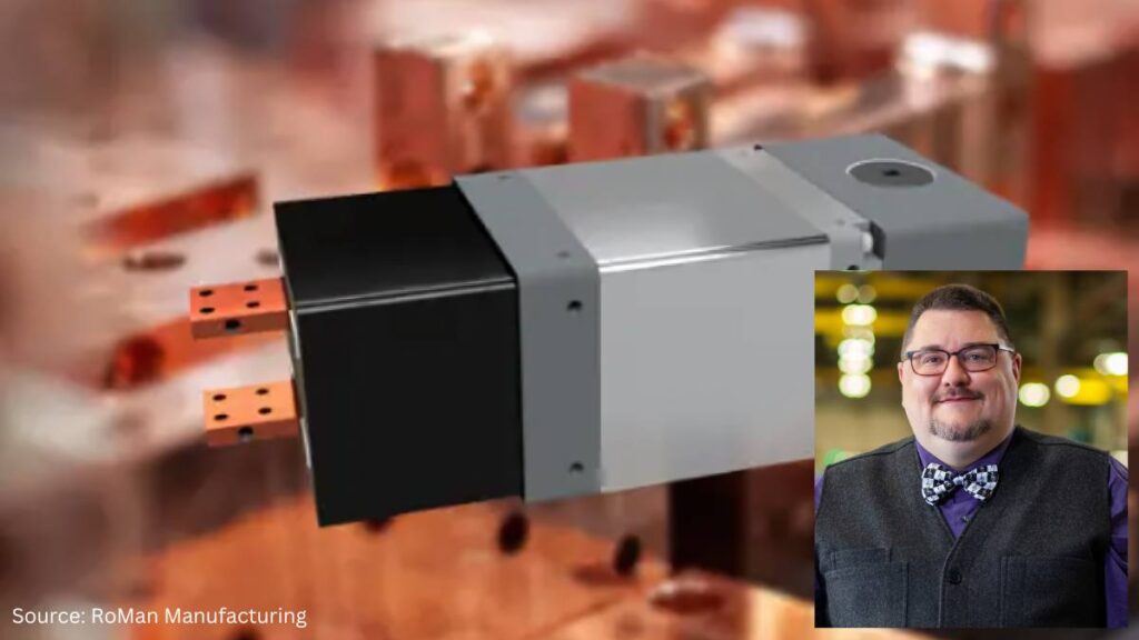
General Manager at Erie Steel, Ltd.
Sourced from the author

Michael Mouilleseaux is general manager at Erie Steel, Ltd. He has been at Erie Steel in Toledo, OH since 2006 with previous metallurgical experience at New Process Gear in Syracuse, NY, and as the director of Technology in Marketing at FPM Heat Treating LLC in Elk Grove, IL. Michael attended the stakeholder meetings at the May 2023 symposium hosted by the U.S. DOE’s Office of Energy Efficiency & Renewable Energy.

For more information: Contact Michael at mmouilleseaux@erie.com.  


US DOE Strategy: Why the Heat Treating Industry? Read More »

How To Tell If You Really Have an Abrasion Problem

Understanding abrasion can be the key to extending the life of your refractory lining. The following article provided by Plibrico Company examines abrasion resistance, its role in choosing a refractory solution, and what factors to take into consideration when assessing counter-measures.


Refractory material is designed to be very durable, withstand extreme service conditions and defy mechanical abuse in many different types of thermal-processing operations. However, severe conditions that cause abrasion in the form of high levels of mechanical scraping and airborne particulate matter can challenge refractories, shortening their service lives. 

Abrasion resistance is one of the most critical and possibly the most misunderstood considerations when choosing a refractory solution. A clear understanding of what abrasion is and, perhaps more importantly, what it is not can prevent needless repair costs and lead to significant savings. This is especially important when evaluating refractory designs for a new application or when considering upgrades for an existing one. 

What Abrasion Is 

Abrasion is the destructive process that causes a material to wear away through mechanical scraping or scratching. Anyone who has ever grated cheese or sanded wood has experienced the abrasion encountered in everyday life. As abrasion continues, thin layers of the abraded material are removed, leaving the object thinner and usually making its surface smoother. 

The same process can be observed in the refractory world. Refractory linings are abraded by high-velocity airborne particulate, cleaning tools and fuel/process materials that pass through the unit and come into contact with the lining. The telltale sign of abrasion is a refractory lining that has steadily become thinner while its surface has become smoother. The surface may even shine as if it had just been polished, which is not surprising when we consider that polishing is another common form of abrasion. 

Fig. 1. Abrasion damage to the refractory bottom of a choke ring of a thermal-oxidizer unit

What Abrasion is Not 

Abrasion is considered a type of mechanical abuse, but it is not the only type of mechanical abuse to which refractory linings are subjected. Equally common is impact: the sudden, forceful collision between the refractory lining and a moving object. Impact can come from a variety of sources. The moving object may be a cleaning tool, a piece of process material, a chunk of fuel or a dislodged mass of refractory or slag, depending on the application. Impact with such objects typically results in chips and cracks in the refractory lining. 

Refractory materials designed for abrasion resistance tend to have increased strength and hardness compared to those found in traditional refractories, and these abrasion-resistant materials may provide some resistance to impact. Abrasion-resistant properties can also lead to increased brittleness. This is because if the impact exceeds the strength of the material, chipping and cracking could potentially be worse than in traditional refractories. 

Compression and tension are also forms of mechanical abuse and can be caused by changes in the shape of the refractory lining as it is heated or cooled or by movements of the furnace shell itself – by intentional design or otherwise. Here again the increased strength and corresponding brittleness of the material could potentially result in a negative effect on the refractory lining. 

All types of mechanical abuse can cause thinning of the refractory lining, so it is important to conduct a detailed investigation into the destructive mechanism before drawing any conclusions. Refractory solutions designed to resist abrasion may not be helpful against damage caused by impact, compression or tension. 

Similarly, solutions designed to address other types of mechanical abuse may be ineffective against abrasion. For example, stainless steel needles are commonly incorporated into refractory linings to extend service life when impact resistance is required. The needles bridge cracks formed as a result of the impact, making it more difficult for these cracks to grow and connect. This helps the refractory lining hold together longer. The bridging provided by needles has no effect in an abrasion situation, however, since crack growth is not caused by the abrasion process. 

Meeting Abrasion-Resistance Demands 

Once abrasion is identified as the main mode of failure, there are several options to counter it. Selecting a refractory material based on a raw material hard enough to resist the abrasion is a common technique. For one material to abrade another it must be harder than the material being abraded. For instance, a diamond can be used to scratch glass, but glass cannot be used to scratch a diamond. 

It follows that refractory materials based on very hard raw materials, like silicon carbide, can be used to resist abrasion and extend the life of the lining. It should be remembered, however, that a refractory lining is made up of many different materials, not just the main constituent raw materials. Clay, cement, silica and other softer components will still be exposed and abraded even if abrasion of the main aggregate is stopped completely. 

Another option is to investigate the source of the abrasion and make adjustments to the process. Can a less-abrasive cleaning tool be used? Is there a way to limit the contact of the abrading process materials with the refractory lining? Is it possible to adjust the angle between the refractory lining and the incoming airborne particulate? 

A seemingly minor change in the process, with minimal cost and no downsides to the operation, can save in refractory replacement costs. When changes to the process are not an option, it is best to consider the abrasion resistance of the lining as a whole and select a specifically designed abrasion-resistant solution. A qualified, knowledgeable refractory solution expert with genuine experience will help you make the best decision for your specific application, taking into consideration the following: 

  • Speed of installation 
  • Service life 
  • All-in price 
Fig. 2. Airborne particle matter has contributed to the abrasion damage seen in the refractory of a thermal-oxidizer choke ring. Notice on the left side of the photo how the abrading of the refractory lining becomes worse.

Abrasion-Resistance Testing 

The most common measure of holistic abrasion resistance used to compare refractory solutions is the ASTM 704 test. This test exposes refractory lining materials to a stream of abrasive particulate that cause a portion of the sample to be abraded over time. By keeping sample size and shape constant – along with particle velocity, particle material and test duration – various refractory materials can be compared on an apples-to-apples basis. 

This testing can be performed by any qualified refractory testing lab and most reputable refractory manufacturers. Test results are recorded based on the volume of material lost from the sample during the test and are reported in cubic centimeters. Products with excellent abrasion resistance consistently test at 5 cc of loss or less, while elite materials can score less than 3 cc of loss. 

Products designed specifically for abrasion resistance will report ASTM 704 results on their material technical data sheets. It is important to remember that the abrasion-loss numbers reported on material technical data sheets are based on samples prepared in a lab under controlled conditions. Achieving these same properties in the field under real-world, job-site conditions would require a high-quality refractory installer partnered with a world-class refractory manufacturer. 

Fig. 3. Severe conditions lead to abrasion damage in the refractory lining of this dry-ash hopper. Notice the abrasion damage goes past the anchor line, leaving the bottom-left anchors exposed. 

Conclusion 

The thinning of a refractory lining due to abrasion is a source of frustration for many thermal-processing operations and is one of the most common modes of failure encountered in the refractory world. But, by taking the time to understand the failure mechanism and learn about the options available, you can realize significant savings by avoiding needless costs in the future. 

Learn more at www.plibrico.com

This article was initially published in Industrial Heating. All content here presented is original from the author.


How To Tell If You Really Have an Abrasion Problem Read More »

10 News chatter To Keep You Current

Heat Treat Today offers News Chatter, a feature highlighting representative moves, transactions, and kudos from around the industry. Enjoy these 10 news items.


Equipment

  • Premier Furnace Specialists received orders for nine pieces of heat treating equipment to be delivered to a range of manufacturing operations, all of which are currently in various stages of completion and testing or delivery and installation.
  • A manufacturer in the composites industry recently received shipment of a cabinet oven from Gruenberg, an industrial oven and sterilizer manufacturer. The furnace will be used for curing composite parts under a vacuum.
  • A second nitriding system was installed by Nitrex to increase capacity at Balexco, an aluminum extrusion company in Bahrain focusing on increasing production capacity.

Company & Personnel

Greg Miller
National Business Manager
Superheat
  • Cognizant, a professional services company that helps clients modernize technology, announced intent to acquire Belcan, a global supplier of digital engineering services for multiple industries, including aerospace, defense, and automotive.
  • Greg Miller has joined Superheat as national business development manager for the United Kingdom and Ireland. Greg will continue to work from his base in Lanarkshire, Scotland, bringing experience in manufacturing and preventative maintenance, with a foundation in induction heating.

Kudos

  • On July 2, 2024, David Lynch celebrated 40 years with Induction Tooling, Inc. This milestone was accomplished by his commitment to excellence and consistent hard-work and dedication.
  • Superheat, an on-site heat treatment service provider based in New Lenos, IL, recently received two Industrial Safety Training Council (ISTC) Safety Achievement Awards: one for achieving three consecutive years with zero recordable injuries and another for celebrating five years without an OSHA lost workday case. Bret Cadenhead, regional HSE manager at Superheat, represented the company at the awards event in Beaumont, Texas.
  • StandardAero celebrates 60 years of providing service to Pratt & Whitney Canada’s PT6A turboprop across four overhaul locations worldwide. In 1964, Dallas Airmotive (acquired by the company in 2021) became the first independent MRO provider to enter into a turboprop agreement with Pratt & Whitney Canada.
  • Centorr Vacuum Industries celebrates its 70th year in business in the vacuum furnace industry. The company was founded in Somerville, MA, as Vacuum Industries in 1954, and Centorr Furnace Company in 1962 in Suncook. NH. The two companies merged in 1989 in their current facilities in Nashua, NH.
  • Sławomir Woźniak, CEO of the SECO/WARWICK Group, celebrates five years in the position, managing all three brands: SECO/WARWICK, Retech, and SECO/VACUUM.
  • StandardAero’s engine overhaul center in San Antonio, TX, has completed correlation of its first test cell for the CFM International LEAP-1B turbofan engine, as part of its introduction of LEAP-1A and LEAP-1B maintenance, repair and overhaul (MRO) capabilities.

Find Heat Treating Products And Services When You Search On Heat Treat Buyers Guide.Com


10 News chatter To Keep You Current Read More »

Gas Equipment Provider’s Acquisition Increases Reach to Heat Treaters

A Georgia-based provider of natural gas measurement and control products and solutions has announced the acquisition of a distribution and service center for the natural gas industry, extending its capabilities for heat treating manufacturers.

Equipment Controls Company‘s acquisition of Tri-State Meter and Regulator Service, Inc. is expected to expand geographic reach and operational capabilities of both companies and merge field services, installation and testing, fabrication and design, and leak surveys.

“We’re excited to welcome the Tri-State team to Equipment Controls,” said Jeb Bell, president of Equipment Controls Company. “Tri-State has built its reputation on a foundation of exceptional service. Their motto, ‘The Service Matters,’ resonates with our values, and we’re eager to extend that level of service to our customers.”

“We look forward to our future with ECCO. Our shared vision and complementary strengths will enable us to deliver exceptional value to our customers and the natural gas industry as a whole,” said Paul Hayes, president of Tri-State Meter and Regulator Service, Inc.

ECCO will be keeping Tri-State’s brand, team, offices, products, and service offerings.

This press release is available in its original form here.


Find Heat Treating Products And Services When You Search On Heat Treat Buyers Guide.Com


Gas Equipment Provider’s Acquisition Increases Reach to Heat Treaters Read More »

Two Manufacturers Expand Operations With Nitriding Systems

Nitriding systems have expanded the operations at two global companies: a gear manufacturer for the automotive industry and a fuel injection systems manufacturer for the marine machinery industry. In both cases, the systems will be integrated into existing installations in order to increase production capacity.

NXHL-910512 nitriding furnace
Source: Nitrex

A Chinese gear manufacturer has added a fourth Nitrex nitriding furnace to its automated gear production, which includes the manufacturing of transmission gears, transfer case gears, synchronizers, and engine-gear rings for both local automotive OEMs and global markets.

“This expansion goes beyond capacity enhancement; it elevates the manufacturer’s in-house capabilities and tightens production controls,” said Tao Liu, sales manager at Nitrex China. “It allows the company to focus resources on driving innovation and sustainability across domestic and international vehicle markets, including the growing new energy vehicle (NEV) sector.”

A third Nitrex nitriding system has been installed at a manufacturer specializing in high-performance fuel injection systems for diesel engines in maritime vessels. The new NX-815 batch furnace with a 3300 lb. (1,500 kg) load capacity is specifically tailored for processing carbon steel and stainless steel parts and meets stringent requirements of the shipbuilding and industrial marine industries.

“As environmental regulations propel the shift towards alternative energy-powered ships, our advanced nitriding technologies play a crucial role. We are proud to support their expansion into stainless steel applications,” said Tao Liu.

Press releases are available in their original form here and here.


Find Heat Treating Products And Services When You Search On Heat Treat Buyers Guide.Com


Two Manufacturers Expand Operations With Nitriding Systems Read More »

Basic Definitions: Power Pathways in Vacuum Furnaces

Ever wish you had a map to follow when navigating your power source? In the following Technical Tuesday article, Brian Turner, sales applications engineer at RoMan Manufacturing, Inc., charts the route that power takes from the source to the load and back again in a vacuum furnace.


In a vacuum furnace, the journey from the load (the material being heat treated) to the incoming power involves a complex arrangement of components that deliver, control, and monitor electrical energy. Here’s a breakdown of the path from the source to the load and back to the source of incoming power of a vacuum furnace:

Load

The material — either an item or batch of items — that is undergoing heat treatment; can be metals, ceramics, or composites.

Heating Elements

Common materials for heating elements include graphite, molybdenum, or tungsten, depending on the temperature range and application.

Electrical Feedthrough

These are used to transmit electrical power or signals through the vacuum chamber wall. They often contain insulated conductors and connectors to ensure safe transmission without leaking air into the vacuum environment.

Conductors

The most common methods to connect power from a vacuum power source to the furnace’s feedthrough include air-cooled cables, water-cooled cables, and copper bus bar. Power efficiency can be improved when selecting the length, size, and area between conductors. This can be achieved by close coupling the power system to the electrical feedthroughs, reducing resistance and inductive reactance, and improving the power factor.

Machined Copper Bar
Source: RoMan Manufacturing, Inc.

Controlled Power Distribution Systems

The furnace market today generally relies on three primary types of control power distribution systems: VRT, SCR, and IGBT. Each of these technologies employs different methods to regulate the power input to the furnace, which in turn generates the required heat.

VRT (Variable Reactance Transformer)

  • The VRT controls AC voltage to the load, this is accomplished by a DC power controller that injects DC current into the reactor within the transformer.

SCR (Silicon Controlled Rectifier)

IGBT (Insulated-Gate Bipolar Transistor)

  • Balanced three-phase voltage is rectified through a bridge circuit to charge a capacitor in the DC bus. The IGBT network switches the DC bus at 1000Hz to control the AC output voltage to a Medium Frequency Direct Current (MFDC) power supply.
  • MFDC power supply transforms the AC voltage to a practical level and rectifies the secondary voltage (DC) to the heating circuit.
  • A line reactor on the incoming three-phase line mitigates harmonic content.

Control Systems

These systems manage the furnace’s operation, including driving the setpoint of the power system, temperature control, vacuum levels, and timing. They often consist of programmable logic controllers (PLCs), human-machine interfaces (HMIs), sensors, and other automation components.

Incoming Power

This is the origin of the furnace’s electrical energy, typically from a utility grid. It provides alternating current (AC), which is distributed and transformed within the furnace system to power all necessary components. In industrial settings, power companies usually charge for electricity based on several factors that reflect both the amount of electricity used and how it’s used. Some common charges/penalties are energy consumption (kWh), demand charges (kW), power factor penalties, and time-of-use (TOU) reactive power.

Conclusion

The careful arrangement of heating elements, electrical feedthroughs, conductors, and controlled power distribution systems allows for precise temperature control, ultimately impacting the quality of the processed material. Understanding the role of various control systems, such as VRT, SCR, IGBTs, and transformers is crucial for optimizing furnace performance and managing energy costs

About the Author:

Brian Turner
Sales Applications Engineer
RoMan Manufacturing, Inc.
Source: RoMan Manufacturing, Inc.

Brian K. Turner has been with RoMan Manufacturing, Inc., for more than 12 years. Most of that time has been spent managing the R&D Lab. In recent years, he has taken on the role as applications engineer, working with customers and their applications.

For more information: Contact Brian at bturner@romanmfg.com.


Find Heat Treating Products And Services When You Search On Heat Treat Buyers Guide.Com


Basic Definitions: Power Pathways in Vacuum Furnaces Read More »

groundbreaking ceremony for Toyota Material Handling, banner in background, 4 men with shovels in the fg

Toyota Material Handling Expands, Adds 85 Manufacturing Jobs

Toyota Material Handling is investing nearly $100M for a new 295,000-square-foot facility at its Columbus, Indiana, headquarters, adding 85 manufacturing jobs by June 2026. The project will house Toyota’s manufacturing processes, which include the production of electric forklifts and material handling products.

“We are excited about this significant strategic expansion to our Columbus campus,” said Tony Miller, senior vice president of Engineering, Operations & Strategic Planning at Toyota Material Handling, at a recent groundbreaking ceremony. “Electric products are more popular than ever, and we are committed to doing whatever it takes to keep up with increased demand.”

“Electric forklifts make up 65% of the North American market and this trend towards electrification in the material handling industry will continue to grow,” said Brett Wood, president & CEO of Toyota Material Handling North America and senior executive officer for Toyota Industries Corporation (TICO). “This investment is one of the largest in our history and signifies TICO’s commitment to the North American market, the state of Indiana, the city of Columbus, and most importantly, our dealers and our customers.”

Photo Pictured L to R: Brett Wood, Toyota Material Handling North America President & CEO; Eric Holcomb, Governor of Indiana; Bill Finerty, Toyota Material Handling President & CEO; Tony Miller, Toyota Material Handling Senior Vice President of Engineering, Operations & Strategic Planning   


The press release is available in its original form here.


Find Heat Treating Products And Services When You Search On Heat Treat Buyers Guide.Com

Toyota Material Handling Expands, Adds 85 Manufacturing Jobs Read More »

This Week in Heat Treat Social Media

Welcome to Heat Treat Today’s This Week in Heat Treat Social Media. We’re looking at hot summer events, hot summertime activities, and hot heat treat industry events coming soon to a social media page near you. Check out these posts, podcasts, and videos for a roundup in Heat Treat Social Media.

As you know, there is so much content available on the web that it’s next to impossible to sift through all of the articles and posts that flood our inboxes and notifications on a daily basis. So, Heat Treat Today is here to bring you the latest in compelling, inspiring, and entertaining heat treat news from the different social media venues that you’ve just got to see and read! If you have content that everyone has to see, please send the link to editor@heattreattoday.com.


1. Heat Treating Skateboards > Hot Moves

This space is usually reserved for something rich and technical, but it’s summertime in the northern hemisphere and heat treating is just as essential for the proper working of items affiliated with leisure and outdoor activities as the products that make the world go round (e.g., automotive, aerospace, etc.). “Skateboarding is not just a sport; it’s an art form, a mode of transport, and a way of life for many. But did you know that the metal trucks on a skateboard—those T-shaped pieces that mount the wheels to the deck—are a product of meticulous heat treatment?” (from Bodycote on LinkedIn, November, 2023)

Check out this recent post from Bodycote laying out how critical it is to safety and experience for skateboard trucks to be heat treated with the same level of skill that it takes to execute an ollie or a shuvit.

2. It’s a Beautiful Day in the Heat Treat Neighborhood

What’s everyone been up to on the social channels?

Summer Engineering Institute reshaping the Future of Heat Treating

Future Leaders: Report to the Dome!

Take Us Out to the Old Ballgame!

It may Be Summer but It’s Never Too Early to Think About the Fall

‘Tis also the season for Registration for 2024’s industry events and social media provides an excellent platform for getting the word out. Here are some of the events taking place just in September — don’t delay! Registration is still open for all of these!

Marking Milestones

3. Learn with Us

Sometimes, it’s the small things on social media that grab your attention or give you the “ah ha!” moment. And sometimes things affecting the industry in other places cause us to go “hmm.” Do any of these short posts make you say “eureka”?

Queueing and Sequencing (and more!)

Quiz Time

4. Open Your Ears: The Podcast Corner

You can’t read everything, we get it. Heat Treat Today is here to recommend two informative podcasts to enjoy on your daily commute!

Tune in to Listen to Heat Treat Radio #110! Isolated Heat, the Future of Vacuum Furnaces

smiling bearded man on blue background, HTR 110 logo, isolated heat text

Sharpen your hearing: Heat Treating Knives on the TTT Podcast

5. Junk Food and a Logo Extravaganza

Click through to see what Kowalski Heat Treating thinks about junk food and how that thinking gets them counting logos.

Have a great weekend!


Find Heat Treating Products and Services When You Search on Heat Treat Buyers Guide.com

This Week in Heat Treat Social Media Read More »

5 digital screens and devices, one with a hand and finger touching a screen; background faded silver/gray design

Thermal Loop Solutions, Part 2: A Path to a Sustainable Future in Heat Treatment


Sustainability

Heat treatment thermal loop solutions provide several sustainability benefits, including reduced energy consumption and waste. The power controller regulates the power output to minimize energy waste, and the possible integration with renewable energy sources and circular economy principles provides a complete power solution that spans from element design to recycling and renewables. The thermal loop solutions, in combination with insulation design and materials, provide energy-efficient solutions that contribute to sustainability and reduce the environmental impact of heat treatment processes.

When discussing these systems in the context of greenhouse gas emissions and their environmental impact, it is essential to consider Scopes 1, 2, and 3, as well as the less common Scope 4:

  • Scope 1 (Direct Emissions): Heat treatment processes often involve the combustion of fossil fuels like natural gas, propane, or oil to generate heat. These direct emissions are attributed to the equipment used in the heat treatment process, such as furnaces and ovens. Efforts to reduce Scope 1 emissions include upgrading to more efficient equipment or adopting alternative heating technologies, like induction or electric heating systems.
  • Scope 2 (Indirect Emissions from Energy): In heat treatment processes and thermal loop systems, electricity is often used to power various components, such as pumps, fans, and control systems. The emissions associated with generating this electricity are considered Scope 2 emissions. To reduce Scope 2 emissions, companies can improve energy efficiency, invest in renewable energy sources, or purchase green energy from their utility provider.
  • Scope 3 (Other Indirect Emissions): These emissions are associated with activities throughout the value chain of heat treatment applications and thermal loop systems, such as the manufacturing and transporting of raw materials, equipment, and waste management. Companies can work to reduce Scope 3 emissions by collaborating with suppliers to improve the environmental performance of their products and services, optimizing transportation and logistics, and implementing waste reduction strategies.
  • Scope 4 (Avoided Emissions): In heat treatment applications and thermal loop systems, avoided emissions may come from implementing energy-efficient technologies, waste heat recovery systems, or other innovative solutions that reduce overall energy consumption and associated emissions. By quantifying these avoided emissions, companies can showcase the positive impact of their sustainability efforts on reducing their carbon footprint. Avoided emissions can also be highlighted when subcontracting heat treatment requirements to a more energy-efficient source rather than running an in-house operation. In this approach, the heat treatment process is outsourced to an external, specialized heat treatment service provider, especially if the in-house equipment is due to be lightly utilized. These service providers operate independent heat treatment facilities and offer services to multiple clients across various industries and generally run 24/7 with high utilization.

At the component level, energy savings can be realized using current technology. Advanced SCRs provide predictive load management functions and hybrid firing algorithms and contribute to sustainability by optimizing the energy usage of heat treatment processes. These SCRs offer real-time monitoring and control of energy consumption, while predictive load management systems use specific algorithms to manage peak power loads and adjust to optimize for local conditions (load shedding or load sharing). Hybrid firing systems use a combination of firing methods to control power factors and reduce the negative impact on the electrical infrastructure.

Heater design is also essential. Switching time impacts heater life with fast, modern switching modes (hybrid firing) significantly extending heater life compared to slower switching from conventional mechanical contactors.

Systems can be rapidly tested, simulated, and modeled through computational engineering. Several thermal loop systems today have improved temperature uniformity due to these methods.

Adaptive thermal system (ATS) solutions are the next frontier of thermal loop solutions. Rather than selecting the best-of-breed components — sometimes with overlapping functionality and kitting a complete solution — ATS provides a merged design between heater and control systems. ATS is already in place in several semiconductor applications, and this type of technology is looking to scale into heat treatment applications shortly.

graphic of 2 circular images (predominantly green), red arrow between; text: Watlow Introduces Adaptive Thermal Systems
Figure 2. Watlow Adaptive Thermal Systems ATSTM
Source: Watlow

Challenges and Limitations

The initial investment in heat treatment thermal loop solutions can sometimes be higher than in traditional methods. However, this investment often leads to a significantly lower total cost of ownership and improved return on investment due to the thermal loop solutions’ increased efficiency, improved quality control, and extended life.

Ensuring regulatory compliance is complex and time-consuming, requiring organizations to have the right people, processes, and equipment.

Future Trends

As Industry 4.0 and digital transformation continue to gain momentum and Industry 5.0 practices are implemented, heat treatment thermal loop solutions will become increasingly important. Integrating digital technology and machine learning algorithms will provide even greater control, traceability, and transparency, enabling organizations to make informed decisions based on real-time data and predictive analytics. In addition, as new materials and manufacturing processes are developed, adaptive and flexible heat treatment thermal loop solutions will need to evolve to meet these challenges and provide the necessary level of control and efficiency for these new applications.

Conclusion

Heat treatment thermal loop solutions provide several benefits over traditional heat treatment methods, including improved temperature control, increased efficiency, and improved sustainability outcomes. The integration with Industry 4.0 and data management systems, as well as the use of FMEA and OEE metrics, further help enhance the performance of heat treatment processes. As Industry 4.0 digital transformation and Industry 5.0 practices continue to evolve, heat treatment thermal loop solutions will play an increasingly important role in the future of heat treatment.

About the Authors:

Peter Sherwin
Global Business Development Manager of Heat Treatment
Watlow
Thomas Ruecker
Senior Business Development Manager
of Heat Treatment
Eurotherm, a Watlow company

Peter Sherwin, global business development manager of Heat Treatment at Watlow, is passionate about offering best-in-class solutions to the heat treatment industry. He is a chartered engineer and a recognized expert in heat treatment control and data solutions.

Thomas Ruecker is the business development manager of Heat Treatment at Eurotherm Germany, a Watlow company. His expertise includes concept development for the automation of heat treatment plants, with a focus on aerospace and automotive industry according to existing regulations (AMS2750, CQI-9).

For more information: Contact peter.sherwin@watlow.com or thomas.ruecker@watlow.com.

This article content is used with permission by Heat Treat Today’s media partner heat processing, which published this article in 2023.


Find Heat Treating Products And Services When You Search On Heat Treat Buyers Guide.Com


Thermal Loop Solutions, Part 2: A Path to a Sustainable Future in Heat Treatment Read More »

Digital Technology Powers Green Heat Treat

“Communication is key.” As heat treating equipment and processes evolve, it becomes critical that the accompanying control systems also develop to maintain “communication.” In this Technical Tuesday installment, guest columnist Stanley Rutkowski III, senior applications engineer at RoMan Manufacturing, Inc., discusses how digital control system communications have improved to increase energy efficiency for manufacturers with in-house heat treat operations.

This informative piece was first released in Heat Treat Today’s May 2024 Sustainability Heat Treat print edition.


Industrial furnace applications that rely on resistive heating will consume large amounts of electrical energy when processing their loads. Utilizing digital controls technologies to maximize this type of heating allows for a cleaner-and thus greener-approach to energy demands.

Typically, heat treat processes have a long duration (hours to days in length), and each load can have its own unique recipe in the amount of power required. With unique recipes, there tends to be a ramp-up phase (getting the vessel to temperature), followed by a soak phase (which demands more control over the power system), and then a cool-down phase (an even more controlled state). As the power is controlled through the furnace system, disturbances occur with different technologies. This starts with “tube technology,” then variable reactance transformer (VRT) technology, then silicon controlled rectifier (SCR) technology, and finally IGBT (insulated-gate bipolar transistor) technology. As these technologies have evolved, their ability to communicate information digitally has allowed for less disturbance in the power system and allowing both a less expensive energy bill and a cleaner energy usage for the process.

Definitions

Electrical Power

Power losses in an electrical system are defined by five aspects (Figure 1):

  1. Resistance (R): a function of the material cross section and the length of an electrical conductor.
  2. Reactance (XL): a function of the area in a circuit and is a vector 90 degrees offset from resistance.
  3. Capacitance (XC): a vector 180 degrees offset from reactance. In inductive circuits, capacitance can be added for power factor correction.
  4. Impedance (Z): the vector sum of resistance, reactance, and capacitance.
  5. Power Factor [cos(F)]: the ratio of resistance to impedance. In industrial applications, displacement power factor (DPF), the offset of the current to voltage waveforms, is used in the billing of electrical power.

There are five unique aspects that define electrical power usage (Figure 2):

  1. Real power (kW): the amount of power that is generated.
  2. Reactive power (kVAR): the amount of power that is wasted.
  3. Total power (kVA): the rate at which power is consumed. This is also referred to as apparent power.
  4. Power factor (cos(F)): the ratio of real power to total power. In industrial applications, the displacement power factor (DPF) is the offset of the current to voltage waveforms and is used to bill for electrical power.
  5. Peak demand: the capacity required when the power grid experiences the highest power demand in a specified period of time.

3 Most Popular Types of Control Systems

For the most part, today’s furnace manufacturers use three main types of control systems: VRT, SCR, and IGBT. Each operates with slightly different methods to control how power goes into the heat treat furnace and creates heat.

VRT Control System

One traditional resistance heating setup uses a VRT control system that incorporates a saturable reactor, which controls the power applied to the transformer in the system (Figure 3). The control transformer on the output side of the transformer feeds back to the reactor to set the limit on the input power to the transformer.

Figure 3. VRT Control and Transformer Schematic (CT=control transformer); Source: RoMan Manufacturing, Inc.

SCR Control System

Figure 4. SCR Control and Transformer Schematic; Source: RoMan Manufacturing, Inc.

Another traditional resistance heating setup uses an SCR control system that includes dual thyristors (gated diodes) to control the amount of power applied to the primary of a transformer.

The SCR control delays the start of the waveform, and the control point is reset when the waveform crosses the zero line.

Figure 5. Comparison of Sine Waves; Source: RoMan Manufacturing, Inc.

IGBT Control System

Finally, an IGBT control system uses a diode bridge, capacitor, and switching transistors to control the amount of power applied to the primary (i.e., main power input of a transformer). The input frequency to the transformer is controlled by the switching transistors. Since the IGBT control system utilizes all three phases of the power system, the IGBT control can be set to a particular phase for the zero cross (for phase orientation in the application, synchronous mode) or left floating (non-synchronous mode), as is demonstrated in Figure 6. The input voltage to the transformer is increased by the operation of the IGBT control. As such, potential energy savings may be had with these types of controls as compared to tradition controls (such as on-off contractors, time proportioning controls, or other types of current proportioning control systems).

Figure 6. IGBT Control and Transformer Schematic; Source: RoMan Manufacturing, Inc.

Synchronization with the IGBT can be to the incoming lines (A, B, or C phase) and can be offset from each of the phases. The ability to offset from a phase allows for traditional arrangements (Single Phase, Scott-T, Delta and Wye) as well as unique offsets allowing for additional vector heating in the application with AC outputs. The unique arrangements beyond the traditional systems could allow for more uniform heating of the part and less energy being consumed during the process.

Advantages of Utilizing Communications

As technology for controlling heating systems has evolved, and with an emphasis on clean energy sources, the ability to communicate with the control system has increased as well. This communication allows for more precise control of the run for the load, improved power usage (better power factors and less peak power usage as well as less total power usage), and inputs into a preventive maintenance program.

Table A. Analog vs. Digital IGBT Systems

With an IGBT system, both analogue and digital control communications are available today. See Table A for a comparison on how each control option works.

In addition to the EIP defined pieces, there is the ability to access the FPGA system for graphical outputs that can be downloaded into another system in your process for storage, comparisons, or general record keeping for a part run. The FPGA is an internal processor in the control that allows for more data, charting, and diagnostics to be captured and used by the system for both energy consumption and possible preventative maintenance purposes.

Why does this matter? Let’s turn to some possible ways of using the data generated from digital controls systems:

  1. Evaluate average, minimum, and maximum DC bus voltages to plan for the best time and day to run heat treat jobs. For high power draw jobs, planning ahead can minimize power costs; similarly, knowing power trends can be helpful to plan jobs requiring sensitive control of the heating.
  2. Evaluate transformer output voltage to allow the system to detect any shorts in the process. If the controller output and transformer output diverge from the known turns ratio, a change has occurred in the system. This could be corroborated if controller on time and output power do not trend.
  3. Track furnace run records with EIP communications and FPGA data. This will be most helpful in processing lots of data, as is the case for Milspec records.
  4. Evaluate changes in power factor to monitor any loose cables, and so avoid reactive power losses.
  5. Evaluate the current versus the voltage to monitor the resistance of the system. If there is an increase in the resistance, you could project the trends in wear of the heating elements, therefore predicting future required maintenance.
  6. Evaluate the critical control temperatures of the system to know if it is being run close to, or above, its ratings or if there is a disturbance in the cooling systems.
  7. Use knowledge of power usages and power stability to update recipes for load runs so they use less power over the total run; this allows for a less costly power-savings solution. With less power usage, more output of the total facility can be had as each station contributes less to energy consumption

Even more benefits can be realized when users and builders of furnace systems and component manufacturers collaborate in the design of the total system. Such dialogues lead to the creation of more interactive and intuitive solutions that minimize power consumption, minimize downtime, and maximize outputs. These practical benefits are the foundation of a greener system.

About the Author:

Stanley F. Rutkowski III
Senior Applications Engineer
RoMan Manufacturing, Inc.

Stanley F. Rutkowski III is the senior applications engineer at RoMan Manufacturing, Inc., working on electrical energy savings in resistance heating applications. Stanley has worked at the company for 33 years with experience in welding, glass and furnace industries from R&D, design, and application standpoints. For more than 15 years, his focus has been on energy savings applications in industrial heating applications.

For more information: Contact Stanley at srutkowski@romanmfg.com.


Find Heat Treating Products and Services When You Search on Heat Treat Buyers Guide.com

Digital Technology Powers Green Heat Treat Read More »

Skip to content